Note: Descriptions are shown in the official language in which they were submitted.
CA 02664388 2009-03-25
WO 2008/037049
PCT/CA2006/001570
MICRO-DIFFRACTIVE SURVEILLANCE ILLUMINATOR
SPECIFICATION
FIELD OF THE INVENTION
This invention relates to the field of infra-red illumination for low-light
video surveillance, and
to the application of refractor technology, in particular micro-diffractive
engineered material. It
also relates to wide-angle video surveillance for such as multi-lane traffic
licence plate reading.
BACKGROUND
Due to the inverse square law of illumination, the intensity of light falling
on a target area
decreases in proportion with the square of the distance. When using a camera
and lens
arrangement to view a typical surveillance scene a certain proportion of the
image contains the
foreground and a certain amount the background. The amount of light required
or optimal to
illuminate the foreground of a target area is usually much lower than that
required to illuminate
the background of a target area. Additionally target areas in surveillance are
typically more
extended horizontally than vertically, because most target areas are based on
a horizontal ground
1
CA 02664388 2009-03-25
WO 2008/037049
PCT/CA2006/001570
area, across which peoples or vehicles travel.
Most illumination systems produce a circularly diverging beam which when used
with a camera,
which requires the installer to point the peak of the beam at the farthest
target point. For a fixed
target distance there is an optimum beam profile in the vertical orientation.
When viewing at the
same distance with a wider and wider view and matching the circular
illumination the illuminator
moves further away from the optimum in the vertical orientation and wastes
more light.
Moreover, as the peak of the light source is pointed above the line of the
target, a large
proportion of the light is above the target area and is not utilized.
There are many systems which use infrared illumination for low light
photography or video
photography. There are also many systems which use LEDs for photographic or
video
illumination. Some of these systems utilize refractive or reflective elements
to diffuse or focus
illumination.
Illuminators using LEDs with refractive or reflective elements to enhance
illumination are varied
and include a number of different types of refractors which channel light from
the LEDs so as to
alter the distribution of illumination on the target and/or to make
illumination more efficient by
conserving light.
There are also a number of devices in which lights are fitted with micro-
prisms or similar
constructions to refract light onto a target. Some of these devices are used
in projectors or similar
2
CA 02664388 2009-03-25
WO 2008/037049 PCT/CA2006/001570
systems or in media effects systems for backlighting.
Several necessities prior to this invention have combined to limit the
technology of low light
illumination for wide-angle nighttime surveillance video photography,
particularly for license
plate capture and reading, when several vehicles' headlights may be pointed
toward a
surveillance camera. There is a need to pulse the surveillance illumination to
conserve energy.
There is a need to synchronize a surveillance camera to the pulsed
illumination returning to the
camera after having fallen on a moving target. There is a need to illuminate a
wide area in the
case of vehicles traveling across lanes or where multiple lanes of vehicles
are targeted. There is a
need for wide-angle effective illumination matching wide-angle high pixel
density cameras in
order to capture tiny fast-moving license plates out of a large wide-angle
scene such as a
multi-lane freeway.
SUMMARY OF THE INVENTION
The present invention provides a surveillance illuminator system in which a
micro-diffractive
material comprising is placed in front of a light-emitting manifold such as a
bank of infra-red
LEDs to alter the shape of illumination on a target area for wide-angle
surveillance under low
light conditions. The illumination field produced has an elliptical Gaussian
shape. The
illuminator is designed to be used in connection with a wide-angle
surveillance camera having an
aspect ratio sensitivity matching the light pattern produced by the
illuminator. This novel
3
CA 02664388 2009-03-25
WO 2008/037049 PCT/CA2006/001570
combination represents a breakthrough for the quality of background
illumination for
surveillance and nighttime video and photography as it results in wide
illumination patterns
without moving away from the optimum vertical profile.
This invention results in the ability to produce an asymmetrical illumination
pattern enabling
increased sensitivity for wide area photographic or video coverage, such as
wide-angle views of
multi-lane traffic; optimization of the vertical spread of illumination under
the cosecant squared
distribution for more efficient background illumination; in the reduction in
the number of LEDs
which would normally be used for a new angle configuration; and in reduced
light pollution
including non-visible light pollution.
This invention is useful in an intelligently secured transportation system, in
which surveillance of
a multi-lane roadway is performed with a mega-pixel camera having a wide-angle
aspect, in
conjunction with a mega-wide monitor. The surveillance illuminator system of
the present
invention provides less light where it is unneeded in the top or bottom of the
field of view and
more light in an extended central area. The surveillance illuminator system
therefore conserves
power. It enables the available power and heat dissipation characteristics of
the illuminator
system's light source to effectively illuminate the wide-angle horizontal
problem area. Less light
overall is thereby needed to achieve ultra-high quality image capture of small
target sub-sections
of the scene because the light is more efficiently focused on the target sub-
sections by the
micro-diffractive material.
4
CA 02664388 2009-03-25
WO 2008/037049 PCT/CA2006/001570
The invention provides a surveillance illuminator system in which a micro-
diffractive material
that is "mono-directional" in that is statistically more directional for light
in a first plane of
output than in another output plane, such as in a horizontal output plane than
in a vertical output
plane, is mounted in front of a light-emitting manifold comprising a plurality
of light sources,
such as a planar array of light-emitting diodes (LEDs) array emitting light
having a wavelength of
approximately 850 nanometers, in the infrared range from 700 to 1000
nanometers. In an
especially efficient embodiment, the system has a surveillance camera having
an aspect ratio
sensitivity substantially matching a light pattern projected by the mono-
directional
micro-diffractive material mounted in front of the light-emitting manifold.
This invention may employ a double layer of the micro-diffractive material
which combines
horizontal and vertical sets of material to produce different asymmetrical
combinations from a
smaller subset of lens shapes and in some combinations may extend the maximum
angle of
diffraction.
This invention can also use different micro-diffractive material above the mid-
line of the
illuminator than below may allow an asymmetrical vertical beam profile which
enables more
efficient use of the light resulting in increased illumination distances.
The invention thus provides significantly increased usable distance from prior
illuminators, for
example 110 meters compared to 54 meters for a light source comprising LED's
having a 60
degree angle of light dispersion before micro-diffraction. The foreground /
background ratio of
CA 02664388 2009-03-25
WO 2008/037049 PCT/CA2006/001570
illumination is also much more even with the present invention, making for a
significantly better
image because the camera needn't try to adjust the exposure to the foreground;
it is able to
make better use of the light on the target scene.
BRIEF DESCRIPTION OF THE DRAWINGS
Figure IA is a top down view of a section of the illuminator showing light
rays from the light
emitting manifold traveling through the mono-directional micro-diffractive
material and being
diffracted horizontally.
Figure 1B is a side view of the section of the illuminator showing light rays
from the light
emitting manifold traveling through the mono-directional micro-diffractive
material with
negligible vertical diffraction.
Figure 2A is a horizontal cross-sectional view of the mono-directional micro-
diffractive material.
Figure 2B is a vertical cross-sectional view of the mono-directional micro-
diffractive material.
Figure 3 shows the structure of the micro-diffractive material under high
magnification
Figure 4 is a perspective view of the rectangular LED array showing the heat
sink and the
6
CA 02664388 2009-03-25
WO 2008/037049 PCT/CA2006/001570
constant current power source.
Figure 5 is a perspective view of the mono-directional micro-diffractive
material overlaid on the
rectangular LED array.
Figure 6 is a view of the target image illuminated by a conventional infra-red
illuminator. It
illustrates how the power density for a circular beam pattern reduces as it
gets wider to take in the
extent of an asymmetrical target.
Figure 7 is a view of the target image illuminated by the mono-directional
micro-diffractive
material rectangular LED array illuminator. It shows that using an elliptical
or asymmetrical
beam pattern there is practically no wasted light.
Figure 8 shows another embodiment of this invention using different material
above the mid line
of the illuminator than below to allow an asymmetrical vertical beam profile.
Figure 9A plots the distribution function of light emitted by the illuminator
in terms of quantity
of light and horizontal divergence angle. The full width-at half maximum
(FWHM) of the
function is shown.
Figure 9B plots the distribution of light emitted by the illuminator in terms
of quantity of light
and vertical divergence angle. The full width-at half maximum (FWHM) of the
function is
7
CA 02664388 2009-03-25
WO 2008/037049
PCT/CA2006/001570
shown.
Figure 10A shows a vehicle and its license plate illuminated by a conventional
illuminator with a
circular beam.
Figure 10B shows two vehicles and their license plate illuminated with an
illumination beam of
similar area using the micro-diffractive light emitting manifold illuminator.
Figure 11A shows a four lane roadway scene illuminated by the micro-
diffractive light emitting
manifold illuminator and the same scene captured by a wide-angle CCTV camera
and displayed
on a wide-angle monitor.
Figure 11B shows a four lane roadway scene illuminated by the micro-
diffractive light emitting
manifold illuminator and captured two lanes at a time by four CCTV video
cameras. The
integrated image is displayed on a wide-angle monitor.
Figure 12A is a top down view of a section of the illuminator showing light
rays from the light
emitting manifold traveling through a spherical lens and narrowing before
passing through the
mono-directional micro-diffractive material and being diffracted horizontally.
Figure 12B is a side view of the section of the illuminator showing light rays
from the light
emitting manifold traveling through a spherical lens and narrowing before
passing through the
8
CA 02664388 2009-03-25
WO 2008/037049 PCT/CA2006/001570
mono-directional micro-diffractive material with negligible vertical
diffraction.
DETAILED DESCRIPTION
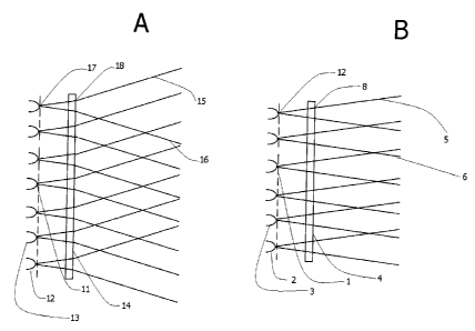
Referring to Figure 1A, the light emitting manifold 11 seen in a top down
view, which contains a
number of near point-source lights such as 12 and 13, sends rays of light such
as 17 through a
mono-directional micro-diffractive material 14 which causes the rays of light
to diverge
horizontally as at point 18, so that the outgoing light rays 15 and 16 travel
out from the
illuminator at greater angles.
Referring to Figure 1B, the light emitting manifold 1 is seen in a side view,
with point-source
light 12 shown at the top, and point-source lights 2 & 3 which are below the
visible plane of
figure 1A. Light from the manifold 1 passes through the micro-diffractive
material 4, but the
mono-directional nature of the micro-diffractive material enables the light to
pass through
without significant vertical divergence as a point 8. The outgoing rays of
light such as 5 and 6
continue close to their initial trajectories.
Referring to Figure 2A, a beam of light from an LED 20 characterized by light
rays 25 & 26
passes through a micro-diffractive lens 21 on a magnified horizontal cross-
section of
micro-diffractive sheet 22. The rays 25 & 26 are diffracted to greater
incidence angles at points
9
CA 02664388 2009-03-25
WO 2008/037049 PCT/CA2006/001570
23 and 24 on the micro-diffractive lens 21. The new trajectory of the rays is
shown by 27 & 28
respectively as contrasted with the original path represented by dotted lines.
Referring to Figure 2B, a beam of light from an LED 30 characterized by light
rays 34 & 35
passes through a magnified vertical cross-section of the micro-diffractive
sheet 32. The new
trajectory of rays 34 & 35 is shown by 36 & 37 respectively to be very nearly
identical to the
original trajectory. This is due to the extreme flatness of the lens structure
of the
micro-diffractive sheet in the vertical dimension. At this level of
magnification, no curvature can
be seen to define a lens and no inflection is visible at points 31 & 33.
Referring to Figure 3, a microscopic segment of the micro-diffractive material
is shown, at very
high magnification with nanoscopic refractive structures as at 122, 123, 124,
& 125 that appear
like waves. The length and relative flatness of the wave crests allows for
less diffraction in the
vertical plane than in the horizontal plane. The aligned nanoscopic structures
cause the
micro-diffractive sheet statistically to tend to refract light at a different
angle in one plane such as
a horizontal plane than in another plane perpendicular to the first, such as a
vertical plane.
Referring to Figure 4, the rectangular LED array 41, is mounted on the
illumination housing 43,
within a frame 42. The housing 43 is equipped with a heat sink 45, and a
constant current power
source 46. It can be mounted with a bracket 44. The front window 47 for the
light emitting
manifold has optical filter properties that pass substantially all infrared
light energy while
blocking light at shorter wavelengths;
CA 02664388 2009-03-25
WO 2008/037049 PCT/CA2006/001570
Referring to Figure 5, a sheet composed of micro-diffractive material 50 is
shown overlaying a
small section of the LED array 51. LEDs such as 52 & 54 appear slightly
blurred beneath the
sheet of micro-diffractive material 50. The LED housing 53 contains the LED
array 51.
Referring to Figure 6, the power density for a circular beam pattern 71
reduces as it gets wider to
take in the extent of the asymmetrical targets 72 (house) and 73 (roof). The
total power is divided
over the area of the larger circle 70. Much of the power is then wasted above
and below the
target.
Referring to Figure 7, in using an elliptical or asymmetrical beam pattern 81
there is practically
no wasted light in the area where a circular beam 80 extends above and below
the elliptical beam
81 while the beam illuminates wide targets such as roof 82 and house 83. This
is very efficient
use of the light available and thus can be used to increase the obtainable
imaging distance or
reduce the number of multiple illuminators that may be required for a
particular application or
reduce the size of illuminator required and decrease the electrical power
required for a particular
application.
Referring to Figure 8, using different material above the mid line 91 of the
illuminator than
below allows an asymmetrical vertical beam profile 93. More efficient use of
the light can be
achieved resulting in increased illumination distances. A conventional
illuminator would have a
beam profile more like 92 with a much greater extent along the vertical axis
90.
11
CA 02664388 2009-03-25
WO 2008/037049
PCT/CA2006/001570
Referring to Figure 9A, the distribution of light emitted by the illuminator
is plotted as a
bell-shaped curve. On the vertical axis the quantity of light is shown against
the horizontal
divergence angle of the light from the illuminator on the horizontal axis. The
full width-at half
maximum (FWHM) of the function is shown between -67.5 and +67.5 indicating a
significant
horizontal divergence of 130 degrees of the light from the illuminator, the
top of the curve being
zero angle toward the center of the field of illumination.
Referring to Figure 9B, the distribution of light emitted by the illuminator
is plotted as a
bell-shaped curve. On the vertical axis the quantity of light is shown against
the vertical
divergence angle of the light from the illuminator on the horizontal axis. The
full width-at half
maximum (FWHM) of the function is shown between 6 and 12 degrees, indicating a
very low
vertical divergence of the light from the illuminator.
Referring to Figure 10A, a target license plate 62 and reflectors 64 and 66
are illuminated by a
conventional infrared beam 60. The images appear blurred due to insufficient
concentration of
light. This is a problem which arises because with a conventional illuminator,
much light is
wasted illuminating the background.
Referring to Figure 10B, two lanes separated by dotted line 68 are illuminated
by the wider beam
61 of the micro-diffractive surveillance illuminator. In the leftmost lane the
target license plate
63 and reflectors 65 and 67 are all clearly illuminated by the concentrated
elliptical illumination
beam 61 produced by the light emitting manifold micro-diffractive illuminator.
Due to the
12
CA 02664388 2009-03-25
WO 2008/037049 PCT/CA2006/001570
efficiency of the illumination beam a second target license plate 69 in the
rightmost lane is also
illuminated despite the fact that the total area and total power usage of the
illumination beam in
Figure 10B is comparable to that in Figure 10A. The micro-diffractive material
is formed and
arranged such that it projects an elliptical Gaussian distribution of
refracted light, having a major
axis of diffraction in the horizontal plane and a horizontal divergence in a
range greater than
double the angular divergence of the array of LEDs and a vertical divergence
substantially
unaffected by the micro-diffractive material. In the license plate application
¨ the
mono-directional micro diffractive material will allow multiple lanes to be
covered with the same
or less illumination compared to existing surveillance illuminator and camera
systems by
enabling the camera to make much better use of the illumination on scene.
Referring to Figure 11A, the light emitting manifold micro-diffractive
illuminator 201 is shown
illuminating a scene 211 consisting of a four-lane highway 213. The image of
the highway is
captured by a wide-angle CCTV camera 202, which transmits the image to a wide-
angle video
monitor 203 where it is displayed as 215. The arrows (such as 200) which point
outward from the
illuminator indicate outgoing light. The arrows (such as 199) which point
inward to the camera
indicate the incoming light from the illuminated scene 211.
Referring to Figure 11B, the light emitting manifold micro-diffractive
illuminator 204 is shown
illuminating a scene 212 consisting of a four lane highway 214. The image of
the highway is
captured collectively by four integrated specialized cameras, 205, 206, 207,
208. Cameras 205
and 206 work together to capture light represented by the downward arrows 210
and from the
13
CA 02664388 2009-03-25
WO 2008/037049 PCT/CA2006/001570
two leftmost lanes of the highway. One of these cameras may be optimized for
daytime and the
other optimized for nighttime. Alternatively, one of these cameras may be
optimized for license
plate image capture and the other optimized to capture images of the vehicle's
driver or
passengers. Cameras 207 and 208 are trained on the two rightmost lanes of the
illuminated
highway 214. They can be specialized in the same manner as cameras 205 and
206. The
wide-angle light projected from the system onto a multi-lane roadway can be
pulsed to
synchronize with video input, of licence plates or passengers in the vehicles
traveling toward the
system, to a wide-angle mega-pixel surveillance camera. The video input can
then be processed
by alphanumerics pattern recognition software in order to read licence plate
information of
vehicles traveling on the roadway. The image of the wide, multi-lane highway
216 is shown
correspondingly be displayed on a wide-angle monitor 217.
An array of surface mount LEDs with standard 120 degree circular illumination
pattern can be
combined with 6 degree spherical lens to produce narrow beams which are then
directionally
micro-diffracted. In Figure 12A, the light emitting manifold 311 is seen in a
top down view,
containing a plurality of near point-source lights such as 312 and 313, sends
rays of light such as
317 through spherical lenses such as 321 and 322 which causes them to narrow
as at 323 and
324. The light rays then pass through a mono-directional micro-diffractive
material 315 which
causes the rays of light to diverge horizontally as at point 318, so that the
outgoing light rays 315
and 316 travel out from the illuminator at greater angles. Referring to Figure
12B, the light
emitting manifold 331 is seen in a side view, with point-source light 312
shown at the top, and
point-source lights 332 & 333 which are below the visible plane of figure 12A.
Rays of light such
14
CA 02664388 2013-08-14
as 325 from the manifold 331 pass through spherical lenses such as 326 which
causes them to
narrow as at 327 and 328. The light rays then pass through the micro-
diffractive material 334, but
the mono-directional nature of the micro-diffractive material enables the
light to pass through
without significant vertical divergence as a point 338. The outgoing rays of
light such as 335 and
336 continue close to their pre-micro-diffractive material trajectories shown
at 327 and 328.
The within-described invention may be embodied in other specific forms and
with additional
options and accessories without departing from the spirit or essential
characteristics thereof