Note: Descriptions are shown in the official language in which they were submitted.
CA 02664536 2009-03-25
WO 2008/042986 PCT/US2007/080347
HYDROPHOBIC AND OLEOPHOBIC COATING AND METHOD
FOR PREPARING THE SAME
CROSS REFERENCE TO RELATED APPLICATION
[00011 This application claims the priority benefit of U.S. Provisional
Application No. 60/849,233, filed October 3, 2006, the disclosure of which is
incorporated, in its entirety, by this reference.
BACKGROUND
[0002] Many polymer/plastic materials have desirable bulk properties such
as low density, low cost, good strength, and ease of processing that have
allowed
them to become integral components of countless consumer goods and devices.
However, many plastics that have ideal bulk properties for certain
applications are
lacking in their surface properties, such as, for example, abrasion resistance
and
wetting. As a result, it may be desirable to coat a polymer/plastic to modify
its
surface so that its favorable bulk properties can be exploited for various
uses.
[0003] In many instances, various devices are designed to prevent water
from entering interior portions of the devices in order to maintain proper
functionality. Manufacturers often design devices to be used in environments
where
water or other liquid materials may come into contact with the devices and
components of the devices. Devices and device components may have various
protective coverings to protect interior portions of the devices and
components.
Often, the protective covering is made from multiple parts, resulting in
various
seams and openings that may expose interior portions to damage from liquids.
Many
devices also require small openings or interstices in the protective cover in
order to
allow air or other gases to flow freely between the interior and exterior of
the device
while preventing liquids from passing through the cover. For example, a
battery
1
3771 S52_1,DOC
CA 02664536 2009-03-25
WO 2008/042986 PCT/US2007/080347
used in powering an electronic device may be susceptible to damage from
moisture,
and may nonetheless require an external source of oxygen to operate.
Additionally,
devices may contain a liquid material that is intended to be contained within
the
device for an extended time until the liquid is dispensed. An ink jet
cartridge, for
example, often contains a liquid ink solution that is contained within the
cartridge
for extended periods.
SUMMARY
[0004] According to at least one embodiment, a method may comprise
depositing a first silane onto a surface, the first silane comprising a
functional
linking group and a silane group, and depositing a second silane onto the
first silane,
the second silane comprising a hydrophobic aliphatic group and a silane group.
I00051 In certain embodiments, a composition of matter may comprise the
reaction product of a substrate comprising a hydroxyl group, a first silane
comprising a functional linking group and a silane group, and a second silane
comprising a hydrophobic aliphatic group and a silane group.
[0006] In various embodiments, a coating composition may comprise a first
silane bonded to the surface, the first silane comprising a silane group, and
a second
silane bonded to the first silane by a siloxane linkage, the second silane
comprising a
hydrophobic aliphatic group.
[0007] In certain embodiments, an article may comprise a first portion
having a surface, a first silane bonded to the surface of the first portion,
the first
silane comprising a silane group, and a second silane bonded to the first
silane by a
siloxane linkage, the second silane comprising a hydrophobic aliphatic group.
[0008] In additional embodiments, a hearing aid device may comprise a
first component, the first component having a surface portion, a coating
composition
2
3 7 7 1 852-1.DOC
CA 02664536 2009-03-25
WO 2008/042986 PCT/US2007/080347
bonded to the surface portion of the first component, the coating composition
comprising an adhesion layer bonded to the surface portion of the first
component,
and a hydrophobic layer bonded to the adhesion layer.
[0009] In at least one embodiment, a method may comprise depositing an
adhesion promoting compound onto a surface, the adhesion promoting compound
comprising a functional linking group and at least one of a silane functional
group
and a germanium functional group. The method may also comprise depositing a
hydrophobic layer forming compound onto the adhesion promoting compound, the
hydrophobic layer forming compound comprising a hydrophobic aliphatic group
and
at least one of a silane functional group and a germanium functional group.
[0010] In various embodiments, a composition of matter may comprise the
reaction product of a substrate comprising a hydroxyl group, an adhesion
promoting
composition comprising an adhesion promoting compound, the adhesion promoting
compound comprising a functional linking group and at least one of a silane
functional group and a germanium functional group, and a hydrophobic layer
forming composition comprising a hydrophobic layer forming compound, the
hydrophobic layer forming compound comprising a hydrophobic aliphatic group
and
at least one of a silane functional group and a germanium functional group.
[0011] Features from any of the above-mentioned embodiments may be
used in combination with one another in accordance with the general principles
described herein. These and other embodiments, features, and advantages will
be
more fully understood upon reading the following detailed description in
conjunction
with the accompanying drawings and claims.
3
3771852_1.DOC
CA 02664536 2009-03-25
WO 2008/042986 PCT/US2007/080347
BRIEF DESCRIPTZON OF THE DRAWINGS
[0012] The accompanying drawings illustrate a number of exemplary
embodiments and are a part of the specification. Together with the following
description, these drawings demonstrate and explain various principles of the
instant
disclosure.
[0013] FIG. 1 is a cross-sectional view of a portion of an exemplary article
comprising a coating according to at least one embodiment;
[0014] FIG. 2 is a flow diagram of an exemplary method for forming a
coating on a surface according to an additional embodiment;
[0015] FIG. 3 is a flow diagram of an exemplary method for forming a
coating on a surface according to an additional embodiment;
[0016] FIG. 4 is a flow diagram of an exemplary method for forming a
coating on a surface according to an additional embodiment;
[0017] FIG. 5 is a flow diagram of an exemplary method for forming a
coating on a surface according to an additional embodiment;
[0018] FIG. 6 is a flow diagram of an exemplary method for forming a
coating on a surface according to an additional embodiment;
[0019] FIG. 7 is a flow diagram of an exemplary method for forming a
coating on a surface according an additional embodiment;
[0020] FIG. 8 is a flow diagram of an exemplary method for forming a
coating on a surface according an additional embodiment;
[0021] FIG. 9 is a flow diagram of an exemplary method for forming a
coating on a surface according an additional embodiment;
[0022] FIG. 10A is an exemplary hearing aid device on a portion of which
a coating is formed according to an additional embodiment;
4
3771852_1.DOC
CA 02664536 2009-03-25
WO 2008/042986 PCT/US2007/080347
[0023] FIG. 10B is an exemplary hearing aid device on a portion of which
a coating is formed according to an additional embodiment;
[0024] FIG. l OC is an exemplary hearing aid device on a portion of which
a coating is formed according to an additional embodiment;
[0025] FIG. I OD is an exemplary hearing aid device on a portion of which
a coating is formed according to an additional embodiment;
[0026] FIG. I 1 is an exemplary silicon-based article on a portion of which
a coating is formed according to an additional embodiment.
[0027] Throughout the drawings, identical reference characters and
descriptions indicate similar, but not necessarily identical, elements. While
the
exemplary embodiments described herein are susceptible to various
modifications
and alternative forms, specific embodiments have been shown by way of example
in
the drawings and will be described in detail herein. However, the exemplary
embodiments described herein are not intended to be limited to the particular
forms
disclosed. Rather, the instant disclosure covers all modifications,
equivalents, and
alternatives falling within the scope of the appended claims.
DETAILED DESCRIPTION OF EXEMPLARY EMBODIMENTS
[0028] The silane compositions presented in the instant disclosure may be
deposited on an article to provide the article with various properties.
Methods of
applying the compositions to various articles are also presented in the
instant
disclosure. The compositions and methods discussed herein may also provide
various other features and advantages.
[0029] FIG. 1 is an exemplary article 20 comprising a substrate 22 and a
coating 26. As illustrated in this figure, substrate 22 may comprise a surface
24.
Additionally, coating 26 may comprise an adhesion promoting layer 28 and a
5
3771852_1.T]oC
CA 02664536 2009-03-25
WO 2008/042986 PCT/US2007/080347
hydrophobic layer 30. Article 20 may comprise any suitable article or device
having
a surface portion. Examples of article 20 may include, without limitation,
electronic
devices, silicon wafers, silicon chips, ink jet cartridges, plastic films,
batteries,
battery contacts, rechargeable batteries, mesh coverings, ear pieces, and
components
of the foregoing. Article 20 may also comprise surfaces formed in any shape,
size,
texture, or configuration, including, for example, planar surfaces, curved
surfaces,
rough surfaces, smooth surfaces, and/or irregular surfaces. Additionally,
article 20
may include various hearing aid devices, components, and/or accessories,
including,
for example, shell components, covers, in-the-ear domes (e.g., for open ear
products), microphone covers (e.g., fabric mesh covers), volume controllers,
switches, buttons, microphone ports, receiver ports, tubing, ear hooks,
acoustic
damping elements, battery doors, batteries, battery contacts, nozzles, DAI
connectors, moisture and/or wax guards, face plate elements, ear molds (e.g.,
for
standard ear molds and custom ear molds), and any other hearing aid device or
component.
[0030] Substrate 22 may comprise any material or combination of materials
suitable for deposition of a silane compound as described below. Examples of
materials suitable for forming substrate 22 include, without limitation,
polymer
materials, metallic materials, composite materials, silicon-based materials,
semiconducting materials, insulating materials, or a combination of the
foregoing.
Surface 24 of substrate 22 may comprise an external and/or internal portion of
substrate 22 and/or article 20.
[0031] Coating 26 may be formed on portions of completed article
assemblies, article sub-assemblies, individual articles, device components,
and/or
shell components. Coating 26 may have a substantially consistent thickness
6
3771552_1,DOC
CA 02664536 2009-03-25
WO 2008/042986 PCT/US2007/080347
respective to surface 24. Alternatively, coating 26 may be applied to surface
24
intermittently and/or in a specific pattern. Additionally, coating 26 may be
applied
to surface 24 only on desired portions of surface 24, such as, for example,
portions
of surface 24 contacting or in close proximity to a seam, hole, interstice, or
other
opening defined in surface 24 or adjacent to surface 24. Coating 26 may
provide
surface 24 with various properties, including, for example, increased
hydrophobicity,
increased oleophobicity, increased abrasion resistance, increased protection
from
staining, and/or increased protection from discoloration. Coating 26 may
additionally provide portions of surface 24 and/or substrate 22 with gas
permeability
while providing surface 24 with liquid impermeability. Additionally, coating
26
may comprise an ultra-thin transparent layer, enabling coating 26 to be formed
on
surface 24 with little to no impact on functionality or aesthetics of article
20.
[0032] Adhesion promoting layer 28 may be formed on surface 24. In
certain embodiments, adhesion promoting layer 28 may be bonded to surface 24.
Adhesion promoting layer 28 may act as an adhesion promoter to bond and secure
additional compounds to substrate 24. Adhesion promoting layer 28 may comprise
a
first silane having at least two reactive groups. In addition, the first
silane and/or
the adhesion promoting layer 28 may comprise mixtures of various silane
compounds. Adhesion promoting layer 28 may also comprise additional compounds
in addition to the first silane. The additional compounds in adhesion
promoting
layer 28 may impart various desirable properties to adhesion promoting layer
28,
such as, for example, microbial resistance, without preventing adhesion
promoting
layer 28 and/or the first silane from acting as an adhesion promoter.
j0033] In certain embodiments, adhesion promoting layer 28 may comprise
a germanium based compound in addition to or in place of a silane compound
(e.g.
7
3771852_1.DOC
CA 02664536 2009-03-25
WO 2008/042986 PCT/US2007/080347
the first silane). Germanium based compounds may function as adhesion
promoters
in a manner similar to analogous silicon compounds. Accordingly, silicon
compounds listed below as examples of the first silane may be substituted or
replaced with an analogous germanium compound.
[0034] The first silane may be capable of forming polymers containing
siloxane (Si-O-Si) linkages. In at least one embodiment, the first silane may
comprise at least one of an isocyanate group, an acyl chloride group, an
epoxide
group, a glycidyl group, an amino group, a methyl ester group, an
isothiocyanato
group, a carboxyl group, an activated carboxyl group, an alkyl chloride group,
an
alkyl bromide group, an alkyl iodide group, a benzyl chloride group, a benzyl
bromide group, a chlorosilane group (e.g., -SiC13), a methoxysilane group
(e.g., -
Si(OCH3)3), an ethoxysilane group (e.g., -Si(OCH2CH3)3), and/or any other
suitable
reactive functional group, without limitation.
[0035] The first silane may also comprise at least one silane group. In an
exemplary embodiment, the silane group on the first silane may be represented
by
formula (I):
Ri
(I)
-R 2
3
R
where Rl, R2, and R3 may each be, independently, F, Cl, Br, I, H, OH, a
methoxy
group, an ethoxy group, an isopropoxy group, an alkoxy group, an acetoxy
group, a
methyl group, an alkyl group, a perfluoroalkyl group, a partially fluorinated
alkyl
group, a dimethylamino group, a dialkylamino group, an ethylamino group, a
monoalkylamino group, an amino group, a phenyl group, or a methoxyethoxyethoxy
group.
8
3771852_I.DOC
CA 02664536 2009-03-25
WO 2008/042986 PCT/US2007/080347
[00361 In at least one embodiment, the first silane may be represented by
formula (II):
R1
(II)
X-(CH2.)~ S[-R~
M3
where X may be an isocyanate group, an acyl chloride group, an epoxide group,
a
glycidyl group, an amino group, a methyl ester group, an isothiocyanato group,
a
carboxyl group, an activated carboxyl group, an alkyl chloride group, an alkyl
bromide group, an alkyl iodide group, a benzyl chloride group, a benzyl
bromide
group, a chlorosilane group (e.g., -SiC13), a methoxysilane group (e.g., -
Si(OCH3)3),
an ethoxysilane group (e.g., -Si(OCH2CH3)3), and/or any other suitable
reactive
functional group, without limitation. In formula (II), n may be an integer
from 0-32.
In additional embodiments, n may be an integer from 1-18. In at least one
embodiment, n may be an integer from 3-4. Additionally, in formula (II), R',
R2,
and R3 may be as defined above for formula (I).
[00371 Representative examples of the first silane include, without
limitation, 3-isocyanatopropyltriethoxysilane, 3 -
isocyanatopropyltrimethoxysilane,
4-isocyanatobutyltriethoxysilane, 4-isocyanatobutyltrimethoxysilane, 3-
isocyanatopropyldimethylchlorosilane, (isocyanatomethyl)methyldimethoxysilane,
3-thiocyanatopropyltriethoxysilane, 3 -aminopropyltriethoxysilane, 3-
aminopropyltrimethoxysilane, 4-aminobutyltriethoxysilane, 4-
aminobutyltrimethoxysilane, (aminoethylaminomethyl)phenethyl-trimethoxysilane,
N-(2-Aminoethyl)-3-aminoisobutyl-methyldimethoxysilane, N-
m ethyl am inopropyltrimethoxys i lane, N-methylaminopropyltriethoxysilane, N-
9
3771852_1.DQC
CA 02664536 2009-03-25
WO 2008/042986 PCT/US2007/080347
methylaminopropylmethyldimethoxysilane, N-
methylaminopropylmethyldiethoxysilane, N-ethylaminoisobuyltrimethoxysilane,
(N,N-diethyl-3-aminopropyl)trimethoxysilane, (N,N-diethyl-3-
aminopropyl)triethoxysilane, n-butylaminopropyltrimethoxysilane, 11-
aminoundecyltriethoxysilane, 11-aminoundecyltrimethoxysilane, 3-
aminopropylmethyldiethoxysilane, 3-aminopropylmethyldimethoxysilane, 3-
aminopropyldimethylethoxysilane, 3 -aminopropyldimethylmethoxysilane, 3-
aminopropyltris(methoxyethoxyethox.y)silane, N-(2-aminoethyl)-3-
aminopropyltrimethoxysilane, N-(2-aminoethyl)-3 -aminopropyltriethoxysilane,
(aminoethylaminomethyl)phenethyltrimethoxysilane,
(aminoethyla.minomethyl)phenethyltriethoxysilane, N-(2-aminoethyl)-3-
aminoisobutylmethyldimethoxysilane, N-(2-aminoethyl)-3-
aminoisobutylmethyldiethoxysilane, N-(2-aminoethyl)-3-
aminoisobutyldimethylmethoxysilane, N-(2-aminoethyl)-3-
aminoisobutyldimethylethoxysilane, (3-glycidoxypropyl)trimethoxysilane, (3-
glycidoxypropyl)triethoxysilane, (3-glycidoxypropyl)methyldimethoxysilane, (3-
glycidoxypropyl)methyldiethoxysilane, (3-glycidoxypropyl)dimethylethoxysilane,
(3-glycidoxybutyl)trimethoxysilane, (3-glycidoxybutyl)triethoxysilane, SiC14,
Sl(C'H3)C13, S1(CH02C12, S1(OCH3)4, Si(CH3)(OCH3)3, Si(CH3)2(OCH3)2,
Si(OCH2CH3)4, Si(CH3)(OCH2CH3)3, Si(CH3)2(OCH2CH3)2, Si(N(CH3)2)4,
SiH(N(CH3)2)3, and Si(CH3)(N(CH3)2)3, SiCI(N(CH3)2)3, Si(CH3)H(N(CH3)2)2.
[0038] Additional examples of the first silane that may be capable of
binding to surface 24 through, for example, siloxane or other end group
linkages,
include, without limitation, bis(dimethylaminodimethylsilyl)ethane,
bis(dimethylamino)vinylmethylsilane, 3-mercaptopropyltriethoxysilane,
3771852_I .DOC
CA 02664536 2009-03-25
WO 2008/042986 PCT/US2007/080347
acetoxyethyltrimethoxysilane, bis(chloromethyl)dichlorosilane,
bis(chloromethyl)methylchlorosilane, bis(dichlorosilyl)methane,
bis(methyldichloros ilyl) ethane, bis(trichlorosilyl)hexane,
bis(trichlorosilyl)methane,
bis(trichlorosilyl)octane, 1,3-bis(trichlorosilyl)propane,
bis(triethoxysilyl)ethane, 2-
bromoethyltrichlorosilane, 1-chloroethyltrichlorosilane, hexachlorodisilane,
methyltrichlorosilane, hexadecyltrichlOrosilane, tetrabromosilane,
trichloromethyltrichlorosilane, tris(trichlorosilylethyl)methylsilane, and
tris(p-
trichlorosilylpropylphenyl)amine, bis(methyldichlorosilyl)butane.
[0039] Hydrophobic layer 30 may be formed on adhesion promoting layer
28. In certain embodiments, hydrophobic layer 30 may be bonded to adhesion
promoting layer 28. The hydrophobic layer 30 may act as a hydrophobic and/or
oleophobic layer. Additionally, the second silane may act as a hydrophobic
and/or
oleophobic compound. Hydrophobic layer 30 may comprise a second silane having
at least one perfluorinated aliphatic group and at least one silane group.
Hydrophobic layer 30 may also comprise additional compounds in addition to the
second silane. The additional compounds in hydrophobic layer 30 may impart
various desirable properties to hydrophobic layer 30, such as, for example,
microbial
resistance, without preventing hydrophobic layer 30 and/or the second silane
from
acting as a hydrophobic and/or oleophobic layer or compound.
[0040] In order to impart hydrophobic characteristics to coating 26, the
second silane may comprise long alkyl chains, partially fluorinated alkyl
chains,
and/or alkyl chains that have regions that are perfluorinated, any of which
may be
straight or branched. For example, the second silane may comprise alkyl chains
having the general formulas CF3(CF2),(CH2)n,SiR1R2R3 and/or
CF2H(CF2)n(CH2)mSiR1R2R3, where n and m are integers (n ? 0, and m _ 0). In
Il
3771 S52_1.DOC
CA 02664536 2009-03-25
WO 2008/042986 PCT/US2007/080347
addition, the second silane and/or the hydrophobic layer 30 may comprise
mixtures
of alkyl, perfluoroalkyl, or partially fluorinated alkyl chains.
[0041] The second silane may be capable of bonding to the first silane
through, for example, a siloxane (Si-O-Si) linkage. Additionally, the second
silane
may be capable of forming polymers containing siloxane linkages. In an
exemplary
embodiment, the silane group on the second silane may be represented by
formula
(III):
R 4
~ (III)
R
where R4, R5, and R6 may each be, independently, F, Cl, Br, I, H, OH, a
methoxy
group, an ethoxy group, an isopropoxy group, an alkoxy group, an acetoxy
group, a
methyl group, an alkyl group, a perfluoroalkyl group, a partially fluorinated
alkyl
group, a dimethylamino group, a dialkylamino group, an ethylamino group, a
monoalkylamino group, an amino group, a phenyl group, or a methoxyethoxyethoxy
group.
[0042] In at least one embodiment, the second silane may be represented by
formula (IV):
:R~
~
C~-(CF2)~ CI~~ CN2-Si-R~ (IV)
1 where n may be an
R
/- u integer from 0-32,
and R4, R5, and R6 may be as defined above for formula (III). In additional
embodiments, n may be an integer from 1-16. In at least one embodiment, n may
be
an integer from 5-9.
12
3771852 1.DOC
CA 02664536 2009-03-25
WO 2008/042986 PCT/US2007/080347
[00431 Representative examples of the second silane include, without
limitation, (tridecafluoro-1,1,2,2-tetrahydrooctyl)trichlorosilane,
(tridecafluoro-
1,1,2,2-tetrahydrooctyl)methyidichlorosilane, (tridecafluoro-1,1,2,2-
tetrahydrooctyl)trimethoxysilane, (tridecafluoro-1,1,2,2-
tetrahydrooctyl)triethoxysilane, (tris(tridecafluoro-1,1,2,2-
tetrahydrooctyl)dimethylsiloxy)chlorosiiane, (heptadecafluoro-1,1,2,2-
tetrahydrodecyl)trichlorosilane, triethoxy(1H,1H,2H,2H-perfluorooctyl)silane,
(heptadecafluoro-1,1,2,2-tetrahydrodecyl)triethoxysilane, (heptadecafluoro-
1,1,2,2-
tetrahydrod(-,cyl)trimethoxysilane, (heptadecafluoro-1,1,2,2-
tetrahydrodecyI)methyldichlorosilane, (heptadecafluoro-1,1,2,2-
tetrahydrodecyl)dimethylchlorosilane, perfluorododecyl-1H,1H,2H,2H-
triethoxysilane-perfluorotetradecyl-1H,1H,2H,2H-triethoxysilane mixture, 1,8-
bis(trichlorosilylethyl)hexadecylfluorooctane, n-
octadecyldimethylchlorosilane, n-
octadecyldimethylmethoxysilane, n-octadecylmethoxydichlorosilane, n-
octadecylmethyldichlorosilane, n-octadecylmethoxydichlorosilane, n-
octadecylmethyldiethoxysilane, n-octadecyltrichlorosilane, n-
actadecyltriethoxysilane, n-octadecyltrimethoxysilane, n-
octadecyldimethyl(dimethylamino)siiane, n-triacontyldimethylchlorosilane, n-
triacontyltrichlorosilane, n-hexadecyltrichlorosilane, n-
hexadecyltrimethoxysilane,
n-hexadecyltriethoxysilane, n-dodecyltrichlorosilane, n-
dodecyltrimethoxysilane, n-
dodecyltriethoxysilane, n-dodecylmethyldichlorosilane, n-octyltrichlorosilane,
n-
octyltrimethoxysilane, n-octyltriethoxysilane, n-octylmethyldichlorosilane,
and n-
octyldimethylchlorosilane. The second silane may also include compounds
according to the general formula CH3(CH2)õCHRCHzSiC13, where R= CH3(CH2)õi,
and n and m are integers (n ? 0, and m _ 0). The second silane may also
include
13
3771 &52-1.DOC
CA 02664536 2009-03-25
WO 2008/042986 PCT/US2007/080347
compounds according to the general formula CHa(CHz)õCHRSiCl3, where R =
CH3(CH2)õ,, and n and m are integers (n _ 0, and m _ 0). The second silane may
also include compounds according to the general formula
CH3(CH2)r,CHRSi(OCH3)3,
where R = CH3(CH2)m, and n and m are integers (n _ 0, and m _ 0).
[0044] In certain embodiments, adhesion promoting layer 28 may comprise
a germanium compound in addition to or in place of a silane compound.
Germanium
compounds may function as hydrophobic and/or oleophobic compositions in a
manner similar to analogous silicon compounds. Accordingly, silicon compounds
listed above as examples of the first silane may be substituted with analogous
germanium compounds, in which the Si atom is replaced with a Ge atom.
[0045] In at least one embodiment, the adhesion promoting layer 28 may
comprise a germanium compound that acts as an adhesion promoter. The germanium
compound in the adhesion promoting layer 28 may comprise at least one of an
isocyanate group, an acyl chloride group, an epoxide group, a glycidyl group,
an
amino group, a methyl ester group, an isothiocyanato group, a carboxyl group,
an =
activated carboxyl group, an alkyl chloride group, an alkyl bromide group, an
alkyl
iodide group, a benzyl chloride group, a benzyl bromide group, a chlorosilane
group
(e.g., -SiC13), a methoxysilane group (e.g., -Si(OCH3)3), an ethoxysilane
group
(e.g., -Si(OCH2CH3)3), and/or any other suitable reactive functional group,
without
limitation. The germanium compound in the adhesion promoting layer 28 may also
comprise at least one germanium group. In an exemplary embodiment, the
germanium group on the germanium compound in the adhesion promoting layer 28
may be represented by formula (V):
14.
3771852_1.DOC
CA 02664536 2009-03-25
WO 2008/042986 PCT/US2007/080347
R 7
I (V)
~~~~~
~9
R
where R7, R8, and R9 may each be, independently, F, Cl, Br, I, H, OH, a
methoxy
group, an ethoxy group, an isopropoxy group, an alkoxy group, an acetoxy
group, a
methyl group, an alkyl group, a perfluoroalkyl group, a partially fluorinated
alkyl
group, a dimethylamino group, a dialkylamino group, an ethylamino group, a
monoalkylamino group, an amino group, a phenyl group, or a methoxyethoxyethoxy
group.
[0046] In at least one embodiment, the germanium compound in the
adhesion promoting layer 28 may be represented by formula (VI):
R7
1 (VI)
X-(C H ~ )-Ge-RB
where X may be an isocyanate group, an acyl chloride group, an epoxide group,
a
glycidyl group, an amino group, a methyl ester group, an isothiocyanato group,
a
carboxyl group, an activated carboxyl group, an alkyl chloride group, an alkyl
bromide group, an alkyl iodide group, a benzyl chloride group, a benzyl
bromide
group, a chlorosilane group (e.g., -SiC13), a methoxysilane group (e.g., -
Si(OCH3)3),
an ethoxysilane group (e.g., -Si(OCH2CH3)3), and/or any other suitable
reactive
funetional group, without limitation. In formula (VI), n may be an integer
from 0-
32. In additional embodiments, n may be an integer from 1-18. In at least one
embodiment, n may be an integer from 3-4. Additionally, in formula (VI), R7 ,
R8,
and R9 may be as defined above for formula (V).
3771852_1.DOC
CA 02664536 2009-03-25
WO 2008/042986 PCT/US2007/080347
[0047] In certain embodiments, hydrophobic layer 30 may comprise a
germanium compound in addition to or in place of a silane compound. Germanium
compounds may function as hydrophobic and/or oleophobic compositions in a
manner similar to analogous silicon compounds. Accordingly, silicon compounds
listed above as examples of the second silane may be substituted with
analogous
germanium compounds, in which the Si atom is replaced with a Ge atom.
[0048] The germanium compound in hydrophobic layer 30 may be capable
of bonding to a silane (e.g., the first silane) or a germanium compound
through, for
example, a siloxane (Si-O-Si) linkage, a Ge-O-Si linkage, and/or a Ge-O-Ge
linkage.
The germanium compound in adhesion promoting layer 28 may also be capable of
bonding to a silane (e.g., the first silane) or a germanium compound through,
for
example, a siloxane linkage, Ge-O-Si linkage, and/or a Ge-O-Ge linkage.
Additionally, the germanium compound in hydrophobic layer 30 may be capable of
forming polymers containing siloxane linkages, Ge-O-Si linkages, and/or Ge-O-
Ge
linkages. In an exemplary embodiment, the silane group on the second silane
may
be represented by formula (VII):
R' 0
I (VII)
~11
~~:Ge-
I
R12
where Rlo, Rll, and R12 may each be, independently, F, Cl, Br, I, H, OH, a
methoxy
group, an ethoxy group, an isopropoxy group, an alkoxy group, an acetoxy
group, a
methyl group, an alkyl group, a perfluoroalkyl group, a partially fluorinated
alkyl
group, a dimethylamino group, a dialkylamino group, an ethylamino group, a
monoalkylamino group, an amino group, a phenyl group, or a methoxyethoxyethoxy
group.
16
3771852_1.DOC
CA 02664536 2009-03-25
WO 2008/042986 PCT/US2007/080347
[0049] In at least one embodiment, the second silane may be represented by
formula (VIII):
~ 9o (VTII)
C:F-{CF~}-CH~ ~~~ ~~-F~1
~12
where n may be an integer from 0-32, and R10, Rll, and R12 may be as defined
above
for formula (VII). In additional embodiments, n may be an integer from 1-16.
In at
least one embodiment, n may be an integer from 5-9.
[0050] FIGS. 2-9 show exemplary methods for forming a coating on a
surface according various embodiments. Although reference is made in the
figures
and description to methods using silane compounds (e.g., the first silane and
the
second silane), germanium compounds analogous to the silane compounds may be
utilized in conjunction with or in place of the silane compounds, without
limitation.
Additionally, combinations of silane compounds and geranium compounds may be
used in the following methods, without limitation. In various embodiment, the
methods illustrated in FIGS. 2-9 may be conducted at temperatures ranging from
approximately 0 C to approximately 350 C.
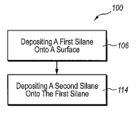
[0051] FIG. 2 is a flow diagram of an exemplary method 100 for forming
coating 26 according to at least one embodiment. As illustrated in this
figure, at 106
the first silane may be deposited onto surface 24. Adhesion promoting layer 28
may
be formed from the deposition of first silane onto surface 24. At 114, the
second
silane may be deposited onto the first silane and/or adhesion promoting layer
28.
Hydrophobic layer 30 may be formed from the deposition of the second silane
onto
the first silane and/or adhesion promoting layer 28. During 106, in which the
first
silane may be deposited onto surface 24, the first silane may be in a solid,
liquid, or
17
3771852_1.DOC
CA 02664536 2009-03-25
WO 2008/042986 PCT/US2007/080347
gaseous state. Deposition of the first silane onto surface 24 may be conducted
using
any suitable method, including for example, immersing surface 24 in a liquid
comprising the first silane and/or exposing surface 24 to a vapor comprising
the first
silane and/4r immersing surface 24 in a solution comprising the first silane.
Some
partial pressure of one or more inert gases may be present when the first
silane is
deposited on surface 24. In various embodiments, the first silane may be
deposited
under a pressure ranging from a few torr to above atmospheric pressure.
[00521 During or following 106, in which the first silane may be deposited
onto surface 24, the first silane may become bonded to surface 24. In at least
one
embodiment, the first silane may become covalently bonded to surface 24
through,
for example, a carbamate (i.e., urethane) linkage, an ester linkage, an ether
linkage,
an amide linkage, and/or a C-O-Si linkage. For example, a surface, such as a
surface
of a polymer substrate, may comprise a hydroxyl group.
[0053] In at least one example, a carbamate linkage may be formed
between the first silane and surface 24 by a reaction between a hydroxyl group
on
surface 24 and an isocyanate group on the first silane. In an additional
embodiment,
an ester linkage may be formed between the first silane and surface 24 by a
reaction
between a hydroxyl group on surface 24 and an acyl chloride group on the first
silane. In certain embodiments, an ether linkage may be formed between the
first
silane and surface 24 by a reaction between a hydroxyl group on surface 24 and
an
alkyl or benzyl chloride group on the first silane. In an additional
embodiment, an
ether linkage may be formed between the first silane and surface 24 by a
reaction
between a hydroxyl group on surface 24 and an epoxy or glycidyl group on the
first
silane. In an additional embodiment, an ester linkage may be formed between
the
first,silane and surface 24 by a reaction between a hydroxyl group on surface
24 and
18
3771852_1.DOC
CA 02664536 2009-03-25
WO 2008/042986 PCT/US2007/080347
a methyl ester group on the first silane. In an additional embodiment, a Si-O-
C
linkage may be formed between the first silane and surface 24 by a reaction
between
a hydroxyl group on surface 24 and a Si-Cl group, a Si-OCH3 group, a Si-
OCH2CH3
group, a Si-N(CH3)2 group, or a similar reactive group, on the first silane.
In an
additional embodiment, an amide linkage may be formed between the first silane
and
surface 24 by a reaction between a carboxyl group on surface 24 and an amine
group
on the first silane. In an additional embodiment, an ionic linkage may be
formed
between the first silane and surface 24 by a reaction between a carboxyl group
on
surface 24 and a primary amine group on the first silane to form an ion pair
of the -
COO- and -NH3+ groups. In an additional embodiment, an imine linkage may be
formed between the first silane and surface 24 by a reaction between a
carbanyl
group on surface 24 and an amine group on the first silane.
[0054] Alternatively, a siloxane linkage and/or a Si-O-C linkage may be
formed between the first silane and a surface of a silicon oxide based
substrate by,
for example, a reaction between a silane group on the first silane and a
silanol (Si-
OH) group on surface 24. An AI-O-Si linkage may also be formed between the
first
silane and a surface of an aluminum oxide based substrate by, for example, a
reaction between a silane group on the first silane and an A1OH group on
surface 24.
[0055] During 114, in which the second silane may be deposited onto the
first silane, the second silane may be in a solid, liquid, or gaseous state.
Deposition
of the second silane onto surface 24 may be conducted using any suitable
method,
including for example, immersing surface 24 in a liquid comprising the second
silane and/or exposing surface 24 to a vapor comprising the second silane. In
certain
embodiments, the second silane may be contained in a solution comprising a
solvent.
19
3771852_1.BOC
CA 02664536 2009-03-25
WO 2008/042986 PCT/US2007/080347
In various embodiments, the second silane film may be deposited under a
pressure
ranging from a few torr to above atmospheric pressure.
[0056] During or following 114, in which the second silane may be
deposited onto the first silane, the second silane may become bonded to the
first
silane. In at least one embodiment, the second silane may become covalently
bonded to the first silane through, for example, a siloxane (Si-O-Si) linkage.
A
siloxane linkage may be formed by a reaction between a silane group on the
second
silane and a silane group on the first silane. Prior to 114, a silane group on
the first
silane may be hydrolyzed to form a siloxyl (Si-OH) group. Subsequently, the
siloxyl
group on first silane may react with a silane group on the second silane to
form a
siloxane linkage.
[0057] In certain embodiments, prior to depositing the first silane onto
surface 24, surface 24 may be oxidized. For example, as illustrated in FIG. 3,
method 100 may further comprise 102 prior to 106. At 102, a portion of surface
24
may be oxidized. Surface 24 may be oxidized by, for example, exposing surface
24
to a plasma. In at least one embodiment, surface 24 may be oxidized by
exposing
surface 24 to an air plasma. Oxidation of surface 24 may introduce additional
hydroxyl and/or siloxyl groups to surface 24. Exposing surface 24 to a plasma
may
also clean organic matter from surface 24.
10058] In at least one embodiment, surface 24 may be oxidized by exposing
surface 24 to an oxygen plasma. Surface 24 may also be oxidized by exposing
surface 24 to a water plasma. In an additional embodiment, surface 24 may also
be
oxidized by exposing surface 24 to a plasma that contains oxygen and water. In
an
additional embodiment, surface 24 may be oxidized by exposing surface 24 to an
argon plasma, and subsequently exposing the surface to air or an oxygen
containing
3771952_1.DOC
CA 02664536 2009-03-25
WO 2008/042986 PCT/US2007/080347
gaseous composition. In an additional embodiment, surface 24 may be oxidized
by
exposing surface 24 to a helium plasma, and subsequently exposing the surface
to
the air. In an additional embodiment, surface 24 may be oxidized by exposing
surface 24 to an ultraviolet (UV) light. In an additional embodiment, surface
24 may
be oxidized by exposing surface 24 to a solution containing an oxidizing
agent.
[0059] In various embodiments, the first silane may be vaporized prior to
being deposited on surface 24. For example, as illustrated in FIG. 4, method
100
may further comprise 104 prior to 106. At 104, the first silane may by
vaporized to
form a vaporized first silane. At 106, the first silane may then be deposited
through
vapor deposition onto surface 24.
[0060] The first silane may be vaporized through any suitable method,
including, for example, increasing the temperature and/or reducing the
pressure of
the first silane. In certain embodiments, a carrier solvent may be used to
transport
the first silane into a heated vacuum chamber, where the first silane may be
vaporized. Substrate 22 may be present in a heated vacuum chamber in which the
first silane may be vaporized.
[0061] Vapor deposition of the first silane may enable effective deposition
and/or reaction of the first silane with surface 24, while reducing or
eliminating the
use of solvents to carry the first silane to desired portions of surface 24.
Accordingly, vapor deposition of the first silane may effectively minimize
solvent
and/or other waste products in comparison with a solution based delivery
system.
Additionally, vapor deposition of the first silane may reduce or eliminate any
need
for cleaning surface 24 and the deposited first silane prior to 114, in which
a second
silane may deposited onto the first silane.
21
3771852_1.DOC
CA 02664536 2009-03-25
WO 2008/042986 PCT/US2007/080347
[0062] In at least one embodiment, the first silane may be hydrolyzed
during or following deposition of the first silane onto surface 24. For
example, as
illustrated in FIG. 5, method 100 may further comprise 108 after 106 and prior
to
114. At 108, the first silane may be hydrolyzed. Hydrolyzing the first silane
may
comprise, for example, exposing the first silane to liquid or vaporized water
during
or following deposition of the first silane onto surface 24. In certain
embodiments,
hydrolyzing the first silane may comprise vaporizing water by raising the
water
temperature and/or reducing the water pressure, and exposing the first silane
deposited on surface 24 to the vaporized water. In various embodiments,
hydrolysis
may be conducted under a pressure ranging from a few torr to above atmospheric
pressure.
100631 Alternatively, hydrolysis may be promoted by water derived in-part
or exclusively from the substrate material and/or reaction by-products. For
example,
in a case where surface 24 comprises a surface of a polymeric substrate,
vaporized
water may be produced from a decomposition or reaction of the polymeric
substrate
during method 100. Additionally, water may be present in the substrate itself,
and
may be released during method 100. The vaporized water may in turn hydrolyze
the
first silane.
[0064] During hydrolysis of the first silane, at least one silanol group
(i.e.,
a Si-O-H group) may be formed on the first silane at the location of the
silane group.
The silanol group may act as an adhesion promoter for the second silane,
providing a
highly reactive site at which the second silane may bond to the first silane.
[0065] Hydrolysis of the first silane may lead to condensation between
molecular components of the first silane, forming siloxane bonds between
adjacent
molecular components. The siloxane bonds between adjacent molecular components
22
3771852_1.DOC
CA 02664536 2009-03-25
WO 2008/042986 PCT/US2007/080347
may result in cross-linking of the first silane deposited onto surface 24.
Siloxane
linkages between adjacent molecular components of the first silane may add
structural robustness to the first silane deposited on surface, enabling
formation of
an ultra-thin adhesion promoting layer 28, which is relatively stable and
abrasion
resistant, on surface 24.
[0066] In various embodiments, exposing the first silane to the vaporized
water may result in hydrolysis of at least one unreacted isocyanate group on
the first
silane, producing an amine group (i.e., -NH2). An amine group on the first
silane
may act as a Brransted-Lowry base, accepting protons and forming ionic bonds
with
carboxyl groups that may be present on surface 24. At elevated temperature,
the
amine group that has accepted a proton from a carboxyl group at the surface
may
form an amide linkage, with concomitant loss of water. The amine group may
also
form ionic bonds with silanol groups on the second silane deposited on the
first
silane. The amine group may also form ionic bonds with silanol groups in the
adhesion promoting layer 28.
[00671 In additional embodiments, the second silane may be vaporized
prior to being deposited on the first silane and/or adhesion promoting layer
28. For
example, as illustrated in FIG. 6, method 100 may further comprise 110
following
106 and prior to 114. At 110, the second silane may by vaporized to form a
vaporized second silane. At 114, the second silane may then be deposited
through
vapor deposition onto the first silane and/or adhesion promoting layer 28.
[0068] The second silane may be vaporized through any suitable method,
including, for example, increasing the temperature and/or reducing the
pressure of
the second silane. In certain embodiments, a carrier solvent may be used to
transport the second silane into a heated vacuum chamber, where the second
silane
23
3771852_1.DOC
CA 02664536 2009-03-25
WO 2008/042986 PCT/US2007/080347
may be vaporized. Substrate 22 may be present in a heated vacuum chamber in
which the second silane may be vaporized.
[0069] Vapor deposition of the second silane may enable effective
deposition and/or reaction of the second silane with the first silane while
reducing or
eliminating the use of solvents to carry the second silane to desired portions
of the
adhesion promoting layer 28. Accordingly, vapor deposition of the second
silane
may effectively minimize solvent and/or other waste products in comparison
with a
solution based delivery system. Additionally, vapor deposition of the second
silane
may reduce or eliminate any need for cleaning surface 24 and the deposited
second
silane following deposition of the second silane.
[0070] In various embodiments, after depositing the first silane onto
surface 24, the first silane may be cross-linked. For example, as illustrated
in FIG.
7, method 100 may further comprise 112 following 106. At 112, the first silane
may
be cross-linked.
[0071] Cross-linking of the first silane may be performed at any suitable
time following deposition of the first silane on the substrate, including, for
example,
prior to or following deposition of the second silane on the first silane.
Cross-
linking of the first silane may be promoted through any suitable method,
including,
for example hydrolysis of the first silane. As described above, at 108, the
first
silane may be hydrolyzed. Hydrolysis of the first silane may lead to
condensation
between molecular components of the first silane, forming siloxane bonds
between
adjacent molecular components. The siloxane bonds between adjacent molecular
components may result in cross-linking of the first silane deposited on
surface 24.
Siloxane linkages between adjacent molecular components of the first silane
may
add structural robustness to the first silane deposited on surface, enabling
formation
24
3771852_1.DOC
CA 02664536 2009-03-25
WO 2008/042986 PCT/US2007/080347
of an ultra-thin adhesion promoting layer 28, which is relatively stable and
abrasion
resistant, on surface 24.
[0072] In additional embodiments, a cross-linking compound may be used
to promote and/or increase cross-linking between molecular components of the
first
silane. Examples of cross-linking compounds suitable for use in cross-linking
the
first silane include, without limitation, bis(trichlorosilyl)hexane and
tetrakis(trichlorosilyethyl)-silane. The cross-linking compound may be bonded
to
molecular components of the first silane through any suitable means,
including, for
example, through hydrolysis. A cross-linking compound may promote increased
branching between molecular components of the first silane, and may increase
stability and abrasion resistance in adhesion promoting layer 28. In certain
embodiments, polymerizable groups such as, for example, vinyl groups, may be
introduced onto the first silane, and polymerization of the polymerizable
groups may
then be induced.
[0073] In various embodiments, after depositing the second silane onto
surface 24, the second silane may be cross-linked. For example, as illustrated
in
FIG. 8, method 100 may further comprise 116 following 114. At 116, the second
silane may be cross-linked.
[0074] Cross-linking of the second silane may be promoted through any
suitable method, including, for example hydrolysis of the second silane. In
certain
embodiments, the second silane may be hydrolyzed by exposing the second silane
to
vaporized water during or following deposition of the second silane onto the
first
silane. Alternatively, hydrolysis may be promoted by water derived in-part or
exclusively from the substrate material and/or reaction by-products. For
example, in
a case where surface 24 comprises a surface of a polymeric substrate,
vaporized
3771852_1.DOC
CA 02664536 2009-03-25
WO 2008/042986 PCT/US2007/080347
water may be produced from a decomposition or reaction of the polymeric
substrate
during method 100. Additionally, water may be present in the substrate itself,
and
may be released during method 100.
[0075] Hydrolysis of the second silane may lead to condensation between
individual molecular components of the second silane, as well as between
molecular
components of the second silane and the first silane. The condensation may
lead to
the formation of siloxane bonds between adjacent molecular components. The
siloxane bonds between adjacent molecular components may result in cross-
linking
of the second silane deposited onto surface 24. The siloxane bonds between
adjacent
molecular components may also result in cross-linking between the second
silane
and the first silane. Siloxane linkages between adjacent molecular components
of
the second silane and/or the first silane may add structural robustness to the
coating
composition, enabling an ultra-thin coating, which is relatively stable and
abrasion
resistant, to be deposited onto surface 24.
[0076] In additional embodiments, a cross-linking compound may be used
to promote and/or increase cross-linking between molecular components of the
second silane. Examples of cross-linking compounds suitable for use in cross-
linking the second silane include, without limitation,
bis(trichlorosilyl)hexane and
tetrakis(trichlorosilyethyl)-silane. The cross-linking compound may be bonded
to
molecular components of the second silane through any suitable means,
including,
for example, through hydrolysis. A cross-linking compound may promote
increased
branching between molecular components of the second silane, and may increase
stability and abrasion resistance in a coating of the second silane. In
certain
embodiments, polymerizable groups such as, for example, vinyl groups, may be
26
3771852_f .770C
CA 02664536 2009-03-25
WO 2008/042986 PCT/US2007/080347
introduced onto the second silane, and polymerization of the polymerizable
groups
may then be induced.
[0077] In certain embodiments, after depositing the first silane onto surface
24 and/or after depositing the second silane onto the first silane, the first
silane
and/or the second silane may be cured. For example, as illustrated in FIG. 9,
method
100 may further comprise 118 following 114. 118 may comprise curing the second
silane and/or the first silane to form a cured coating 26 on surface 24. The
term
"cure," "cured," or "curing" as used herein, refers to a change in state,
condition,
and/or structure of a material, and may include partial as well as complete
curing.
[0078] Curing of the first silane and/or the second silane may be conducted
using any suitable method, including, for example, exposing the first silane
and/or
the second silane to heat or radiation. In an exemplary embodiment, a coating
comprising the first silane and the second silane may be cured by exposing the
coating to an elevated temperature for a suitable period of time.
[0079] FIGS. 10A-lOD show exemplary hearing aid devices according
various embodiments. As illustrated in these figures, a hearing aid device 200
may
comprise a device cover 202, a microphone cover 204, and a battery door 208.
In at
least one embodiment, as illustrated in FIG. 10A, hearing aid device 200 may
be an
open ear hearing aid. As shown in FIG. 10A, hearing aid device 200 may
comprise a
device cover 202, at least two microphone covers 204 (e.g., covering a front
microphone and a rear microphone), a program button 214, tubing 210, an in-the-
ear
dome 216, and a sound port 220. Microphone covers 204 may comprise a mesh
material. FIG. 10D shows an exemplary battery compartment 222 on a portion of
hearing aid device 200, such as an open ear hearing aid. Battery compartment
222
27
3771852 I.DOC
CA 02664536 2009-03-25
WO 2008/042986 PCT/US2007/080347
may comprise a battery door 208, and a battery 224. The battery compartment
222
in FIG. 10D is shown in an open configuration.
[0080] In an additional embodiment, as illustrated in FIG. IOB, hearing aid
device 200 may be a behind the ear (BTE) hearing aid. As shown in FIG. IOB,
hearing aid device 200 may comprise a device cover 202, a battery door 208, a
program button 214, a volume control 206, tubing 210, an ear hook 212, and an
ear
mold 218.
[0081] In an additional embodiment, as illustrated in FIG. 10C, hearing aid
device 200 may be a custom hearing aid. As shown in FIG. 1013, hearing aid
device
200 may comprise a device cover 202, a microphone cover 204, a battery door
208,
and a sound port 220. Custom hearing aids may be designed to fit within a
portion
of the ear or canal. Examples of custom hearing aids include, without
limitation,
CIC (Completely in the Canal), MC (Mini Canal), ITC (In the Canal), ITE (In
the
Ear); and HS (Half Shell) hearing aids. Microphone cover 204 may comprise a
mesh
material.
[0082] Hearing aid device 200 may comprise coating 26 on, near, or
adjacent to any suitable portion, including external and internal portions of
hearing
aid device 200. Additionally, any suitable component or portion thereof may
comprise coating 26. Coating 26 may be formed on, near, or adjacent to any
portion
of hearing aid device 200 that may having an opening between an exterior
portion
and an interior portion of hearing aid device 200. Examples of portions of
hearing
aid device 200 that coating 26 may be formed on, near, or adjacent to include,
without limitation, device cover 202, microphone cover 204, volume control
206,
battery door 208, tubing 210, ear hook 212, program button 214, in-the-ear
dome
216, ear mold 218, sound port 220, battery compartment 222, and/or battery
224.
28
3771852_1.DOC
CA 02664536 2009-03-25
WO 2008/042986 PCT/US2007/080347
[0083] FIG. 11 is an exemplary silicon-based article, on a portion of which
a coating is formed according to an additional embodiment. As illustrated in
this
figure, a silicon-based article 300 may include a substrate 322 and a
substrate
surface 324. Coating 26 may be formed on a surface portion of substrate 322,
including, for example, substrate surface 324. Examples of silicon-based
article 300
include, without limitation, silicon wafers, semiconductor devices, and
integrated
circuits. Silicon-based articles 300 may comprise any suitable material,
including,
for example, silicon and/or silicon oxide.
EXAMPLES
[0084] The following examples are for illustrative purposes only and are
not meant to be limiting on the scope of the appended claims.
Renents
[0085] Reagents used in the following examples include: (Tridecafluoro-
1,1,2,2-tetrahydrooctyl)trichlorosilane (? 97 %, Aldrich), 3-
isocyanatopropyltriethoxysilane (95 %, Gelest, Morrisville, PA), triethoxy(1H,
IH,
2H, 2H-perfluorooctyl)silane (98%, Aldrich), m-cresol (97%, Aldrich), and
nylon
6/6 pellets (Aldrich, Cat. No. 181129). An "aqueous salt/acid" solution
employed
herein is a formulation for artificial sweat, which was 0.34 M NaCI, 0.08 M
urea,
0.33 M NH4C1, 0.04 M CH3COOH and 0.12 M lactic acid. The solution was
adjusted to pH 4.7 with 2 M NaOH.
Substrates
[0086] Substrates used in the following examples included silicon
substrates, reinforced nylon substrates, and spin-coated nylon substrates.
Silicon
substrates used in the examples included silicon wafers (test grade, n-type,
<1-0-0>
29
3771852_1.DOC
CA 02664536 2009-03-25
WO 2008/042986 PCT/US2007/080347
orientation, 2-6 S2-cm) from UniSil Corporation, California. The silicon
wafers were
cleaved into ca. 1.5 x 1.5 cm pieces. Prior to performing any surface
chemistry on
the silicon substrates, the silicon substrates were cleaned with an aqueous 2%
sodium dodecyl sulfate ("SDS") solution and water without sonication.
[0087] Reinforced nylon substrates used in the following examples
included FDA grade reinforced nylon 6/6 surfaces containing 35% chopped glass
fiber by weight (1/8-3/16" long). The FDA grade reinforced nylon surfaces
contained FDA compliant additives (e.g., colorants) and no UV or high flow
additives. Aldrich indicated the melting point of the nylon 6/6 they provided
was
263 C, and its glass transition temperature was 45 C. Prior to performing any
surface chemistry on the reinforced nylon substrates, the reinforced nylon
substrates
were sonicated in an SDS solution for 5 minutes. They were then sonicated in
deionized water for 10 minutes. This water was changed three times during
sonication.
[0088] Spin-coated nylon substrates used in the following examples
included substrates prepared by spin-coating a solution of nylon 6/6 pellets
in m-
cresol onto surfaces of native oxide coated silicon wafers using the following
program conditions (on an instrument from Laurell Technologies Corporation,
model
WS-400B-6NPP/LITE): 1000 rpm (10 seconds) followed by 5000 rpm (90 seconds).
An initial concentration of the nylon 616 solution was < 3% (w/w), but this
nylon 6/6
solution was diluted in rn-cresol until the spin-coating process obtained a
film
thickness of approximately 170 A. The spin-coated nylon substrates were then
baked in a vacuum oven at 100 C for 2 hours at reduced pressure to drive off m-
cresol.
Surface Analytical Instrumentation
377I852_I.DQC
CA 02664536 2009-03-25
WO 2008/042986 PCT/US2007/080347
[0089] Time-of-flight secondary ion mass spectrometry ("TOF-SIMS") was
performed with an ION-TOF (TOF-SIMS IV) instrument with a two-lens,
monoisotopic 69Ga+ gun as a primary ion source. X-ray photoelectron
spectroscopy
("XPS") was performed with an SSX-100 instrument from Surface Sciences using
an
Al Ka source and a hemispherical analyzer. An electron flood gun was employed
for
charge compensation of the reinforced nylon samples, and this charge
compensation
was further enhanced by placing a fine Ni mesh ca. 0.5 - 1.0 mm above the
surface
of the glass reinforced polymer. No charge compensation was necessary for the
silicon or spin-coated nylon on silicon samples. Water contact angles were
measured with a Rame -Hart (model 100-00) contact angle goniometer.
Spectroscopic ellipsometry was performed with an M-2000 instrument from the
J.A.
Woollam Co., Inc. The wavelength range was 190.5 - 989.4 nm, and the angle of
incidence was fixed at 75 . Silicon oxide, hydrocarbon, deposited silane
films, and
spin coated nylon were modeled using the same optical constants of silicon
oxide
that were found in the instrument software.
Example 1. Plasma Cleaning/Treatment of Silicon Substrate
[0090] Plasma cleaning/treatment of silicon substrates was performed by
exposing the silicon substrates to an air plasma in a plasma cleaner (model
PDC-32G
from Harrick Plasma, Ithaca, NY) at medium power (10.5 W applied to the RF
coil)
for 30 seconds. An advancing water contact angle (0a(H2O)) for a silicon
substrate
surface was measured to be 40 prior to plasma cleaning/treatment. Following
plasma cleaning/treatment, an average advancing water contact angle for a
surface of
silicon substrate prepared according to this example was measured to be <15 .
[0091] Advancing water contact angle may be used as a measure of surface
hydrophobicity. A higher advancing water contact angle for a surface may
indicate
31
3771852_1.DOC
CA 02664536 2009-03-25
WO 2008/042986 PCT/US2007/080347
that the surface has a higher degree of hydrophobicity. A decrease in water
contact
angle for a surface following plasma cleaning/treatment may indicate an
increase in
oxygen content (e.g., -OH content) of the surface. A decrease in water contact
angle
for a surface following plasma cleaning/treatment may also indicate removal of
hydrocarbon contamination from the surface as a result of the plasma
cleaning/treatment.
Example 2. Plasma Cleaning/Treatment of Reinforced Nylon Substrate
[0092] Plasma cleaning/treatment of reinforced nylon substrates was
performed by exposing the reinforced nylon substrates to an air plasma in a
plasma
cleaner (model PDC-32G from Harrick Plasma, Ithaca, NY) at medium power (10.5
W applied to the RF coil) for 30 seconds.
[0093] An average advancing water contact angle for surfaces of three
reinforced nylon substrates was measured to be 69 prior to plasma
cleaning/treatment. Following plasma cleaning/treatment, an average advancing
water contact angle for surfaces of five reinforced nylon substrates prepared
according to this example was measured to be 32 .
[0094] Prior to plasma cleaning/treatment of a reinforced nylon substrate
prepared according to this example, an X-ray photoelectron spectrum ("XP
spectrum") for the reinforced nylon substrate surface, obtained using XPS, was
dominated by signals from oxygen (Ol s), nitrogen (Nl s), and carbon (C l s).
Following plasma cleaning/treatment of the reinforced nylon substrate, Ols,
Nls,
and C 1 s signals still dominated the XP spectrum for the reinforced nylon
substrate
surface. However, a peak ratio of O 1 s to C 1 s for the reinforced nylon
substrate
surface increased significantly, from a ratio of 0.14 prior to plasma
cleaning/treatment to a ratio of 0.28 following plasma cleaning/treatment,
which
32
3771852_1.DOC
CA 02664536 2009-03-25
WO 2008/042986 PCT/US2007/080347
indicates an increase in oxygen (e.g., -OH) content of the reinforced nylon
substrate
surface following plasma cleaning/treatment. Additionally, the C 1s narrow
scan of
the XP spectrum for the reinforced nylon substrate surface showed a notable
increase
in a peak representing oxidized (i.e., chemically shifted) carbon, further
indicating
an increase in oxygen content of the reinforced nylon substrate following
plasma
cleaning/treatment.
[0095] The O"/C` ratio in a negative ion TOF-SIMS spectrum of a
reinforced nylon substrate surface prepared according to this example was 0.09
prior
to plasma cleaning/treatment and was 0.21 following plasma cleaning/treatment,
indicating an increase in oxygen content of the reinforced nylon substrate
surface as
a result of the plasma cleaning/treatment.
Example 3. Plasma Cleaning/Treatment of Spin Coated Nylon Substrate
[0096] Plasma cleaning/treatment of spin-coated nylon substrates was
performed by exposing the spin-coated nylon substrates to an air plasma in a
plasma
cleaner (model PDC-32G from Harrick Plasma, Ithaca, NY) at medium power (10.5
W applied to the RF coil) for 30 seconds.
[0097] An average advancing water contact angle for surfaces of five spin-
coated nylon substrates was measured to be 60 prior to plasma
cleaning/treatment.
Following plasma cleaning/treatment, an average advancing water contact angle
for
surfaces of six spin-coated nylon substrates prepared according to this
example was
measured to be 34 .
Example 4._Prep_aration of NCO-silane/Silicon Substrate
[0098] Following plasma cleaning/treatment according to Example 1,
silicon substrates were dehydrated in a vacuum oven at 100 C at reduced
pressure.
33
3771852_1.1-JOC
CA 02664536 2009-03-25
WO 2008/042986 PCT/US2007/080347
The vacuum for the vacuum oven was provided by a rotary vane pump. The vacuum
oven contained a dry ice/acetone-cooled glass trap that prevented back-
streaming of
oil from the rotary vane pump and prevented both solvents and reagents from
entering the rotary vane pump. After introducing the silicon substrates into
the
oven, the rotary vane pump was turned on for 3 minutes to attain a pressure of
15
Torr, and the valve to the rotary vane pump was then closed. The surfaces were
allowed to dehydrate under these conditions for 30 minutes. The rotary vane
pump
was then turned on again for 3 minutes to pump off water vapors, after which
the
valve to the rotary vane pump was again closed.
[0099] An aliquot of 250 L of 3-isocyanatopropyltriethoxysilane ("NCO-
silane") was then injected into the vacuum oven through a septum. The NCO-
silane
evaporated rapidly after being injected into the vacuum oven. The surfaces
were
allowed to react with the vapors of the NCO-silane under essentially static
conditions for 30 minutes to form a silicon substrate having NCO-silane
deposited
on it ("NCO-silane/silicon substrate"). The valve to the rotary vane pump was
then
opened to pump off unreacted NCO-silane. Following plasma cleaning/treatment,
an
average advancing water contact angle for three NCO-silane/silicon substrates
prepared according to this example was measured to be 82 .
[00100] Prior to deposition of NCO-silane on a silicon substrate, no N1s
signal could be observed in an XP spectrum of the silicon substrate surface.
Following deposition of NCO-silane on the silicon substrate to form an NCO-
silane/silicon substrate surface according to this example, a small N1s signal
was
observable in an XP spectrum of the NCO-silane/silicon substrate surface.
Spectroscopic ellipsometry of the NCO-silane/silicon substrate surface
indicated that
a layer having a thickness of 9.5 A was present on the silicon substrate
surface.
34
3771852_1.DOC
CA 02664536 2009-03-25
WO 2008/042986 PCT/US2007/080347
Example 5. Preparation of NCO-silane/Reinforced Nylon Substrate
[00101] The procedure described for Example 4 was essentially followed
with the exception that a reinforced nylon substrate prepared according to
Example 2
was used instead of a silicon substrate to form a reinforced nylon substrate
having
NCO-silane deposited on it ("NCO-silane/reinforced nylon substrate").
Following
deposition of NCO-silane, an average advancing water contact angle for five
NCO-
silane/reinforced nylon substrates prepared according to this example was
measured
to be 87 .
Example 6. Preparation of NCO-silane/Spin-Coated Nylon Substrate
[00102] The procedure described for Example 4 was essentially followed
with the exception that a spin-coated nylon substrate prepared according to
Example
3 was used instead of a silicon substrate to form a spin-coated nylon
substrate
having NCO-silane deposited on it ("NCO-silane/spin-coated nylon substrate").
Following NCO silane deposition and plasma cleaning/treatment, the average
advancing water contact angle for six NCO-silane/spin-coated nylon substrates
prepared according to this example was measured to be 82 .
Examnle 7. Hydrolysis of NCO-silane/Silicon Substrate
[00103] NCO-silane/silicon substrates prepared according to Example 4
were left in a vacuum oven, and a Petri dish containing 5 ml of water was
introduced
into the vacuum oven. The door to the oven was closed and the NCO-
silane/silicon
substrates were allowed to hydrolyze at atmospheric pressure and 100 C for 30
minutes to form NCO-silane/silicon substrates having hydrolyzed surfaces
("hydrolyzed NCO-silane/silicon substrates").
Example_8. Hydrolysis of NCO-silane/Reinforced Nylon Substrate
3771852W1.DaC
CA 02664536 2009-03-25
WO 2008/042986 PCT/US2007/080347
[001041 NCO-silane/reinforced nylon substrates prepared according to
Example 5 were left in a vacuum oven, and a Petri dish containing 5 ml of
water was
introduced into the vacuum oven. The door to the oven was closed and the NCO-
silane/reinforced nylon substrates were allowed to hydrolyze at atmospheric
pressure
and 100 C for 30 minutes to form NCO-silane/reinforced nylon substrates having
hydrolyzed surfaces ("hydrolyzed NCO-silane/reinforced nylon substrates").
Example 9. Hydrolysis of NCO-silane/Spin-Coated Nylon Substrate
[00105] NCO-silane/spin-coated nylon substrates prepared according to
Example 6 were left in a vacuum oven, and a Petri dish containing 5 ml of
water was
introduced into the vacuum oven. The door to the oven was closed and the NCO-
silane/spin-coated nylon substrates were allowed to hydrolyze at atmospheric
pressure and 100 C for 30 minutes to form NCO-silane/spin-coated nylon
substrates
having hydrolyzed surfaces ("hydrolyzed NCO-silane/spin-coated nylon
substrates").
Example 10. Preparation of Rf-NCO-Silane/Silicon Substrate
[00106] Hydrolyzed NCO-silane/silicon substrates prepared according to
Example 7 were placed in a desiccator along with an open vial of
(tridecafluoro-
1,1,2,2-tetrahydrooctyl)trichlorosilane ("Rf-silane") for 16 hours. The
hydrolyzed
NCO-silane/silicon substrates were then removed from the desiccator and cured
in
an oven at 80 C for 1 hour to form NCO-silane/silicon substrates having Rf-
silane
deposited on their surfaces ("Rf-NCO-silane/silicon substrates").
Spectroscopic
ellipsometry indicated that an average surface thickness of hydrolyzed NCO-
silane/silicon substrates was 29.1 A prior to exposure to Rf-silane and was
78.2 A
following exposure to Rf-silane to form Rr-NCO-silane/sil'zcon substrates
according
to this example. The notable increase in thickness of the surfaces following
36
3771852_1.DOC
CA 02664536 2009-03-25
WO 2008/042986 PCT/US2007/080347
exposure to Rf-silane may indicate cross-linking of Rf--silane molecules into
a
polymeric thin film on the substrate surfaces.
Example 11. Preparation of Rf-NCO-silane/ReinforcedNylon Substrate
[00107] Hydrolyzed NCO-silane/rein.forced nylon substrates prepared
according to Example 8 were placed in a desiccator along with an open vial of
Rf-
silane for 16 hours. The hydrolyzed NCO-silane/reinforced nylon substrates
were
then removed from the desiccator and cured in an oven at 80 C for 1 hour to
form
NCO-silane/reinforced nylon substrates having Rf-silane deposited on their
surfaces
("Rf-NCO-silane/reinforced nylon substrates").
la [00108] An XPS analysis of an Rf-NCO-silane/reinforced nylon substrate
prepared according to this example showed that an F 1 s signal, with its
accompanying F Auger peaks, was the dominant signal in the XP spectrum. A
split
carbon signal was observed and indicated the presence of i) carbon bonded to
carbon
and/or hydrogen and/or mildly oxidized carbon at lower binding energy, and ii)
carbon in CF2 groups at higher binding energy, where each F atom bonded to a C
atom is known to shift the C I s signal by ca. 2.9 eV, and secondarily shift
carbon
atoms by ca. 0.7 eV. No N Is signal was observable in the XP spectrum,
indicating
that the Rf-silane may have formed a film that was free from pinhole defccts
and/or
that was relatively thick in all places. A small oxygen signal was also
present in the
XP spectrum, which would be expected from Si-O linkages.
Example 12. Preparation of Rf-NCO-silane/Sgin-Coated Nylon Substrate
[00109] Hydrolyzed NCO-silane/spin-coated nylon substrates prepared
according to Example 9 were placed in a desiccator along with an open vial of
Rf-
silane for 16 hours. The hydrolyzed NCO-silane/spin-coated nylon substrates
were
37
3771 S52_1.DOC
CA 02664536 2009-03-25
WO 2008/042986 PCT/US2007/080347
then removed from the desiccator and cured in an oven at 80 C for 1 hour to
form
NCO-silane/ spin-coated nylon substrates having Rf-silane deposited on their
surfaces ("Rf-NCO-silane/spin-coated nylon substrates"). Spectroscopic
ellipsometry indicated that a surface thickness of a hydrolyzed NCO-
silane/spin-
coated nylon substrate was 125.9 A prior to exposure to Rf-silane and was
272.3 A
following exposure to Rf -silane to form a Rf-NCO-silane/spin-coated nylon
substrate according to this example. The notable increase in thickness of the
surfaces following exposure to Rf-silane may indicate crosslinking of Rf-
silane
molecules into a polymeric thin film on the substrate surfaces.
Example 13. Abrasion Testing of Rt-NCO-silane/Reinforced Nylon Substrate
[00110] An abrasion apparatus for testing abrasion resistance consisted of an
electrical drill (Craftsman, Model No. 315.101160) that was clamped vertically
relative to a bench top. A commercially available polishing disk (Craftsman),
which
is designed to be used with an electric drill, was attached to the chuck of
the drill,
and a piece of abrasive felt (15 cm x 14.7 cm) was pasted onto the polishing
disk.
When the drill was turned on, it caused the felt disk to rotate parallel to
the bench
top. A sample holder was made from two rectangular strips of plywood joined
end-
to-end with a steel hinge. The end of one of the rectangular strips was
clamped to a
stand, and a sample was attached to the end of the other rectangular strip
with
double-sided tape. The sample was then placed on the felt wheel 4.5 cm from
its
center, and remained in contact with the felt wheel as the felt wheel rotated.
A brass
cylinder weighing 164 g was placed directly above the sample on the wood
strip.
The rotational speed of the drill was controlled with a powerstat and the felt
was
also marked on its edge so as to count the number of cycles during the
abrasion tests,
38
3771852_1.DOC
CA 02664536 2009-03-25
WO 2008/042986 PCT/US2007/080347
[001111 Additionally, a reinforced nylon substrate was plasma
cleaned/treated according to Example 2. Following plasma cleaning/treatment,
the
reinforced nylon substrate was hydrolyzed with a similar surface that had been
treated with the NCO silane, and then placed in a desiccator along with an
open vial
of (tridecafluoro- 1, 1,2,2-tetrahydrooctyl)trichlorosi lane for 16 hours. The
reinforced nylon substrate was then removed from the desiccator and cured in
an
oven at 80 C for 1 hour to form reinforced nylon substrates having Rf-silane
deposited on its surface, with no NCO-silane between the Rf-silane and the
surface
of the reinforced nylon substrate.
[00112] An Rf-NCO-silane/reinforced nylon substrate prepared according to
Example 11 and the reinforced nylon substrate containing Rf-Silane and no NCO-
silane were each tested using the abrasion apparatus. After more than 430
cycles in
the abrasion testing apparatus, the advancing water contact angle of the
surface of
the Rf-NCO-silane/reinforced nylon substrate prepared according to Example 11
was
10 higher than the advancing water contact angle of the surface of the
reinforced
nylon substrate containing Rf-Silane and no NCO-silane.
[00113] An XP spectrum of the substrate surfaces following abrasion testing
indicated that the ratio of C:F for the Rf-NCO-silane/reinforced nylon
substrate
prepared according to Example 11 was 43:57, while the C:F ratio for the
reinforced
nylon substrate containing Rf-Silane and no NCO-silane was 49:51, indicating a
higher concentration of Rf-silane on the surface of the Rf-NCO-
silane/reinforced
nylon substrate prepared according to Example 11. The narrow scan of the XP
spectra shows a peak for C attached to F atoms is comparatively larger in
intensity
for the surface of Rf-NCO-silane/reinforced nylon substrate prepared according
to
Example 11, further indicating a higher concentration of Rf-silane on the
surface.
39
3771852 1.DOC
CA 02664536 2009-03-25
WO 2008/042986 PCT/US2007/080347
Example 14. TOF-SIMS Analysis of Substrate Surfaces
[00114] TOF-SIMS analysis in both the negative and positive ion modes was
performed on silicon oxide, reinforced nylon, and spin-coated nylon substrates
after
treatment with the NCO-silane, and again after treatment with the Rf--silane.
TOF-
SIMS analysis, which has an information depth of only about 2 nm, is typically
more
surface sensitive than XPS analysis, which probes at least 10 nm into a
material.
Positive ion TOF-SIMS spectra of a Rf-NCO-silane/silicon substrate prepared
according to Example 10, a Rf-NCO-silane/reinforced nylon substrate prepared
according to Example 11, and a Rf-NCO-silane/spin-coated nylon substrate
prepared
according to Example 10 each showed a series of peaks that are characteristic
of a
perfluorinated hydrocarbon. The two largest peaks in the TOF-SIMS spectra were
identified as the CF} and CF3+ peaks. The negative ion spectra from the RF-NCO-
silane/silicon substrate, the Rf-NCO-silane/reinforced nylon substrate, and
the Rf-
NCO-silane/spin-coated nylon substrate were dominated by a single F peak, and
also showed an F2- peak, which is typically less than 5% intense as the F
signal.
Example 15. Analysis of Surface Layer Thickness
[00115] Plasma treated silicon substrates and spin-coated nylon substrates,
each having no NCO-silane deposited on the surfaces, were hydrolyzed. Silicon
substrates and spin-coated nylon substrates with NCO-silane deposited on their
surfaces were also hydrolyzed. Each of the substrates in this example were
then
placed in a desiccator along with an open vial of Rf-silane for 16 hours,
after which
they were cured in an oven at 80 C for 1 hour.
[00116] Spectroscopic ellipsometry indicated that surfaces of the silicon
substrates having no NCO-silane deposited on them had an average coating
thickness
of 116.7 A, and surfaces of the spin-coated substrates having no NCO-silane
37718s2_1.DOC
CA 02664536 2009-03-25
WO 2008/042986 PCT/US2007/080347
deposited on them had an average coating thickness of 232.7 A. Spectroscopic
ellipsometry indicated that surfaces of the silicon substrates with NCO-silane
deposited on them had an average coating thickness of 48.0 A, and surfaces of
the
spin-coated substrates having NCO-silane deposited on them had an average
coating
thickness of 67.0 A. Accordingly, the spectroscopic ellipsometry analysis
indicates
that the surfaces coated with the NCO-silane were considerably thinner than
the
surfaces that were not treated with the NCO.
Example 16. Plasma Cleaninji/Treatment of Reinforced N,ylon Substrate using
YES System
[00117] Reinforced nylon substrates were cleaned/treated in 02 plasma
using a YES 1224 P Chemical Vapor Deposition System manufactured by Yield
Engineering Systems, Inc., California ("YES System"). Various time periods
were
used. Table 1 shows advancing water contact angles for reinforced nylon
substrates
exposed to 02 plasma for various time periods according to this example.
Table 1
Plasma Advancing
treatment time water contact
(minutes) angle (0a(Hz0))
1 47
2.5 450
5 370
7.5 34
Example 17. Preparation of NCO-silane/Silicon Substrate usinLFYES System
[0011$] Silicon substrates were cleaned/treated in 02 plasma for 6 minutes
using the YES System. The silicon substrates were then exposed to NCO-silane
vapor for 10 minutes at a temperature of 100 C to form an NCO-silane/silicon
substrate. An advancing water contact angle for an NCO-silane/silicon
substrate
41
3771852_1.DOC
CA 02664536 2009-03-25
WO 2008/042986 PCT/US2007/080347
prepared according to this example was measured to be 55 . Spectroscopic
ellipsometry of a silicon substrate surface and an NCO-silane/silicon
substrate
surface prepared according to this example indicated an increase in the
thickness of
the silicon substrate surface of 11.8 A as a result of the NCO-silane
deposition.
Example 18. Preparation of NCO-silane/Reinforced Nylon Substrate usin2 YES
System
[00119] Reinforced nylon substrates were cleaned/treated in 02 plasma for 6
minutes using the YES System. The reinforced nylon substrates were then
exposed
to NCO-silane vapor for 10 minutes at a temperature of 100 C to form an NCO-
silane/reinforced nylon substrate. An advancing water contact angle for an NCO-
silane/reinforced nylon substrate prepared according to this example was
measured
to be 76 .
Example 19. Preparation of RrNCO-silane/Silicon Substrate using YES System
[00120] Following preparation of NCO-silane/silicon substrates according to
Example 17, 3 mL of water was introduced into a chamber in the YES system to
produce water vapor in the chamber. The NCO-silane/silicon substrates were
hydrolyzed by exposing them to the water vapor in the chamber for 30 minutes
at a
temperature of 100 C. The NCO-silane/silicon substrates were then exposed to
Rf-
NCO-silane vapor for 15 minutes at a temperature of 100 C to form Rf-NCO-
silane/silicon substrates. An advancing water contact angle for an Rf-NCO-
silane/silicon substrate prepared according to this example was measured to be
125 .
Example 20. Preparation of Rf-NCO-silane/Reinforced Nylon Substrate using
YES System
42
3771852_1.AOC
CA 02664536 2009-03-25
WO 2008/042986 PCT/US2007/080347
[00121] Following preparation of NCO-silane/reinforced nylon substrates
according to Example 18, 3 mL of water was introduced into a chamber
containing
the NCO-silane/reinforced nylon substrates in the YES system to produce water
vapor in the chamber. The NCO-silane/reinforced nylon substrates were
hydrolyzed
by exposing them to the water vapor in the chamber for 30 minutes at a
temperature
of 100 C. The NCO-silane/reinforced nylon substrates were then exposed to Rf-
silane vapor for 15 minutes at a temperature of 100 C to form Rf-NCO-
silane/reinforced nylon substrates. An average advancing water contact angle
for Rf-
NCO-silane/reinforced nylon substrates prepared according to this example was
measured to be 155 .
[00122] The preceding description has been provided to enable others
skilled in the art to best utilize various aspects of the exemplary
embodiments
described herein. This exemplary description is not intended to be exhaustive
or to
be limited to any precise form disclosed. Many modifications and variations
are
possible without departing from the spirit and scope of the instant
disclosure. The
embodiments described herein are in all respects illustrative and not
restrictive.
[00123] Unless otherwise noted, the terms "a" or "an," as used in the
specification and claims, are to be construed as meaning "at least one of." In
addition,
for ease of use, the words "including" and "having," as used in the
specification and
claims, are interchangeable with and have the same meaning as the word
"comprising."
43
3771852_1.DOC