Note: Descriptions are shown in the official language in which they were submitted.
CA 02664555 2009-03-25
WO 2008/039760 PCT/US2007/079401
-1-
LOCK MECHANISM FOR PIN CLAMP ASSEMBLY
TECHNICAL FIELD
The present disclosure is generally related to gripper or clamp
assemblies. More particularly, the present disclosure as related to pin clamp
assemblies having a locking mechanism that selectively limits movement of the
clamp's locating pin.
BACKGROUND AND SUMMARY
Pin clamps which use locating pins and movable fingers to engage and
grip a workpiece are known. Characteristically, such pin clamps employ either
a
stationary or rectilinearly moving locating pin with [a] movable finger[s]
located
therein. Clamps having the rectilinearly movable locating pin extend the
locating pin
to engage a hole in a workpiece, such as a metal sheet. The locating pin then
retracts
and the finger or fingers within the locating pin extend and hold the
workpiece against
the clamp's body. In an operating environment, it would be useful to have a
locking
mechanism that can hold the movable locating pin. Under a loss of air
pressure, for
example, the locating pin would still hold the workpiece.
Accordingly, an embodiment of the present disclosure provides a pin
clamp assembly which comprises a housing, a locating pin, a body, and first
and
second locks. The locating pin extends from the housing. The body extends from
the
locating pin. At least a portion of the body is located interior of the
housing. The
body and locating pin are movable with respect to the housing. The first lock
is
located on the body and the second lock is configured to selectively couple
with the
first lock. Selective coupling of the locks prevent the body from moving under
a loss
of actuation pressure.
In the above and other embodiments, the pin clamp assembly may
further comprise: a rod that is movable upon initiation of an actuation force
and that
moves the body; the first lock being a hook that is coupled to the body; the
second
lock being a catch that couples with the hook; the second lock being
selectively
CA 02664555 2009-03-25
WO 2008/039760 PCT/US2007/079401
-2-
movable with respect to the housing; the catch being movable along a parallel
path of
movement with the body to allow the catch to couple with the hook at different
locations; a bracket attached to the rod and moves with the rod to disengage
the locks
to allow the body to move; a bracket that moves to disengage the locks prior
to the
rod moving the body; a bracket attached to, and movable with, the rod, wherein
the
bracket comprises at least one surface that engages the hook to move the same
from
the catch as the rod moves, to allow the body to move; the hook further
comprising at
least one dowel that selectively engages the surface of the bracket oriented
non-
perpendicular to movement of the body to release the hook from the catch; and
the
catch further comprising an angled surface that is engagable by the hook but
does not
prevent the body from moving.
Another illustrative embodiment of the pin clamp assembly includes a
movable locating pin and a lock assembly. The lock assembly comprises a hook
and
a latch that selectively engages and holds each other to restrict movement of
the
locating pin.
In the above and other embodiments, the pin clamp assembly may
further comprise: a housing that receives a portion of the locating pin; the
catch being
selectively adjustable relative to the housing; the hook being pivotable
relative to the
locating pin; an actuator that moves the locating pin; and the locating pin
being
movable between extended and retracted positions, and wherein the lock
assembly
holds the locating pin in the retracted position.
A method of selectively holding and locking a workpiece with a
locating pin clamp is also provided. The method comprising the steps of:
providing a
locating pin that engages a workpiece; retracting the locating pin; holding
the
workpiece with at least one finger extending from the locating pin; latching
the
locating pin by coupling a first hook associated with the locating pin with
and a
second hook to prevent release of the workpiece by the finger.
Additional features and advantages of the pin clamp assembly will
become apparent to those skilled in the art upon consideration of the
following
CA 02664555 2011-04-07
71984-54
3
detailed description of the illustrated embodiments exemplifying the best mode
of
carrying out the pin clamp assembly as presently perceived.
According to another aspect of the invention, there is provided a pin
clamp assembly for holding a workpiece, the pin clamp assembly comprising a
movable locating pin with a finger that is extendable therefrom, a housing
that
receives a portion of the locating pin and has a workpiece support adjacent
the
extended finger, and a lock assembly which comprises a hook and a catch that
selectively engages and holds each other to restrict movement of the locating
pin,
and further comprising an unlock bracket; wherein the unlock bracket includes
an
angled surface configured to engage a pin extending from the hook to cause the
hook to pivot and unlatch from the catch; the hook and catch are configured to
maintain a hold with each other under loss of actuation force, or if the
locating pin is
pulled on; wherein the hook and catch are further configured such that the
hook,
using a spring, is biased against an angled surface of the catch as the
locating pin
moves in a first direction; wherein as the locating pin continues to move in
the first
direction, the hook latches with the catch to hold the locating pin in place;
to release
the lock assembly, the unlock bracket is movable in a second direction such
that a
surface on the unlock bracket engages a pin coupled with the hook; movement of
the
unlock bracket in the second direction pivots the hook against the bias of the
spring;
wherein pivoting of the hook begins unlatching it from the catch; continued
movement
of the unlock bracket unlatches the hook from the catch.
CA 02664555 2011-04-07
71984-54
3a
BRIEF DESCRIPTION OF DRAWINGS
The present disclosure will be described hereafter with reference to the
attached drawings which are given as non-limiting examples only, in which:
Fig. 1 is a perspective view of an illustrative embodiment of a pin
clamp assembly;
Figs. 2a-c are side-cross-sectional detail views of the pin clamp
assembly of Fig. 1, wherein its locating pin is located in an extended
position;
Figs. 3a-c are side-cross-sectional and detail views of the pin clamp
assembly of Fig. 1, wherein its locating pin is located in a partially
retracted position;
Figs. 4a-c are side-cross-sectional and detail views of the pin clamp
assembly of Fig. 1, wherein its locating pin is located in a retracted
position;
Figs. 5a-c are perspective-exploded and detail views of an illustrative
pin clamp assembly;
Figs. 6a-c are end and side-cross-sectional views of a pin clamp
assembly, wherein the sectional views of Figs. 6b and c are taken along
section lines
A-A and B-B, respectively, of Fig. 6a;
Figs. 7a and b are side-elevational and cross-sectional views of an
illustrative embodiment of a locating pin, wherein the cross-section shown in
Fig. 7b
is taken from lines C-C of Fig. 7a;
Figs. 8a-c are end and side-elevational, perspective-exploded, and side
and top views of an illustrative embodiment of a drive rod and a finger,
respectively;
CA 02664555 2009-03-25
WO 2008/039760 PCT/US2007/079401
-4-
Figs. 9a-c are side and end views of an illustrative embodiment of a
driver, along with a detail view of the driver engaging a cam member, drive
rod and
locating pin;
Figs. 1 Oa-c are exploded, perspective, and cross-sectional detail views
of an illustrative embodiment of a shim and sleeve assembly;
Figs. 11 a-c are side and detail views respectively, of a portion of the
pin clamp assembly showing an illustrative embodiment of a locking mechanism;
Figs. 12a and b are side and detail-cross-sectional views of a pin clamp
assembly, wherein the detail-cross-sectional view of Fig. 12b is taken along
lines F-F
of Fig. 12a;
Figs. 13a-c are top, side-cross-sectional, and detail views of a pin
clamp assembly showing an illustrative embodiment of a detent assembly,
wherein
the cross-sectional and detail views of Figs. 13b and c are taken along lines
G-G of
Fig. 13a;
Figs. 14a and b are front elevational and side-cross-sectional views of
an illustrative pin clamp assembly, wherein the cross-sectional view of Fig.
14b is
taken along lines D-D of Fig.14a;
Figs. 15a-c are cross-sectional views of a pin clamp assembly
including an illustrative embodiment of a strip-off cylinder assembly, wherein
the
progression of movement shows the fingers extending as the locating pin
retracts;
Figs. 16a-c are cross-sectional views of a pin clamp assembly showing
a progression view of the strip-off cylinder assembly of Fig. 15, wherein the
fingers
remain in an extended position during movement of the locating pin;
Figs. 17a-c are cross-sectional views of a pin clamp assembly showing
a progression view of the pin clamp assembly similar to Figs. 15 and 16, but
wherein
the fingers remain retracted during movement of the locating pin;
CA 02664555 2009-03-25
WO 2008/039760 PCT/US2007/079401
-5-
Figs. 18a-d are side views along with corresponding detail views of an
additional illustrative embodiment of a pin clamp assembly with an alternative
finger
configuration;
Figs. 19a-c are perspective, perspective-exploded detail, and
perspective/top/bottom/side views of the drive rod and alternate finger
configuration
for use in the pin clamp assembly;
Figs. 20a and b are end and side-cross-sectional views of a pin clamp
assembly, wherein the sectional view of Fig. 20b is taken along lines K-K of
Fig. 20a;
Fig. 21 is an exploded view of an illustrative embodiment of a pin
clamp assembly comprising an illustrative embodiment of a lock assembly;
Figs. 22a-f are side-interior and detail progression views of the pin
clamp assembly and an associated lock assembly showing the process of locking
the
lock assembly; and
Figs. 23a-f are side-interior and detail progression views of the pin
clamp assembly and associated lock assembly showing the process of unlocking
of
the lock assembly.
Corresponding reference characters indicate corresponding parts
throughout the several views. The exemplification set out herein illustrates
embodiments of the pin clamp assembly, and such exemplification is not to be
construed as limiting the scope of the pin clamp assembly in any manner.
DETAILED DESCRIPTION OF THE DRAWINGS
A perspective view of an illustrative embodiment of a pin clamp
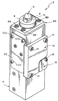
assembly 2 is shown in Fig. 1. Pin clamp assembly 2 illustratively comprises a
housing 4 with a locating pin 6 extending therefrom. Fingers 8 are configured
to
selectively extend and retract from locating pin 6. For example, when locating
pin 6
is retracted (as shown), fingers 8 are moved to the extended or clamped
position (also
as shown). Conversely, when locating pin 6 is extended upwardly, fingers 8 are
CA 02664555 2009-03-25
WO 2008/039760 PCT/US2007/079401
-6-
moved to the retracted or unclamped position. (See, e.g., Fig. 2a.)
Accordingly, pin
clamp assembly 2 has the ability to extend the locating pin 6 through a bore
in a
workpiece and then retract and use the fingers to hold the workpiece against
plate
surface 10. Also shown in this view is cover plate 12 illustratively attached
to
housing 4 via fasteners 14. This plate allows access to the interior of
housing 4
without having to disassemble the entire pin clamp assembly 2. A secondary
cover 16
is attached to cover plate 12 via fastener 18. This allows selective access to
the
interior of housing 4 as well. In one illustrative embodiment, the access is
to
manually unlock mechanism 20. (See e.g., Figs. 11a-c.) This illustrative
embodiment
also comprises fluid ports (not shown) wherein pneumatic pressure is supplied
to the
fluid ports to actuate locating pin 6. It is appreciated that in alternative
embodiments
other actuation sources may be employed. For example, electrical power, or
hydraulic fluid power, may be used in place of pneumatic power. Also shown in
Fig.
1 is access plate 22 attached to housing 4 via fasteners 100. Illustratively,
plate 22
provides access to internal components of the pin clamp assembly.
Alternatively,
plate 22 can be removed to allow other accessories to be attached and engage
those
internal components. (See, e.g., Figs. 14-17.) Also, plate 22 may attach to
cam
member 26. (See e.g., Fig. 5.)
Side-cross-sectional and detail views of pin clamp assembly 2 are
shown in Figs. 2a through c. Specifically, as shown in Fig. 2a, locating pin 6
is
shown extending from an opening 28 in housing 4. It is appreciated that in
this view
locating pin 6 is shown in an extended or typically unclamped position from
housing
4. A portion of locating pin 6 is positioned in cavity 30 within housing 4.
Fingers 8
shown in their retracted position are located adjacent the distal end of
locating pin 6.
Illustratively opposite fingers 8 is the attachment of piston rod 32 to
locating pin 6. In
one illustrative embodiment a pin 34 is disposed through a hole 36 in locating
pin 6
(see also Fig. 5a) and through an opening or slot 38 disposed in piston rod 32
to hold
the structures together. This piston rod 32 is connected to a pneumatic supply
assembly 40 that is located within bore 42 of housing 4. Bore 42 is capped at
the end
by cap assembly 44 which may further comprise any appropriate retaining rings
and/or seals. A piston 46 is attached to piston rod 32 illustratively via
fastener 48. It
CA 02664555 2009-03-25
WO 2008/039760 PCT/US2007/079401
-7-
is appreciated that the periphery of piston 46 may comprise any appropriate
seals to
prevent fluid transfer between opposed sections of bore 42. In this
illustrative
embodiment, piston rod 32 is disposed through bore 50 and extends into cavity
30. It
is appreciated from this view that collar 52 which lines bore 50 may serve as
a bearing
surface for piston rod 32, as well as seal 54 which separates cavity 30 from
bore 42.
As shown in this illustrated embodiment, as piston moves in direction 56,
piston rod
32 moves locating pin 6 in direction 56 as well. As piston 46 moves in
direction 58,
so too does locating pin 6. In one illustrative embodiment, to move locating
pin 6 in
direction 56 to an extended position, pin 34 engages end 60 of slot 38.
Conversely, to
move locating pin 6 in direction 58, piston 46 moves piston rod 32 and pin 34
engages
end 62. It is contemplated in an illustrative embodiment slot 38 is provided
to allow
some independent movement between piston rod 32 and locating pin 6.
Located within a cavity 64 disposed in locating pin 6 is a driving
member such as drive rod 66. Drive rod 66 illustratively comprises an angled
slot 84
that is configured to receive a driver 70. In an illustrative embodiment, a
portion of
driver 70 is located in slot 78 which is disposed in locating pin 6. Driver 70
comprises a cam follower 72 that engages slot 74 of cam member 26. Also shown
in
this view is illustrative wiper seal 77 located within cavity 30 between the
inner wall
of housing 4 and locating pin 6.
The detail views A and B of Figs. 2b and c, respectively, show an
illustrative relationship between the position of driver 70 and the ultimate
position of
fingers 8 located at the distal end of locating pin 6. In the illustrative
embodiment,
considering the extension of locating pin 6 to be the beginning of the stroke,
driver 70
is positioned illustratively to the far right side of slot 78 in direction 88.
This lateral
positioning of driver 70 may be dictated, at least in part, by the
configuration of cam
slot 74 of cam member 26. As shown in Fig. 2b, an illustrative jog 80 in cam
slot 74
moves cam follower 72 in direction 88 drawing driver 70 with it. Driver 70
also
illustratively comprises an angled portion that includes angled surfaces 82
that engage
a corresponding angled slot 84 disposed in drive rod 66. As can be seen from
the
figure, when driver 70 is moved laterally with respect to the rectilinear
movement of
locating pin 6, the angled surfaces 82 disposed in angled slot 84 move drive
rod 66
CA 02664555 2009-03-25
WO 2008/039760 PCT/US2007/079401
-8-
relative to locating pin 6. It is contemplated that in an illustrative
embodiment,
rectilinear movement of drive rod 66 can be independent of the movement of
locating
pin 6. The effect of this is that movement of drive rod 66 can move fingers 8
to
extended or retracted positions without interfering with the movement of
locating pin
6. The configuration of angled surfaces 82 of driver 70 causes drive pin 66 to
be
elevated which illustratively causes fingers 8 to be located in a retracted
position, as
shown in Fig. 2c.
Side-cross-sectional and detail views of pin clamp assembly 2 are
shown in Figs. 3a through c. Specifically regarding Fig. 3a, this view is
similar to that
shown in Fig. 2a except that piston 46 of pneumatic supply assembly 40 is
drawn
downward in direction 58. As this occurs, piston rod 32 draws locating pin 6
in
direction 58 as well, when pin 34 engages end 62 of slot 38. The resulting
movement
also moves driver 70 in direction 58. Consequently, cam follower 72 follows
cam slot
74 which moves driver 70 in direction 86. Because angled surfaces 82 of driver
70
and slot 84 of drive rod 66 angle upward relative to direction 86, drive rod
66 is
caused to move downward in direction 58. Because of the engagement between
drive
rod 66 and fingers 8, as drive rod 66 moves in direction 58, the fingers
extend
outwardly, illustratively in directions 86 and 88 to a clamping position. (See
also
Figs. 8a-c.) As shown in detail view C of Fig. 3b, cam follower 72 of driver
70
follows cam slot 74 and specifically moves passed jog 80 which displaces
driver 70
toward direction 86. Contrasting this view with detail A of Fig. 2b, it is
evident that
moving driver 70 farther in direction 86 within slot 78, allows drive rod 66
to move
farther down in direction 58 relative to driver 70. The effect of this
movement is
evident in detail D of Fig. 3c where fingers 8 become spread apart. A partial
view of
slot 90 disposed in fingers 8 is keyed to a key 92 (see Figs. 8a-c) which
causes the
fingers to spread in directions 86 and 88 as drive rod 66 is moved downward.
It is
appreciated that in other embodiments, the configuration of the key and slots
can be
modified so the fingers will move as desired in response to specific movement
of
drive rod 66.
Side-cross-sectional and detail views of pin clamp assembly 2 are
shown in Figs. 4a-c. These views are similar to that of Figs. 2 and 3 with the
CA 02664555 2009-03-25
WO 2008/039760 PCT/US2007/079401
-9-
exception of locating pin 6 moved to the retracted position in direction 58,
and the
resulting jog of cam follower 72 in slot 74. For example, as shown in Fig. 4a,
piston
46 moves locating pin 6 further in direction 58. As was the case in Fig. 3,
fingers 8
shown in this view are extended and available to engage a workpiece against
plate
surface 10, for example. Also shown in this view is piston rod 32 engaging end
62 of
slot 38 to draw locating pin 6 downward in direction 58. It is contemplated
that
continued force against piston 46 can maintain locating pin 6 and fingers 8 in
the
position shown. Specifically regarding detail E of Fig. 4b, cam follower 72 is
shown
to be illustratively moved to its fullest extent within cam slot 74 in
direction 58. This
maintains the relative downward positioning of drive rod 66 relative to driver
70
which maintains the extension of fingers 8 to the clamp position as shown in
detail F
of Fig. 4c. It is appreciated that the progression shown in Figs. 2-4
constitutes a
stroke of the pin clamp assembly 2. It is contemplated that movement of piston
46 in
the opposite direction, direction 56, the structures described herein will
move in
essentially opposite fashion to extend locating pin 6 upward, which moves
driver 70
upward so cam follower 72 traverses jog 80 in cam slot 74. The angled surfaces
82
and slot 84 will draw drive rod 66 upward in direction 56 (while moving driver
70 in
direction 88), which based on its engagement with fingers 8 will retract the
same to an
unclamped position as originally shown in Fig. 2a.
Perspective-exploded and detail views of illustrative pin clamp
assembly 2 are shown in Figs. 5a-c. As shown in Fig. 5a, housing 4 is
configured to
receive locating pin 6 and drive rod 66 within cavity 30. A longitudinal axis
94 is
shown disposed through locating pin 6 and drive rod 66. As previously
discussed,
drive rod 66 is configured to be inserted into locating pin 6. Plate surface
10 is shown
to be part of sleeve 96 that is attached to housing 4 via fasteners 98. It is
contemplated that longitudinal axis 94 illustratively extends through opening
28
disposed in sleeve 96. Also shown in this view is slot 78 disposed through
locating
pin 6 and configured to receive driver 70, and slot 84 disposed in drive rod
66
receives the angled surfaces 82 of driver 70. Also shown in this view is
driver 70
with cam follower 72 extending therefrom and configured to be located within
cavity
30 of housing 4. It is also appreciated how cam member 26 along with access
plate
CA 02664555 2009-03-25
WO 2008/039760 PCT/US2007/079401
-10-
22 can be attached to housing 4 via fasteners 100. It is contemplated that in
additional
embodiments, access plate 22 and/or cam member 26 can be selectively replaced
with
an alternative accessory. For example, also shown in this view is strip-off
cylinder
assembly 102. (See also Figs. 15-17.) As further discussed herein, strip-off
cylinder
assembly 102 can move the fingers as desired while locating pin 6 is moved to
either
its extended or retracted position relative to housing 4. What is shown in
Fig. 5a
specifically, is an illustrative piston 104 located within a cavity 106 of
strip-off
housing 108. Piston 104 is configured to move rectilinearly within housing
108.
Various seals 110 border the periphery of piston 104. Caps 112 along with
retaining
rings 114 and seals 116 caps cavity 106 of housing 108. A modified access
plate 118
and cam member 120 can be located on housing 4 similar to that described with
regard to access plate 22 and cam member 26. Illustratively a pin 122 is
configured to
be disposed within an opening 124 of access plate 118 to allow engagement of
pin
122 within cavity 30 of housing 4, as described and illustratively
characterized further
herein. Fasteners 126 attach housing 108 along with access plate 118 and cam
member 120 onto housing 4 similar to that previously discussed with regard to
access
plate 22 and cam member 26.
The detail views G and H of Figs. 5b and c show an illustrative
configuration of drive rod 66 and fingers 8. In this illustrative embodiment,
as shown
in detail G of Fig. 5b, the distal end of drive rod 66 illustratively
comprises a tang 128
that has an illustrative angled key 92 extending therefrom. Finger 8, as shown
in
detail H of Fig. 5c, has an angled slot 90 disposed therein configured to
receive
angled key 92. It is appreciated that both sides of tang 128 may have such an
angled
key 92 and, furthermore, the keys may be configured to be angled in opposed
directions (see also Fig. 8a). It is appreciated from this and other views
that keys 92
are angled with respect to longitudinal axis 94, so that as drive rod 66 moves
rectilinearly along longitudinal axis 94, keys 92 can move the fingers 8
laterally with
respect to that longitudinal axis. It can be further appreciated that
providing structures
at such an angle with respect to a particular axis can be used to translate
movement
laterally to that axis. In other words, such angled bodies can facilitate
movement in
both X and Y directions. (See, Fig. 8.)
CA 02664555 2009-03-25
WO 2008/039760 PCT/US2007/079401
-11-
End and side-cross-sectional views of pin clamp assembly 2 are shown
in Figs. 6a-c. The section views of Figs. 6b and c of pin clamp assembly 2
were taken
along lines A-A and B-B, respectively, as shown in the end view of clamp
assembly 2
in Fig. 6a. The sectional view shown in Fig. 6b is similar to that shown in
Figs. 2-4
except that here, end 60 of slot 38 engages pin 34. This is illustratively the
effect of
piston 46 moving locating pin 6 upward in direction 56 to extend locating pin
6. The
sectional view of Fig. 6c is a reverse-angled detail view of locating pin 6
that includes
driver 70 and shows the interaction between cam follower 72 and cam slot 74.
Side-elevational and cross-sectional views of an illustrative
embodiment of locating pin 6 is shown in Figs. 7a and b. The cross-sectional
view
shown in Fig. 7b is taken along lines C-C of Fig. 7a. Illustratively, locating
pin 6
comprises a recess 130 that is configured to receive tang 128 of drive rod 66,
as well
as fingers 8. This recess leads into cavity 30 disposed within locating pin 6
which
receives drive rod 66. Slot 78 is shown disposed through locating pin 6
traversing
cavity 30 and extending out the periphery of locating pin 6 at opposed ends.
Slot 78
also illustratively varies at each end of locating pin 6. This configuration
is
illustrative to accommodate the configuration of driver 70. It is appreciated,
however,
that the configuration of slot 78 can vary to accommodate a driver of
alternate
configuration. Also shown in this view is bore 36 that receives pin 34 and
bore 132
that is configured to receive a fastener for an illustrative spring holder
that is used on
the locking mechanism 20 discussed further herein. (See also Fig. 11.)
End and side-elevational, perspective-exploded and side and top views
of illustrative embodiments of drive rod 60 and finger 8 are shown in Figs. 8a-
c. The
views of drive rod 66 in Fig. 8a show the angle of slot 84 relative to the
longitudinal
axis 94. Similarly, angled keys 92 are located on each side of tang 128 as
well. Also
shown in this view is how keys 92 on each side of tang 128 are angularly
oriented in
opposite directions. For this illustrative embodiment, the two fingers 8 are
configured
to extend outwardly from locating pin 6 to assist clamping a workpiece. For
example,
as shown herein, drive rod 66 is moveable along the Y, -Y axis. Such angled
keys 92
can typically provide a path in both X and Y directions. Here, one key 92
provides a
path in the X, Y direction and the opposite key 92 provides a path in the Y, -
X
CA 02664555 2009-03-25
WO 2008/039760 PCT/US2007/079401
-12-
direction. Fingers 8, however, are confined from moving in the Y, -Y axis by
the
proximal end of locating pin 6. (See also Fig. 7.) Consequently, fingers 8
illustratively only move in either the X or -X direction, as shown in Figs. 2-
4. It can
be appreciated, however, that alternate embodiments of the key can move the
fingers
in other directions.
The perspective-exploded view of drive rod 66 and finger 8 and Fig.
8b, depicts how the two structures will mate. In this case, slot 90 is
engagable with
key 92 on one side of tang 128. It is appreciated that the second finger 8 has
a similar
slot that engages key 92 on the other side of tang 128. Additional views of
finger 8
are shown in Fig. 8c. It is appreciated that in other embodiments, finger or
fingers 8
can be modified to move in a direction as desired, resulting from the
rectilinear
movement of drive rod 66.
Side and end views of an illustrative embodiment of driver 70, along
with an isolated detail view of driver 70 with locating pin 6, cam 26, and
access plate
22 are shown in Figs. 9a-c. The view of driver 70 in Fig. 9a shows an
illustrative
configuration that includes angled surfaces 82 that are configured to be
received in
slot 84 of drive rod 66. The end view of driver 70 shown in Fig. 9b also shows
a
profile view of cam follower 72. It is appreciated that alternative
embodiments of
driver 70 may include a cam follower of different configuration to follow a
cam slot.
And Fig. 9c shows an isolated side view of driver 70 and its associated
structures
including locating pin 6 and cam member 26.
Exploded, perspective, and cross-sectional detailed views of an
illustrative shim and sleeve assembly 140 are shown in Figs. lOa-c,
respectively. As
shown in the exploded view of Fig. 10a, shim and sleeve assembly 140 comprises
a
sleeve 96 that is fastened to the top of housing 4 via fasteners 98 disposed
through
bores 142 and 144 of sleeve 96 and housing 4 respectively. In one illustrative
embodiment, shims 138 include bores 146 disposed therethrough that also
receive
fasteners 98. Shims 138 can, thus, be sandwiched and secured between sleeve 96
and
housing 4. It is appreciated, however, that the thickness of shims 138 can be
any
amount that is useful to provide a desirable amount of shrouding about
locating pin 6.
CA 02664555 2009-03-25
WO 2008/039760 PCT/US2007/079401
- 13-
The perspective view of shim and sleeve assembly 140 is shown in Fig. 10b.
This
view shows how locating pin 6 extends from opening 28 of sleeve 96. The cross-
sectional view of Fig. 1Oc further illustrates the utility of shims 138. As
shown
herein, shims 138 allow sleeve 96 to be adjusted upward or downward along
locating
pin 6. The use of such shims 138 means that the top surface of sleeve 96 may
not
require machining to obtain a desired amount of shrouding about locating pin
6.
Side and detail views of locking/unlocking mechanism 20 of pin clamp
2 are shown in Figs. 11 a-c. As shown in Figs. 11 a and b, cavity 30 is formed
in
housing 4. Cavity 30 provides access to locating pin 6, as well as piston rod
32. In
one illustrative embodiment, mechanism 20 is configured to be a locking
mechanism.
This can be particularly useful during loss of fluid power to clamp 2.
Illustratively,
when locating pin 6 is moved in the downward direction 58, the location of pin
208
with respect to the locating pin 6 is caused to be wedged between surfaces 232
and
234 by the bias created from spring 236. This wedging between the two surfaces
prevents locating pin 6 from moving upwardly in direction 56. To unlock
mechanism
20, as shown in Fig. I lc, lock release 206 or other structure or mechanism
can push
pin 208 upward unwedging pin 208 from between surfaces 234 and 232. The force
of
this upward movement should be greater than the downward bias of spring 236 to
cause pin 208 to position itself in a nonwedging position between surfaces 234
and
232. The illustrative shape of cam surface 234 is such that in the lower
position, that
surface serves as a wedging surface, whereas farther upward thereon, it no
longer
possesses such wedging properties. Mechanism 20 can also be configured to
manually move locating pin 6 upward in direction 56 to retract fingers 8 and
allow
release of any held workpiece. For example, when power is restored to clamp 2,
the
force of that power is sufficient to overcome the wedging force created by pin
208
and surfaces 232, 234. This is illustratively accomplished by the lock release
206
attached to piston rod 32 as shown in Fig. 5c. In this illustrative
embodiment, slot 38
and piston rod 32 (see Fig. 2a) allow movement of piston rod 30 to some extent
before it engages and moves locating pin 6. In this embodiment that extent of
travel
is enough to allow head 238 of lock release 206 to engage pin 208. Using the
force of
the traveling piston rod 30, pin 208 is pushed out of the way, thus, unwedging
it from
CA 02664555 2009-03-25
WO 2008/039760 PCT/US2007/079401
-14-
between surfaces 132 and 134 prior to piston rod 30's engagement and movement
of
locating pin 6. Once pin 208 is unwedged, locating pin 6 will be free to move
upwardly in direction 56.
Side and detail-cross-sectional views of pin clamp assembly 2 are
shown in Figs. 12a and b. The section view shown in Fig. 12b was taken along
lines
F-F of Fig. 12a. In this illustrative embodiment, a location sensing flag 150
can be
employed. Also in this illustrative embodiment, a standard bore plug at the
end of the
pin clamp assembly 2 can be replaced by a flag bore plug 152. A secondary
piston
rod 154 can then be attached to piston 46 and, illustratively, pass
therethrough to
thread or otherwise attach to piston rod 32. Plug 152 may illustratively
comprise a
rod wiper/seal 156, as well as a rod bearing 158 that receives secondary
piston rod
154. A flag 160 is mounted to secondary piston rod 154, illustratively
external of
clamp body 4 and secured to rod 154 via spring pin 162. Flag 160 can be used
as a
target for a laser, optical, or other sensor, which detects when the clamp is
in an
extended or retracted position. It is appreciated that the configuration of
assembly
150 shown is illustrative. It is contemplated that in alternate embodiments
the flag
can be of a shape or configuration useful for assisting and detecting the
position of
structures of pin clamp assembly 2.
Top, side-cross-sectional, and detail views of clamp assembly 2
disclosing an illustrative embodiment of a detent assembly 170 is shown in
Figs. 13a-
c. The cross-sectional view of pin clamp assembly 2 shown in Fig. 13b is taken
along
lines G-G of Fig. 13a, and the detail view of Fig. 13c is taken from detail I
of the
cross-sectional view of Fig. 13b. Detent assembly 170 can be used to prevent
locating
pin 6 from moving until some force of specified value causes it to be freed
from the
detent assembly. In this illustrative embodiment, a detent 172, such as a ball
detent or
other custom or commercially available detent can be located within a bore 174
disposed in housing 4. Bore 174 is in communication with a slot or other
cavity 176.
Ball detent 172 is engagable with driver 70 having a portion of the same
located in
slot 176. In an illustrative embodiment detent 172 engages a detent slot 178
or other
similar formation in driver 70. Detent 172 is biased against driver 70 and is
configured to engage slot 178 when driver 70 is located at a particular
location along
CA 02664555 2009-03-25
WO 2008/039760 PCT/US2007/079401
-15-
the stroke of locating pin 6. In one illustrative embodiment, such a location
is where
locating pin 6 is at full extension, as shown in Fig. 13b. It is appreciated,
however,
that such a slot 178 can be located anywhere along the stroke of locating pin
6. When
detent 172 engages cavity 178, locating pin 6 is effectively locked into
place. A force
such as the fluid pressure acting on piston 46 may be used to overcome the
bias force
175 from detent 172 against slot 178 to overcome the same and allow driver 70
and,
thus, locating pin 6 to unlock.
Front elevational and side-cross-sectional views of another illustrative
embodiment of pin clamp assembly 2 are shown in Figs. 14a and b. The cross-
sectional view of pin clamp assembly 2 shown in Fig. 14 is taken along lines D-
D of
Fig. 14a. This illustrative embodiment includes strip-off cylinder assembly
102. In
this illustrative embodiment, strip-off cylinder assembly 102 can move fingers
8 when
locating pin 6 is located in either extended or retracted positions.
Illustratively, as
port 182 of strip-off cylinder housing 108 is pressurized, pin 122, coupled to
cylinder
piston 104, causes the cam member 120 to move upward in direction 56. This
causes
driver 70 to move, illustratively, in direction 88 in clamp housing 4. As this
occurs,
drive pin 66 is forced downward in direction 58 by means previously discussed.
This
motion causes fingers 8 to move out of locating pin 6, even when it is in the
extended
position. Conversely, when port 184 of strip-off cylinder housing 108 assembly
is
pressurized, cam member 120 is moved downward in direction 58. This causes
driver
70 to move, illustratively, in direction 86. This causes drive pin 66 to move
upward
in direction 56 inside locating pin 6 which causes fingers 8 to retract, even
if locating
pin 6 is already in the retracted position. It is appreciated that the strip-
off cylinder
assembly 102 may cause movement of the fingers independent of movement of
locating pin 6. For example, locating pin 6 may even be stationary during the
movement of driver 70 when strip-off cylinder assembly 102 is activated. This
allows
control over extension or retraction of fingers 8 independent of the movement
of
locating pin 6. This can be useful in instances where sheet metal or other
workpieces
get bound-up or otherwise stuck on locating pin 6. It is further appreciated
that cam
follower 72 or driver 70 operates in cam path 186 similar to cam slot 74 in
previous
embodiments. (See, e.g., Fig. 2a.)
CA 02664555 2009-03-25
WO 2008/039760 PCT/US2007/079401
-16-
Cross-sectional progression views of pin clamp assembly 2 with strip-
off cylinder assembly 102 attached thereto is shown in Figs. 15-17. These
cross-
sectional views of pin clamp assembly 2 are similar to those views shown in
Figs. 2-4,
but at reverse angle. As shown in Figs. 15a-c, during normal operation, as
locating
pin 6 retracts, actuation of piston 46 moves the same in direction 58. Fingers
8 extend
as previously discussed with respect to Figs. 2-4. The strip-off cylinder
assembly 102
does not interfere with this operation. This is because the position of
assembly 102
causes jog 188 located in cam slot 186 to be at about the same position as jog
80 is in
cam slot 74 of the previous embodiments. In contrast, as shown in the
progression
view of Figs. 16a-c, when piston 104 is moved in direction 56, cam member 120
is
also moved in the same direction. This has the effect of moving jog 188 upward
in
direction 56 as well. This has the further effect of keeping driver 70 moved
over in
direction 88 during the entire stroke of locating pin 6. As this view shows,
as piston
46 moves downward in direction 58, cam follower 72 has no opportunity to
traverse
jog 188 and move driver 70, and, thus, move drive rod 66 upward to retract
fingers 8.
Consequently, fingers 8 remain in the extended position for the length of the
stroke.
Conversely, as shown in the progression view of Fig. 17a-c, when piston 104 is
moved downward in direction 58, as shown therein, so too does cam member 120.
This has the opposite effect as that described with respect to Figs. 16a-c.
Particularly,
cam follower 72 of driver 70 is maintained in the upper portion of cam slot
186
throughout the entire stroke of locating pin 6. The position of cam slot 186
does not
allow cam follower 72 to traverse jog 188. Therefore, driver 70 is maintained
toward
direction 86 which maintains drive rod 66 in an upward position preventing
fingers 8
from extending outward, regardless of the movement of either locating pin 6 or
piston
46. This allows locating pin 6 to move as desired without having the fingers
extend
as well. It is appreciated that in an illustrative embodiment, access panel
118 is fixed
to cam member 120 and moves therewith upon movement of pin 122 by piston 104.
Side views of another embodiment of a pin clamp assembly 300, along
with complimentary detail views, are shown in Figs. 18a-d. The view of pin
clamp
assembly shown in Fig. 18a shows locating pin 6 moved in an illustrative full
extension. This is typical of the pin clamp assembly according to the previous
CA 02664555 2009-03-25
WO 2008/039760 PCT/US2007/079401
-17-
embodiments. However, the present embodiment includes split fingers 302. An
illustrative purpose of these fingers is to assist centering a workpiece on
the pin clamp
and then clamping down on the workpiece. In an illustrative embodiment, split
fingers 302 comprise a centering portion 304 and a clamping portion 306. As
shown
in the progression views of 18b-d, once locating pin is extended through a
hole or
cavity in the workpiece, centering portion 304 ensures the workpiece is
centered on
locating pin 6 and then clamped to hold into place. For example, as shown in
Fig.
18b, locating pin 6 is extended through bore 308 of a workpiece 310, as shown
in this
view fingers 302 are in a retracted position. A clearly evident effect of this
configuration is that the pin clamp does not need to extend so far upward in
direction
56. (Compare Fig. 18b with Fig. 18a.) Illustratively, the centering portion
304 of
split fingers 302 face wall surface 312 of bore 308. Once locating pin 6 is in
this
position, fingers 302 can move outward in directions 314 and 316. The
centering
portions 304 engage wall 312. This ensures centering of bore 308
illustratively with
respect to locating pin 6. As shown in Fig. 18d, when locating pin 6 retracts
further in
direction 58, the clamping portions 306 which are shown to extend radially
farther
than centering portions 304, clamp down on workpiece 310.
Several views of drive rod 320 and split fingers 302 are shown in Figs.
19a-c. It is appreciated that drive rod 320 can be the same as drive rod 66
disclosed in
the previous embodiments. Drive rod 320 may comprise a slot 322 similar to
that of
slot 84 and may have keys 324 similar to keys 92 of drive rod 66. (Compare
with Fig.
8a and b.) These views, particularly in Fig. 19c, show the illustrative
configuration of
split finger 302. This illustrative embodiment shows finger 302 being similar
to
fingers 8 disclosed in previous embodiments, particularly slot 326 which is
similar to
slot 90 in the previous embodiments. It is appreciated, however, that the
configuration of split fingers 302 can vary including separate components or
structures for the centering and clamping portions.
Front and side-cross-sectional views of pin clamp assembly 300 are
shown in Figs. 20a and b. The cross-sectional view shown in Fig. 20b is taken
from
lines G-G of Fig. 20a. In one illustrative embodiment, the movement of
locating pin 6
can be adjusted by means of strip-off assembly 102, as described in previous
CA 02664555 2009-03-25
WO 2008/039760 PCT/US2007/079401
-18-
embodiments. The strip-off assembly 102 can also be used to manipulate the
movement of fingers 302 similar to that described with respect to fingers 8 in
previous
embodiments. It is appreciated that other mechanisms can be used to limit the
stroke
of locating pin 6, if so desired. An example of such is a reducer 330 shown
herein
that is located adjacent piston 46. As evident from the drawing, reducer 330
effectively limits the stroke or distance of travel available to piston rod 32
and
ultimately locating pin 6. Other examples to reduce the stroke of locating pin
6 is
possibly use a shorter piston rod in the clamp, or change the configuration of
the
body, or the bores within the body.
An exploded view of pin clamp assembly 400 is shown in Fig. 21.
This assembly includes a housing 402, a locating pin 404, and a body 406. A
lock
assembly 410 is also shown. In this illustrative embodiment, lock assembly 410
comprises a hook mount 412 that attaches to body 406 via fasteners 414. A step
416
is illustratively formed on body 406 which forms a lip support 417. This
illustrative
mount configuration may assist removing shear loads from fasteners 414 that
attach
hook mount 412 to body 406. A hook 418 is mounted to hook mount 412
illustratively via dowels 420, thereby allowing hook 418 to pivot with respect
to
mount 412. Illustratively a compression spring 422 may be, employed to bias
hook
418 outward from mount 412 and allow hook 418 to engage catch 424. In an
illustrative embodiment, catch 424 is configured to slide up and down in
directions
446 and 448 along housing 402 to accommodate clamped material of different
thicknesses. An adjustment plate 426, having slots 428 and 430, is mounted in
a
pocket 432 via fasteners 434, as illustratively shown. Adjustment plate 426 is
configured to slide laterally in directions 442 and 444 within pocket 432 by
simply
loosening fasteners 434. Catch 424 comprises a dowel 436 that extends
therefrom
and is disposed through slot 440 of housing 402, as well as angled slot 428 of
adjustment plate 426. Lateral movement of adjustment plate 426 in directions
442
and 444 raise and lower catch 424 with respect to hook 418. This allows the
assembly to accommodate clamped material of various thicknesses.
Illustratively,
engagement between slot 428 and dowel 436 may result in relatively precise
movement of catch 424. This may translate into a more precise adjustment of
catch
CA 02664555 2009-03-25
WO 2008/039760 PCT/US2007/079401
-19-
424 up and down in either direction 446 or 448. The engagement between dowel
436
and slot 428 may also transfer shear loads from catch 424 to housing 402 and
plate
426.
An unlock bracket 450 illustratively comprising angled surfaces 452 is
configured to engage hook 418 at pins 454. This engagement causes hook 418 to
pivot on pins 420 and unlatch from catch 424. As previously described, piston
rod
458 may be configured to move prior to movement of body 406. This means that
unlock bracket 450, which may be coupled to piston rod 458, can move upward in
direction 446, engage pins 454, and unlatch hook 418 from catch 424, before
body
406 piston rod begins moving. It is appreciated that the contour of the hook
and catch
are configured to maintain a hold under loss of actuation force or if locating
pin 404 is
being pulled on. It is further appreciated that the contours and/or shapes of
the hook
and latch may be modified from that shown in this illustrative embodiment.
The progression views in Figs. 22a-f show how lock assembly 410
works to lock locating pin 404. As shown in Fig. 22a, locating pin 404 is
extended
upward in direction 446 at its uppermost extent. Hook 418 is biased against
angled
surface 456 of catch 424 via compression spring 422, as shown in Fig. 22b. As
locating pin 404 descends in direction 448, as shown in Fig. 22c, hook 418
continues
to ride along sloped surface 456. The view in Fig. 22d shows piston rod 458
continuing to descend in direction 448 as well. When locating pin 404 is moved
to its
lower most extent and clamps onto a workpiece 460, hook 418 couples or latches
with
catch 424 to hold locating pin 404 in place as shown in Fig. 22f. It can be
appreciated
from this view that if locating pin 404 was attempted to be moved by an
external
source upward in direction 446, lock assembly 410 would prevent that movement
from happening.
The progression views shown in Figs. 23a-f demonstrate how lock
assembly 410 is released to allow locating pin 404 to extend upward in
direction 446.
As shown in Figs. 23a and b, with locating pin 404 clamped down against
workpiece
460, piston rod 458 still moves upward in direction 446. It is notable that in
this
illustrative embodiment, locating pin 404 is not moved during the initial
movement of
CA 02664555 2009-03-25
WO 2008/039760 PCT/US2007/079401
-20-
piston rod 458. Design for this feature has been described in previous
embodiments.
Here, movement of piston rod 458 causes movement of unlock bracket 450 as
well.
As shown in Figs. 23c and d, locating pin 404 still does not release workpiece
460,
yet surfaces 452 of unlock bracket 450 engage pin 454 of hook 418. Surfaces
452 are
angled so that the upward movement of unlock bracket 450 draws hook assembly
418
inward in direction 464 against the bias of compression spring 422. The
configuration
of hook 418 and catch 424 causes hook 418 to begin unlatching by pivoting
about
dowels 420. The continued movement of piston rod 458 upward in direction 446
continues to cause unlock bracket 450 to unlatch from hook 418 and catch 424,
as
shown in Fig. 23f. At this position, locating pin 404 has still not released
workpiece
460 as shown in Fig. 23e. Nevertheless, hook 418 has cleared catch 424 which
allows
locating pin 404 to freely move upward in direction 446 via piston rod 458, to
release
workpiece 460.
Although the present disclosure has been described with reference to
particular means, materials and embodiments, from the foregoing description,
one
skilled in the art can easily ascertain the essential characteristics of the
present
disclosure and various changes and modifications may be made to adapt the
various
uses and characteristics without departing from the spirit and scope of the
present
invention as set forth in the following claims.