Note: Descriptions are shown in the official language in which they were submitted.
CA 02664640 2009-03-26
WO 2008/039850 PCT/US2007/079557
PATENT APPLICATION
TITLE: INTERVERTEBRAL PROSTHESIS ENDPLATE HAVING DOUBLE
DOME AND SURGICAL TOOLS FOR IMPLANTING SAME
CROSS REFERENCE TO RELATED APLICATION
[0001] This application claims the benefit of U.S.
Provisional Application No. 60/847,103, filed September 26,
2006, the entire disclosure of which is incorporated herein
by reference, and the benefit of U.S. Provisional
Application No. 60/847,359, filed September 27, 2006, the
entire disclosure of which is incorporated herein by
reference.
BACKGROUND OF THE INVENTION
Field of the Invention
[0002] This invention relates to prostheses for
replacing a human intervertebral disc and instruments for
implanting such a prosthesis, and more particularly to an
endplate for such a prosthesis having a domed surface for
contacting an adjacent vertebra in a human spinal motion
segment.
- 1 -
CA 02664640 2009-03-26
WO 2008/039850 PCT/US2007/079557
Background Art
[0003] The human spinal column achieves its remarkable
combination of strong support and appropriate flexibility
by reason of its structure comprising bony vertebrae
separated by intervertebral discs of softer and flexible
tissue that allow limited motion between adjacent vertebrae
in flexion-extension, lateral bending, and torsion. Each
individual flexible element of the spine, comprising a pair
of adjacent vertebrae separated by an intervertebral disc,
constitutes a spinal motion segment. The proper function
of such a spinal motion segment requires the intervertebral
disc to provide proper separation between the vertebrae
while allowing sufficient relative motion in the median,
coronal and transverse anatomical planes of the body.
While each intervertebral disc typically performs its
function effectively without conscious awareness, the disc
and surrounding tissues are provided with ample innervation
that informs the individual of any damage and/or
malfunction by providing a pain signal.
The spinal regions most susceptible to painful
pathology of the intervertebral disc are the cervical and
lumbar regions. Such painful pathology is typically the
result of some traumatic injury or age-related changes in
the structure and function of the intervertebral disc.
- 2 -
CA 02664640 2009-03-26
WO 2008/039850 PCT/US2007/079557
The most common pathologic condition causing chronic
low back pain and neck pain is degenerative disc
disease (DDD), which is typically the result of age-related
changes in the tissues constituting the intervertebral
disc, with accompanying abnormalities, e.g., deformation,
in the functional structures of the disc. Under such
conditions, even normal movement between the adjacent
vertebrae can cause pain, which may become chronic and
sufficiently severe to result in significant disability.
When non-invasive treatment fails to relieve chronic
disabling back pain caused by such disease, recourse is had
to surgical intervention. For some time, palliative
surgical procedures such as disc excision, decompression,
and/or spinal fusion have been performed to relieve
intractable pain of patients with degenerative disc
disease. More recently, artificial intervertebral disc
prostheses have been developed, which have made it possible
to replace a degenerated disc with such a prosthesis to
achieve pain relief and restore anatomical function.
[0004] A number of factors must be considered in the
design of an intervertebral disc prosthesis if a successful
outcome of disc arthroplasty is to be expected. The
prosthesis design must provide for proper positioning,
correct alignment, congruent contact surface area, and
- 3 -
CA 02664640 2009-03-26
WO 2008/039850 PCT/US2007/079557
immediate post-operative prosthetic stability within the
disc space. In particular, the conformation of the
vertebra-contacting surface of the prosthesis at the
vertebra-prosthesis interface is of significant importance,
particularly for post-operative stability of the prosthesis
in the intervertebral space. Experience has shown that the
clinical results of intervertebral disc arthroplasty are
closely correlated to the proper initial positioning of the
disc prosthesis in the disc space and subsequent
maintenance thereof. For instance, if an implanted disc
prosthesis does not maintain a stable position within the
intervertebral space, the patient may experience post-
operative accelerated disc degeneration in adjacent spinal
motion segments, as well as formation of osteophytic
growths on the vertebrae.
[0005] Another possible post-operative complication is
subsidence of the disc prosthesis into an adjacent
vertebra. Such instability is related to at least three
factors: contact area between the prosthesis and the
adjacent vertebral body, bone mineral density in the
contacting surface of the vertebral body, and applied load.
In particular, the effective prosthesis-vertebra contact
area is affected by the variable curvature and irregular
surface profile of the adjacent vertebra, both of which
- 4 -
CA 02664640 2009-03-26
WO 2008/039850 PCT/US2007/079557
vary significantly from patient to patient, e.g., in the
lumbosacral spine which is the site of many intervertebral
disc arthroplasties.
[0006] The great variety of designs that have been
proposed for the bone-contacting surface of intervertebral
disc prostheses can be taken as evidence that an ideal
design has yet to be achieved. Examples of such prostheses
have included those with relatively flat vertebra-
contacting surfaces, those with domed profiles, or those
incorporating other specially configured shapes such as
corrugated or serrated surfaces or protruded platforms.
[0007] Besides the general shape of the bone contacting
surface, known intervertebral disc prostheses have
incorporated additional structures to enhance the security
of fixation to the vertebral bone. Some designs have
incorporated provisions for fixation using screws driven
either into the anterior or lateral sides of the adjacent
vertebrae or into the vertebral endplate itself. The bone-
contacting surfaces of other prostheses have been provided
with spikes, keels, serrations, or the like, in order to
provide stable fixation of the prosthesis.
[0008] However, certain drawbacks have been observed
with the previously known intervertebral disc prostheses.
For example, flat prosthetic endplate designs present
- 5 -
CA 02664640 2009-03-26
WO 2008/039850 PCT/US2007/079557
problems of incongruous fit between the prosthetic endplate
and the concave end surface of the vertebral body. Such a
mismatch between the shapes can result in post-operative
instability of the prosthesis in the disc space, in
particular, settling of the prosthesis into the adjacent
vertebra (subsidence). Designs that attempt to compensate
for this mismatch by providing additional structures such
as keel, spikes, and the like incur problems due to the
greater distraction between vertebrae required for their
implantation. Designs that employ screws placed into the
endplates of the vertebrae encounter difficulties in
implantation because of the limited working space and the
relatively thin bone structures of the vertebral endplates,
which do not provide a strong substrate for screw fixation.
Some intervertebral prostheses have incorporated
endplates having dome-shaped surfaces for contact with the
adjacent vertebral bodies. Both spherical domes and
ellipsoidal domes have been employed. Ellipsoidal domes
better approximate the planform of a vertebral body, and,
when seated in a corresponding ellipsoidal seat reamed in
the endplate of the vertebral body, provide a measure of
torsional stability. However, preparation of such an
ellipsoidal seat and proper alignment with the vertebrae
can present some surgical difficulties. Spherical domes,
- 6 -
CA 02664640 2009-03-26
WO 2008/039850 PCT/US2007/079557
having a circular planform, are more easily fitted to a
prepared seat, but, by themselves, tend to provide less
torsional stability.
Accordingly, a need has continued to exist for an
endplate design that can alleviate the problems experienced
in implantation of known intervertebral disc prostheses.
SUNlNlARY OF THE INVENTION
According to the invention an endplate for an
intervertebral disc prosthesis is provided that promotes a
stable relationship between the prosthesis and the adjacent
vertebrae after implantation. The invention also
encompasses tools for preparing a seat or recess in a
vertebral body to provide a congruent fit for the endplate
of the invention, as well as a surgical procedure for
preparing a surgical site and implanting a prosthesis using
an endplate of the invention.
The prosthesis endplate of the invention comprises:
a generally planar base plate having a periphery sized
and configured to fit within an intervertebral space of a
human spinal motion segment;
a first elevated region, or dome, within the base
plate periphery, and
- 7 -
CA 02664640 2009-03-26
WO 2008/039850 PCT/US2007/079557
a second elevated region, or dome, within the boundary
of the first elevated region.
The antero-posterior and side-to-side (medial-lateral)
dimensions of the first elevated region are made to be
unequal in order to provide resistance to torsional
movement between the prosthesis endplate and the adjacent
vertebral body under the normal stresses produced by the
physiological motion of the spinal motion segment.
Furthermore, the laterally opposite sidewalls of the first
elevated region are defined by arcs that terminate in
sagittal planes of the endplate, and are symmetrical with
respect to a coronal plane of the endplate. In an
alternate embodiment, the arcs terminating the lateral side
portions of the first elevated region are circular arcs
centered in sagittal planes of the endplate, and may or may
not be symmetrical with respect to a coronal plane of the
endplate.
The second elevated region is generally dome-shaped,
and the laterally opposite side portions are defined by
circular arcs having a common center located in the median
plane of the endplate.
A bone rasp apparatus for forming a recess or seat in
a vertebral body for receiving a prosthesis endplate
according to the invention includes at least one bone rasp
- 8 -
CA 02664640 2009-03-26
WO 2008/039850 PCT/US2007/079557
tool that includes a rasp head and a handle for
manipulating the head within an intervertebral space. The
rasp head includes a pivot member that can be inserted into
a recess formed in the vertebral body endplate rasp teeth
arranged on the rasp head to prepare at least a portion of
a recess or seat for a vertebral endplate when the rasp
head is reciprocally rotated about the pivot member.
A groove-cutter for preparing an antero-posterior
groove in a vertebral body to receive a fin or keel of an
intervertebral disk prosthesis endplate includes a cutter
guide member having a handle and a guide head sized and
configured to be seated in a recess or seat previously
formed in a vertebral body. The groove-cutter is provided
with an antero-posterior guide slot that guides the antero-
posterior reciprocating cutter and a stowage recess for
stowing the cutter in a protected position while the guide
head is inserted into the intervertebral space. The cutter
is mounted on a reciprocable and rotatable shaft that
actuates the cutter by an antero-posterior reciprocating
motion and can be rotated to place the cutter in the
stowage recess.
Accordingly, one feature of the invention is an
endplate for an intervertebral disc prosthesis that has a
dome configuration which provides for improved stability
- 9 -
CA 02664640 2009-03-26
WO 2008/039850 PCT/US2007/079557
under imposed stresses that tend to produce torsional
instability and/or extrusion of the prosthesis from the
intervertebral space.
A further feature of the invention is an endplate for
an intervertebral disc prosthesis that will facilitate
reliable and easy positioning, alignment, preparation of a
congruent contact surface, and better stabilization against
axial, bending, torsion and translation in the lumbar,
lumbosacral or cervical spine.
A further feature of the invention is the formation of
a concavity in the vertebral endplate to provide a
congruent fit between a domed surface of a prosthesis
endplate and the bony vertebral endplate.
A further feature of the invention is a procedure and
instrumentation for preparing a generally concave seat in a
vertebral endplate to receive an intervertebral prosthesis
in order to provide accurate positioning of a prosthesis
with maximum sparing of the vertebral bone.
A further feature of the invention is a bone rasp by
which a surgeon can accurately form a concave seat for
receiving the bone-contacting surface of an intervertebral
disc prosthesis using a hand-operated tool that requires
only a simple oscillatory motion.
- 10 -
CA 02664640 2009-03-26
WO 2008/039850 PCT/US2007/079557
Further features of the invention will be apparent
from the description of the invention which follows.
BRIEF DESCRIPTION OF THE DRAWINGS
Figure 1A is a plan view of an intervertebral
prosthesis endplate of the invention.
Figure 1B is an anterior elevational view of an
intervertebral prosthesis incorporating a prosthesis
endplate of the invention taken in the direction 1B-1B in
Figure lA.
Figure 1C is a lateral elevational view of the
prosthesis of Figure 1B, taken in the direction 1C-1C in
Figure lA.
Figure iD is a perspective view of another embodiment
of an intervertebral prosthesis incorporating a prosthesis
endplate of the invention.
Figure 1E is a plan view of the prosthesis of
Figure 1D.
Figure 1F is an anterior elevational view of the
prosthesis of Figure 1D, taken in the direction 1F-1F in
Figure 1D.
Figure 1G is a lateral elevational view of the
prosthesis of Figure 1D, taken in the direction 1F-1F in
Figure 1D.
- 11 -
CA 02664640 2009-03-26
WO 2008/039850 PCT/US2007/079557
Figure 2A is a superior view of an embodiment of a
bone rasp of the invention positioned in an intervertebral
space after excision of a central portion of the annulus
fibrosus for preparation of a central portion of a recess
or seat in the lower or caudal end of the superior vertebra
(not shown).
Figure2B shows the angular reciprocating motion of the
rasp of Figure 2A in preparing the recess in the superior
vertebra.
Figure 2C shows a subsequent step in the preparation
of a recess n the superior vertebra wherein a second bone
rasp having teeth configured to form the peripheral portion
of the recess has been inserted into the intervertebral
space.
Figure2D shows the angular reciprocating motion of the
rasp of Figure 2C in preparing the peripheral portion of
the recess in the superior vertebra.
Figure 2E shows an alternate embodiment of a bone rasp
for preparing a recess in a vertebral body wherein teeth
are arranged and configured to prepare the central and
peripheral regions of the recess.
Figure 2F shows another embodiment of the bone rasp
for preparing a recess in a vertebral body wherein the
teeth are arranged on a generally planar base and have
- 12 -
CA 02664640 2009-03-26
WO 2008/039850 PCT/US2007/079557
different lengths for forming the shap of the recess, as
seen more particularly in the cross-sections of
Figures 2Gand 2H.
Figure 2G shows a cross-section of the bone rasp of
Figure 2F, taken along the line 2G-2G.
Figure 2HG shows a cross-section of the bone rasp of
Figure 2F, taken along the line 2H-2H.
Figure 3A is a plan view of a groove-cutting
instrument used to cut a groove within the vertebral body
to receive a fin of a prosthesis endplate according to the
invention, wherein the cutting element of the instrument is
in cutting position.
Figure 3B is a plan view of the groove cutter of
Figure 3A wherein the cutting element is retracted into a
recess for insertion of the instrument into an
intervertebral space.
Figure 3C is a perspective view of the groove cutter
of Figures 3A and 3B.
DETAILED DESCRIPTION OF THE INVENTION
An intervertebral prosthesis designed to replace a
degenerated, damaged, or otherwise defective natural
intervertebral disc, with retention of at least some of the
function of the natural disc, typically incorporates a pair
- 13 -
CA 02664640 2009-03-26
WO 2008/039850 PCT/US2007/079557
of endplates designed for firm fixation to the adjacent
vertebrae of human spinal motion segment, together with
some structure separating the endplates and allowing for at
least some relative motion therebetween. In the lumbar
region of the spine, the minimum contact surface area
between these prosthesis endplates and the vertebral bone
that is required to prevent subsidence is considered to be
approximately 6.5 cm2 for a person with normal bone density.
A disc prosthesis endplate having a surface contour
(convex) that matches, at least approximately, the
generally concave end surface of the adjacent vertebral
body that it contacts may be expected to provide a larger
endplate-vertebra contact area than a prosthesis endplate
with, e.g., a flat, contact surface, thereby achieving a
larger surface contact area with corresponding better post-
operative stability. When an irregular surface area of the
vertebral endplate is reamed to provide a smoother surface,
the interface stability and contact surface area can be
further improved.
According to the invention an endplate for an
intervertebral prosthesis has a generally planar base
plate, a first elevated region within the periphery of the
base plate, and a second elevated region within the
planform of the first elevated region. The first elevated
- 14 -
CA 02664640 2009-03-26
WO 2008/039850 PCT/US2007/079557
region has an antero-posterior dimension at a median
antero-posterior plane and a transverse (or medial-lateral)
dimension. These dimensions are made to be unequal, in
order to provide for resistance to torsional movement
between the endplate and adjacent vertebral body.
Typically, because the transverse dimension of a lumbar
vertebral body is greater than its antero-posterior
dimension, the first elevated region will have a transverse
(or medial-lateral) dimension greater than its antero-
posterior dimension. That is, the first elevated region
can be described as elongated in a lateral direction.
Typically, the first elevated region will be symmetrical
about the median antero-posterior plane of the endplate.
The lateral side portions of the first elevated region are
defined in one embodiment by arcs that terminate in
sagittal planes of the endplate and are symmetrical about a
coronal plane of the endplate. In another embodiment the
lateral side portions of the first elevated region are
defined by circular arcs that are centered on points lying
in sagittal planes of the endplate. The second elevated
region has a generally dome-shaped surface, and its
planform may be a complete circle or may be somewhat
truncated at either or both of the anterior or posterior
margins. In any case, the laterally opposite side
- 15 -
CA 02664640 2009-03-26
WO 2008/039850 PCT/US2007/079557
portions of the second or upper elevated region are defined
by circular arcs having a common center located on the
median plane of the endplate. This common center may be
located at any position along the median plane that is
permitted by the overall size of the second elevated
region. In one embodiment of the invention the common
center may be located at the centroid of the first elevated
region. The second elevated region may center of the
circular dome is located at the centroid of the first
elevated region.
In certain embodiments of the prosthesis endplate of
the invention, the vertebra-contacting surface may also be
provided with a generally central antero-posterior fin or
keel located on the median plane, to provide additional
stability against torsional displacement of the prosthesis
with respect to the vertebral body and/or expulsion or
extrusion of the prosthesis from the intervertebral space.
The endplate may be constructed from any material
conventionally used for intervertebral prostheses, e.g.,
stainless steel, titanium, and the like. It may be
manufactured by any conventional process for forming such
structures, e.g., by machining, assembling from component
parts by welding, or the like.
- 16 -
CA 02664640 2009-03-26
WO 2008/039850 PCT/US2007/079557
The vertebra-contacting surface defined by the base
plate and elevated regions of the intervertebral prosthesis
endplate of the invention provides an approximation to the
shape of the natural concave surface of the end of the
vertebral body, thus providing, in itself, for greater
post-implantation stability of the prosthesis. However, it
is also according to the invention to prepare a recess or
seat in the end of the vertebral body to provide a more
accurately conforming surface for contact between the
endplate and the vertebral body. In view of the overall
shape of the endplate surface as described above, this seat
for the prosthesis endplate can be prepared with a
relatively small excavation of the vertebral bone,
especially when prepared by the implantation method of the
invention described more fully below.
The invention also comprises a method for forming a
concave seat in the end of a vertebral body to receive an
intervertebral prosthesis endplate of the invention, as
well as tools for conveniently and accurately forming such
a concave seat.
According to the implantation method of the invention,
the surgical site is exposed by a conventional anterior
approach. At least a central and anterior portion of the
degenerated intervertebral disc is excised, according to
- 17 -
CA 02664640 2009-03-26
WO 2008/039850 PCT/US2007/079557
the condition of the disc and the surgical exigencies.
Appropriate distraction of the adjacent vertebrae is
performed to provide suitable access to the implantation
site. A bone rasp having a central guide post, or pivot,
and a head appropriately sized to form the recessed seat
and carrying an array of rasp teeth that will form the seat
is then inserted into the intervertebral space. The
central pivot post is then inserted into a corresponding
hole in the vertebral endplate made either by using a guide
post having a bone-piercing pointed end or by predrilling a
guide hole, and the rasp head is oscillated about the guide
post in a transverse plane by an anteriorly extending
handle to abrade the vertebral body endplate to form the
seat for the prosthesis endplate.
In order to form a recess complementary to the
intervertebral prosthesis endplate as described above, the
bone-abrading teeth on the rasp head should be arranged in
a planform and be graded in length in various regions of
the planform to form a seat generally complementary to the
contour of the vertebra-contacting surface of the
prosthesis endplate. For example, a bone rasp suitable for
preparing a seat for an embodiment of the endplate that has
a transverse dimension greater than an antero-posterior
dimension will generally also have a tooth array having a
- 18 -
CA 02664640 2009-03-26
WO 2008/039850 PCT/US2007/079557
planform with a greater medial-lateral dimension that
antero-posterior dimension and a shape that will form a
seat complementary to the prosthesis endplate. Typically
such an array of teeth will include a circular central
region around the guide post with the height of the teeth
being symmetrically reduced with distance from the guide
post, in order to form the central circular dome-shaped
region of the recess. The array of teeth will also
typically include a lateral region, located radially and
laterally outside of the central circular region, which is
laterally symmetrical about a central pane of the rasp head
and has a planform that will produce a laterally elongated
recess complementary to the first elevated region of the
prosthesis endplate. To this end the laterally outermost
teeth will be positioned, and their length will be defined
and gradated, to form the lateral portion of the laterally
elongated portion of the recess or endplate seat, i.e., the
lateral teeth will be shorter than those that form the
central domed region. When the rasp head is oscillated,
these outermost teeth will evidently describe a circular
arc at each lateral extremity whose angular extent is
determined by the angle through which the rasp head is
oscillated as well as the angular sector of the rasp head
covered by the array of teeth. Laterally inwardly from the
- 19 -
CA 02664640 2009-03-26
WO 2008/039850 PCT/US2007/079557
outermost teeth the planform of the lateral region will be
designed to form the anterior and posterior limits of the
elongated recess when the rasp head is oscillated to its
maximum excursion from its initially centrally aligned
position. Evidently, the dimensions of this inward portion
of the lateral region of the array of teeth may be chosen
to form any particularly selected shape for the portion of
the elongated recess connecting the outermost circular
arcs. Typically, the laterally inward portions of the
planform of the tooth array will be designed to produce
generally straight laterally-extending anterior and
posterior walls wall connecting the lateral terminal arcs
of the elongated recess. Typically, the rasp head will be
oscillated through an arc having an excursion of 10-15
degrees on each side of its initial central position,
thereby creating an elongated recess having laterally
terminal circular arcs, centered on the pivot point, of
about 20-30 degrees. Other sizes of arcs can be selected
for appropriate reasons. If the lateral regions of the
tooth array are also symmetrical about a transverse plane,
it is evident that the pivot point will be located at a
centroid of the elongated recess.
It is also possible to produce the recess or seat for
the prosthesis endplate in two stages, using a series of
- 20 -
CA 02664640 2009-03-26
WO 2008/039850 PCT/US2007/079557
bone rasps, one having a circular tooth array for forming
the central circular dome-shaped region for receiving the
second elevated region of the prosthesis endplate, and
another rasp having a tooth array shaped to form the
elongated recess for receiving the first, elongated
elevated region of the prosthesis endplate.
Although it is advantageous to prepare a recess or
seat in a vertebral body that is an exact fit for the
vertebra-contacting surface of the prosthesis endplate,
those skilled in the art will recognize that, due to the
circumstances of the implantation procedure, an exact match
cannot always be obtained. Nevertheless, some preparation
of a seat or recess in a vertebral body will, in general be
advantageous, and any such preparation is according to the
invention.
In another aspect, the invention includes a method and
apparatus for forming an antero-posterior medial groove in
a vertebral endplate to receive an antero-posterior medial
fin or keel of a prosthesis endplate. Although such fins
or keels have been used as stabilizing features of
intervertebral prostheses, formation of a groove in the
vertebral body to receive such a fin has ordinarily
involved forming an aperture in at least the anterior rim
of strong cortical bone surrounding the vertebral body.
- 21 -
CA 02664640 2009-03-26
WO 2008/039850 PCT/US2007/079557
According to the invention, a groove for receiving a fin of
an intervertebral prosthesis is cut only in the interior
portion of the end of the vertebral body, sparing the rim
of cortical bone. Evidently such preservation of the
cortical rim provides additional protection against
extrusion or expulsion of the intervertebral prosthesis.
The formation of such an interior medial groove in
vertebral endplate is accomplished using a surgical tool
having a head bearing a guide surface similar to that of
the vertebra-contacting surface of the vertebral prosthesis
endplate of the invention. The tool is inserted into the
intervertebral space after the seat for the prosthesis
endplate has been created by the use of the above-described
bone rasp apparatus. The tool is thus aligned accurately
with respect to the end of the vertebral body. The groove-
making tool includes a retractable or stowable cutter that
is reciprocated along an antero-posterior medial channel by
means of an operating shaft extending anteriorly to be
operated by the surgeon. The cutter is retracted or stowed
in a protective element when the tool is inserted into the
intervertebral space, thus bypassing the cortical bone.
After the tool is in position, the cutter is deployed and
reciprocated to for a groove that accepts the fin of the
prosthesis endplate, but does not extend through the
- 22 -
CA 02664640 2009-03-26
WO 2008/039850 PCT/US2007/079557
cortical bone rim of the vertebra. Accordingly, the intact
cortical bone rim provides superior resistance to expulsion
of the prosthesis.
Thus, according to the invention, an intervertebral
prosthesis using one or both endplates according to the
invention, together with the formation of a corresponding
seat in the vertebral body provides for a highly congruent
contact between the endplate and the vertebral body,
thereby providing a superior stability of the prosthesis
against failure modes such as subsidence, migration, and
expulsion. The surgical method and tools for forming the
seat for the prosthesis endplate contribute to the
simplicity of the implantation procedure.
The intervertebral prosthesis endplate of the
invention is suitable for use with any such prosthesis
employing any appropriate core structure or mechanism to
allow restored physiological motion of the spinal motion
segment. It is particularly adaptable to an intervertebral
disc prosthesis wherein the core component is an
elastomeric element that allows normal physiological
motion.
The invention will now be illustrated by the
accompanying drawings showing the use of the endplate of
the invention in a prosthesis having an elastomeric core
- 23 -
CA 02664640 2009-03-26
WO 2008/039850 PCT/US2007/079557
element. The surgical tools are also illustrated. It will
be understood that the illustrated embodiments are
illustrative only, the scope of the invention being defined
by the appended claims.
Figures 1A-1C illustrate a prosthesis endplate of the
invention and its use in an intervertebral prosthesis
having an elastomeric core element. The prosthesis has an
elastomeric core element 100 and a pair of endplates 110
that are designed to contact the vertebral bodies of
adjacent vertebrae in a human spinal motion segment. The
prosthesis 120 has an anterior end 122 and a posterior end
124 as implanted in a spinal motion segment. Each of the
endplates 110 comprises a base plate 112, a first elevated
region 102, a second elevated region 103 and a medial fin
104. In order to illustrate the structure of the endplate
110 clearly, it is shown without the porous coating, e.g.,
of metallic beads, with which it is ordinarily provided in
order to promote bone growth after implantation.
The base plate 112 has a peripheral rim 101, generally
sized and configured to fit within the dimensions of an
intervertebral space of a spinal motion segment. A first
or lower elevated region or dome 102 is supported on the
base plate 112 and has a wall or boundary 114, spaced
radially inward from peripheral rim 101. The wall 114 has
- 24 -
CA 02664640 2009-03-26
WO 2008/039850 PCT/US2007/079557
lateral extremities 116 generally in the shape of curved
arcs 117 that terminate in sagittal planes 134. These
arcs 117 are generally symmetrical about a coronal
plane 136 of the endplate 110. The vertical profile of the
first elevated region 102 may have varied shapes. For
example, it may have a profile including a low wall and a
generally planar elevated surface with a smooth transition
therebetween. Alternatively, the profile of the first
elevated region 102 may have a continuous constant or
varied curvature from one extremity of the planform
boundary 114 to the other in a lateral or antero-posterior
orientation, with the evident proviso that such curvatures
must be chosen to meet the planform boundary 114, which has
a lateral dimension different from and typically greater
than an antero-posterior dimension, as discussed above.
A second elevated region or dome 103 is supported on
the first elevated region 102. The second elevated
region 103, is bounded on its lateral portions by circular
arcs 133 centered about a center point or axis 131 located
on a median plane 132 of the endplate 110. The center
point or axis 131 may also be located on the coronal
plane 136, but does not have to be so positioned. In
particular, the second elevated region 103 may have a
generally circular planform 130, as shown. The second
- 25 -
CA 02664640 2009-03-26
WO 2008/039850 PCT/US2007/079557
elevated region 103 typically has a vertical profile having
a uniform curvature to provide a circular dome shape, as
best seen in Figures 1B and 1C. The planform and
curvatures of the second elevated region 103 may also be
varied, within the parameters defined above, as discussed
above for the first elevated region 102.
In the illustrated embodiment, the endplate 110 is
provided with a medial fin 104, which is an optional
element which may be included to provide for greater
torsional stability of the prosthesis after implantation.
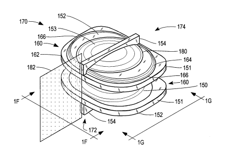
Figures 1D-1G illustrate another embodiment of the
prosthesis endplate of the invention as used in a
prosthesis 170 having an elastomeric core element.
Figure 1D illustrates a perspective view of such a
prosthesis, while Figures 1E, 1F, and 1G illustrate plan,
anterior elevational, and lateral elevational views,
respectively.
The illustrated prosthesis 170 includes an elastomeric
core 150 and two endplates 160. The prosthesis 170 has an
anterior end 172 and a posterior end 174 as implanted in a
spinal motion segment. The endplate 160 comprises a base
plate 162, a first elevated region 152, a second elevated
region 153 and a medial fin 154. In order to illustrate
- 26 -
CA 02664640 2009-03-26
WO 2008/039850 PCT/US2007/079557
the structure of the endplate 160 clearly, it is shown
without the porous coating, e.g., of metallic beads, with
which it is ordinarily provided in order to promote bone
growth after implantation.
The base plate 162 has a peripheral rim 151, generally
sized and configured to fit within the dimensions of an
intervertebral space of a spinal motion segment. A first
or lower elevated region or dome 152 is supported on the
base plate 162 and has a wall or boundary 164, spaced
radially inward from peripheral rim 151. The wall 114 has
lateral extremities 166 generally in the shape of circular
arcs centered on a central or centroid 168 of the first
elevated region 152. The vertical profile of the first
elevated region 152 may have varied shapes. For example,
it may have a profile including a low wall and a generally
planar elevated surface with a smooth transition
therebetween. Alternatively, the profile of the first
elevated region 152 may have a continuous constant or
varied curvature from one extremity of the planform
boundary 164 to the other in a lateral or antero-posterior
orientation, with the evident proviso that such curvatures
must be chosen to meet the planform boundary 164, which has
a lateral dimension greater than an antero-posterior
dimension, as discussed above.
- 27 -
CA 02664640 2009-03-26
WO 2008/039850 PCT/US2007/079557
A second elevated region or dome 153 is supported on
the first elevated region 152. The second elevated region
153 has a generally circular planform 180, with a uniform
curvature to provide a circular dome shape. The planform
and curvatures of the second elevated region 153 may also
be varied, as discussed above for the first elevated region
152.
In the illustrated embodiment, the endplate 160 is
provided with a medial fin 154, which is an optional
element which may be included to provide for greater
torsional stability.
The first elevated region and second elevated region
are generally symmetrical with respect to a median plane
182, illustrated schematically in Figure 1D and in
Figures lE and 1F. The circular arc shape of the lateral
extremities 166 of the wall or boundary 164 allows for ease
of construction of a seat for the endplate 160 in the
vertebral body, as discussed more fully below. The medial-
lateral dimension of the first elevated region 152 is made
greater than its antero-posterior dimension in order to
provide stability against the possibility of torsional
displacement of the prosthesis with respect to the
vertebral body.
- 28 -
CA 02664640 2009-03-26
WO 2008/039850 PCT/US2007/079557
The second elevated region 153 typically has a
generally circular planform in order to conform to the
generally concave shape of the end of the vertebral body.
However, the curvature of the second elevated region 153
may be varied substantially to conform to varying
curvatures of the vertebral end structures, which may
depend on the level of the disc being replaced and the size
of the patient. In any event, such a general dome shape
provides for forming a seat for the endplate 160 in an
adjacent vertebral body while minimizing the amount of
vertebral bone that has to be removed. The second elevated
region 153 may also have any shape symmetrical with respect
to median plane 182, as described above for the first
elevated region 152. It is not excluded that in
exceptional cases, e.g., where the seat for the endplate
160 in a vertebral body cannot be formed by symmetrical
motion of a bone rasp, as discussed below, that the first
and/or second elevated regions might not be completely
symmetrical with respect to the median plane 182.
Certain advantages accrue to the above-described
design of an endplate for an intervertebral prosthesis,
particularly when compared with an endplate having a flat
or single domed endplate. Thus, a flat surface evidently
can provide limited mechanical stability against shear or
- 29 -
CA 02664640 2009-03-26
WO 2008/039850 PCT/US2007/079557
translational motion of the prosthesis with respect to the
vertebral body. A single dome, having similar anterior-
posterior and medial-lateral dimensions, while it enhances
prosthetic stability in shear or simple translation,
remains limited in its ability to prevent rotation of the
endplate with respect to the vertebral body. The inventive
design, by having two elevated regions, or domes, at least
one of which has different medial-lateral and antero-
posterior dimensions, provides for enhanced stability in
both translation and also in rotation. Furthermore, the
relatively simple shapes of the elevated regions, which are
adapted to the relatively simple and straightforward
procedures and tools for formation of a complementary seat
in the vertebral body, provide evident advantages over more
complex shapes that could be devised to provide similar
stability and would require complex surgical procedures for
preparation and implantation.
Figures 2A-2H show the bone rasp tools and apparatus
used to prepare the recess or seat for receiving the
endplate of the invention.
Figure 1A shows an embodiment of a bone rasp tool 201
having a rasp head 202 positioned within an intervertebral
- 30 -
CA 02664640 2009-03-26
WO 2008/039850 PCT/US2007/079557
space between a lower, or caudal vertebra 206 of a spinal
motion segment and the superior or cephalad vertebra (not
shown) of the spinal motion segment. The central portion
of the intervertebral disc has been excised leaving a
residual portion 200 of the annulus fibrosus. The bone
rasp head 202 has a central elevated region 210 having
teeth 212 arranged to form the central portion of a recess
or seat for receiving a prosthesis endplate of the
invention. The rasp has a central projection or post to
serve as a pivot about which the rasp head 202 can be moved
in a reciprocating angular motion as indicated in
Figure 2B. The peripheral portion 214 of the rasp head 202
in this embodiment is devoid of teeth. Accordingly, this
embodiment of the bone rasp is used in a first step to
prepare the central region of the recess.
Figure 2C shows a second embodiment of a bone asp
having a rasp head 203 positioned within a surgically
prepared intervertebral space for forming the peripheral
region of the recess. In this embodiment the central
region 220 is devoid of teeth while the peripheral region
222 is provided with teeth 224 for preparing the peripheral
region of the recess by angular reciprocating motion as
shown in Figure 2D.
- 31 -
CA 02664640 2009-03-26
WO 2008/039850 PCT/US2007/079557
Figure 2E shows an embodiment of the bone rasp having
a head 230 wherein both the central region 232 and the
peripheral region 234 are provided with teeth 236 for
preparing both the central portion and peripheral portions
of the recess at the same time.
Figure 2F shows another embodiment of the bone rasp
having a head 240 positioned with in a surgically prepared
intervertebral space. The head 240 is provided with teeth
242 of differing lengths in differing regions of the head
240, as illustrated in the cross sections Figure 2G and 2H,
for preparing the central and peripheral regions of the
recess at the same time.
Figures 3A-3C illustrate a groove-cutting tool that
can be used to prepare the anterior-posterior groove to
receive a prosthesis fin, e.g., the fin 104. This tool 300
is inserted into the disc cavity after the various rasps
have been used and employs a side-cutting edge 301 to
prepare a groove on both the superior and inferior
surfaces. The tool 300 is introduced with the cutting edge
301 rotated such it does not protrude above the top surface
but rather lies flat within the recess 302, as shown in
Figure 3B. Alternatively, the tool can be provided with a
center guidepost 310, as shownin Figure 3C, which serves
both to position the groove-cutting tool within the
- 32 -
CA 02664640 2009-03-26
WO 2008/039850 PCT/US2007/079557
intervertebral space and to stow the cutter in a place
where it will not damage bone or other tissue when the tool
300 is inserted. Once the tool 300 in place, the shaft 303
is rotated a quarter turn and the edge cutter 301 is
exposed. The shaft 303 is then reciprocated causing the
edge cutter 301 to prepare the appropriate slot in the
vertebra. The inferior vertebra is prepared in a similar
fashion. An alternate design provides for edge cutters on
both superior and inferior surfaces of the tool so that
both slots are prepared in a single operation.
The invention having been described in terms of
certain embodiments, it will be apparent to those skilled
in this art that many changes and alterations can be made
without departing from the spirit or essential
characteristics of tehi invention. The present disclosure
is therefore to be considered as illustrative, and not
restrictive, of the invention.
- 33 -