Note: Descriptions are shown in the official language in which they were submitted.
CA 02664645 2009-03-26
WO 2008/039890 PCT/US2007/079632
TITLE: Double Sided Rack Manipulator Jaw Actuator System
INVENTOR: Todd Granger Holtz
CROSS REFERENCE TO RELATED APPLICATION
[0001] This application claims the benefit of Provisional Application Serial
No.
60/847,625, filed on September 27, 2006.
FIELD OF THE INVENTION
[0002] This invention is directed to a system for actuating manipulator jaws.
This system
employs a double sided rack, each side of which engages a pinion at a first
end of a rotatably
mounted lever. The second end of each lever comprises a jaw region. The
present invention
may be used with subsea manipulators mounted on remotely operated vehicles
("ROV's").
BACKGROUND OF THE INVENTION
[0003] Prior art systems for actuating manipulator jaws comprise "C" shaped
bushings,
herein referred to as a "C bushing" that engages a T plate attached to a
reciprocating piston. In
such prior systems, as the piston extends, the contact between the C bushings
and the t plate is
steadily reduced. In such prior art systems, as the manipulator is used and
the jaws are clamped
around whatever is being pulled, moved, or picked up, this interface between
the piston and link
arms becomes the weak point of the assembly.
[0004] In prior art systems comprising C bushings and a T plate, the force of
an uneven
load on the jaws can cause the T-plate to be pried away from the piston shaft,
causing the bolt
that secures it to bend, thereby causing the C-bushings to become bound up on
the T-plate. This
can result in jamming of the jaws after several actuations. This can
eventually lead to damage to
the C bushings, the T plate and/or the associated bolt.
[0005] In the rack and pinion design used in preferred embodiments of this
invention, the
same forces are applied substantially evenly throughout the range of motion of
the link arms and
piston. Also, if the link arms are loaded unevenly because of shifted or heavy
load, the force is
transferred thru the link arm pinion pivot pin, the rack, and the other link
arm pinion pivot pin.
This is a preferable load distribution to that of the prior art systems
described above.
CA 02664645 2009-03-26
WO 2008/039890 PCT/US2007/079632
DESCRIPTION OF THE DRAWINGS
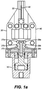
[0006] Figures la-lb are a side views of one preferred apparatus embodiment of
the
invention with the jaws closed and opened, respectively.
[0007] Figure 2 is a side cross sectional view of a preferred embodiment of
the piston
housing and piston suitable for use in practicing the present invention.
[0008] Figure 3 is a side view of a another preferred embodiment of the piston
housing
and piston used in the invention.
[0009] Figure 4 is an isometric view of another apparatus embodiment of the
invention.
[0010] Figure 5 is an exploded isometric view of another apparatus embodiment
of the
invention.
DESCRIPTION OF THE PREFERRED EMBODIMENTS
[0011] A first preferred apparatus embodiment of the invention is directed to
a
manipulator jaw and actuator system. It comprises a piston housing 10
comprising a piston
chamber 12, a fluid inlet 14, and a fluid outlet 16, as shown in Figure 2. In
one preferred
embodiment, the piston housing is cylindrical.
[0012] This apparatus embodiment further comprises a piston 18 having a lower
region
20 slideably mounted in the piston chamber and an upper region 22 extending
beyond the piston
housing, as shown in Figure 2, The piston is mounted in the housing such that
the piston can
reciprocate longitudinally from a final extended position, as shown in Figure
lb, to a final
retracted position, as shown in Figure 1 a, and from a final retracted
position to a final extended
position. The directions of this longitudinal reciprocation is denoted by
arrow Z in Figure 2.
[0013] This apparatus embodiment further comprises a toothed rack 24 mounted
on the
upper region of said piston such that the rack moves with the piston, as shown
in Figures la-lb.
The rack has a first side 26 comprising three toothed fingers 27a-27c facing
in a first direction,
as shown in Figures la-lb, and 5. The rack has a second side 28 comprising
three toothed
2
CA 02664645 2009-03-26
WO 2008/039890 PCT/US2007/079632
fingers 29a-29c facing in a second direction opposite to the first direction,
as shown in Figures
la-lb, and 5.
[0014] This apparatus embodiment further comprises a first lever 30 comprising
a first
upper jaw 32 region and a first lower region 34 pivotally connected to the
piston housing, as
shown in Figures la-lb, and 5. The first lower region comprises a first pinion
36 having at least
three toothed fingers 37a-c positioned to rotatably engage the first side of
the toothed rack such
that the first upper jaw region swings outward when the piston moves from a
final retracted to a
final extended position and swings inward when the piston moves from a final
extended to a final
retracted position, as shown in Figures la-lb, and 5.
[0015] This apparatus embodiment further comprises a second lever 40
comprising a
second upper jaw 42 region and a second lower region 44 pivotally connected to
the piston
housing, as shown in Figures la-lb, and 5. The second lower region comprises a
second pinion
46 having at least three toothed fingers 47a-c positioned to rotatably engage
the second side of
the toothed rack such that the second upper jaw region swings outward when the
piston moves
from a final retracted to a final extended position and swings inward when the
piston moves from
a final extended to a final retracted position, as shown in Figures l a-lb,
and 5.
[0016] In the preferred embodiment shown in Figures la-lb, the first and
second upper
jaws are toothed.
[0017] In another preferred embodiment, the first and second sides of the rack
comprise
two toothed fingers and the lower regions of the first and second levers each
comprise two
toothed fingers.
[0018] In another preferred apparatus embodiment, the rack is split down the
middle into
two components. The first component contains the first side of the rack
described above and the
second component contains the second side of the rack described above.
[0019] In another preferred embodiment, each jaw region comprises multiple
toothed
fingers, as shown in Figure 4. In the preferred embodiment shown in Figure 4,
the multiple
toothed fingers are curved.
3
CA 02664645 2009-03-26
WO 2008/039890 PCT/US2007/079632
[0020] In another preferred embodiment, the invention further comprises a
manipulator
arm attached to the piston housing. In a preferred embodiment, the manipulator
arm is
articulated. In another preferred embodiment, the invention comprises a
remotely operated
vehicle attached to the manipulator arm. In a preferred embodiment, the
remotely operated
vehicle comprises a hydraulic fluid reservoir and pumping system to control
the position of the
manipulator arm and piston.
[0021] It will be understood that various changes in size, shape, detail,
parameters, and
arrangements of the embodiments which have been described and illustrated
above in order to
explain the nature of this invention may be made by those skilled in the art
without departing
from the principle and scope of the invention.
4