Note: Descriptions are shown in the official language in which they were submitted.
CA 02664953 2009-03-31
WO 2008/040055 PCT/AU2007/001471
1
AN APPARATUS AND METHOD FOR FORMING AN OPENING IN A
STORAGE TANK
FIELD OF THE INVENTION
The present invention relates to an apparatus and method for forming an
opening in a storage tank. More particularly, the present invention relates to
an
apparatus and method for safely cutting an opening into a storage tank
containing
a flammable and/or combustible fluid, for example petrol (known in some
countries as gasoline), diesel, avgas, kerosene and the like. The apparatus
and
method is especially suited for cutting an opening in an existing underground
storage tank. It will therefore be convenient to describe the invention in
relation to
this type of storage tank. It should be understood however that the invention
is
intended for broader application and use.
BACKGROUND OF THE INVENTION
Flammable and/or combustible fluids, for example petrol is usually stored
in some form of storage tank. A flammable fluid is a liquid that has a
flashpoint
below 38 Celsius, for example petrol. The flashpoint is the minimum
temperature at which a liquid gives off vapour in sufficient concentration to
form
an air-vapour mixture that can be ignited. A combustible fluid is a liquid
that has
a flashpoint above 38 Celsius. Combustible fluids include diesel and
kerosene.
At retail fuel outlets, for example service or petrol stations for motor
vehicles (referred to in some countries as gas or gasoline stations), one or
more
storage tanks are usually located underground. The underground storage tanks
typically have some form of upstanding access pipe provided which leads from
the storage tank to ground level. The upstanding access pipe is closed at
ground
level by some form of lid. In order to determine the amount of fuel, for
example
petrol, within the storage tank the lid is opened and a measuring stick
inserted.
The measuring stick extends to the bottom of the tank with the petrol marking
the
stick to indicate the depth of the petrol within the tank. The problem in
determining the amount of stored petrol in this manner is that it is labour
intensive
and difficult to obtain an accurate measurement. In addition, it is difficult
to
readily determine from the measurement taken as to whether the storage tank is
leaking as such a determination can not be made without first calculating how
much fuel has been pumped from the storage tank by customers since the last
CA 02664953 2009-03-31
WO 2008/040055 PCT/AU2007/001471
2
measurement was taken. For these reasons, all newly constructed petrol
stations
install some form of automatic measuring system during the construction.
However, in order to install an automatic measuring system to an existing
underground storage tank it is often necessary to firstly install an
additional
upstanding access pipe leading from the storage tank to ground level. This
type
of upstanding access pipe can also be required for a variety of other reasons,
for
example to provide an access point to the storage tank for cleaning purposes.
In the past when an upstanding access pipe, otherwise known as a riser,
was required for an existing underground storage tank the installation
typically
involved cold cutting or drilling a series of holes in an exterior surface of
the
storage tank. Once a suitably sized opening was formed in the storage tank a
riser would then be welded to the exterior surface with the riser extending
upwardly to ground level. As the petrol within the storage tank is highly
flammable installing a riser in this manner is extremely dangerous as a spark
or
flame created during the installation process could easily ignite the petrol.
For
this reason the storage tank has to be emptied prior to the installation of a
riser to
reduce the risk of an explosion occurring. However, an empty storage tank is
still
potentially explosive as even the slightest amount of residual petrol within
an
empty storage tank will result in flammable vapour being released into the
surrounding air. Accordingly, degassing and the introduction of an inert gas
to
the empty storage tank was necessary before installation of the riser could
safely
commence. The process of installing a riser to a storage tank which contains
flammable fluid is therefore complex, time consuming and inconvenient.
Accordingly, it would be desirable to provide an apparatus and method for
safely forming an opening in a storage tank containing a flammable and/or
combustible fluid without having to firstly remove the fluid from the tank.
Any discussion of documents, devices, acts or knowledge in this
specification is included to explain the context of the invention. It should
not be
taken as an admission that any of the material formed part of the prior art
base of
the common general knowledge in the relevant art in Australia or any other
country on or before the priority date of the claims herein.
CA 02664953 2009-03-31
WO 2008/040055 PCT/AU2007/001471
3
SUMMARY OF THE INVENTION
In accordance with a first aspect of the invention there is provided an
apparatus for forming an opening through a storage tank containing a flammable
and/or combustible fluid. The storage tank has a hollow column extending
outwardly from an exterior surface of the storage tank. An interior wall of
the
hollow column in combination with the exterior surface of the storage tank
defines
a well-like cavity allowing access by the apparatus to the exterior surface of
the
storage tank. The apparatus includes a cutting assembly for cutting through
the
exterior surface of the storage tank. The apparatus further includes a housing
assembly for supporting the cutting assembly. The housing assembly includes a
sealing assembly for sealing the housing assembly with respect to the hollow
column such that the cavity is sealed from surrounding air. The housing
assembly further includes a fluid circulation assembly for passing a
circulation
fluid into the cavity such that a non-flammable environment is provided within
the
cavity during cutting of the opening.
The circulation assembly preferably includes an inlet duct for circulation
fluid. The inlet duct extends through a main body of the housing assembly into
the cavity. Preferably, the circulation fluid is nitrogen.
In a preferred embodiment, the cutting assembly includes a cutting head
and a cutting shaft. The cutting head is preferably located at a first end of
the
cutting shaft. The cutting shaft is preferably supported by and extends
through
guide channels in the main body.
In a particularly preferred embodiment, the housing assembly further
includes a shroud extending from a first end of the main body. The cutting
head
preferably projects from the first end of the main body and the shroud
substantially surrounds the cutting head.
In a particularly preferred embodiment, the sealing means a first sealing
arrangement and a second sealing arrangement. The first sealing arrangement
includes an upper and lower wedge member. The upper wedge member may be
attached around a circumference of the main body. The lower wedge member
may extend around a circumference of the upper wedge member. A bottom edge
of the lower wedge member is preferably supported on a top edge of the shroud.
CA 02664953 2009-03-31
WO 2008/040055 PCT/AU2007/001471
4
Preferably, the second sealing arrangement includes a positioning collar
and a locking collar. The positioning collar is locatable around the main body
and
is fastenable on an upper end of the hollow column. Preferably, the locking
collar
extends around the circumference of the main body and is fastenable on the
positioning collar, thereby securing the second sealing arrangement of the
apparatus to the upper end of the hollow column. Further, when the locking
collar
is fastened onto the positioning collar, the lower wedge is preferably forced
radially outwards into sealing engagement with the interior wall of the hollow
column, so that the cavity is sealed from surrounding air. The circulation
fluid can
then be passed into the cavity such that a non-flammable environment is
provided
within the cavity. The cutting head can then cut an opening in the exterior
surface
of the storage tank without the risk of the fluid within the storage tank
igniting.
According to a further aspect of the invention, there is provided a method
of forming an opening through a storage tank containing a flammable and/or
combustible fluid. The storage tank has a column extending outwardly from an
exterior surface of the storage tank. An interior wall of the hollow column in
combination with the exterior surface of the storage tank defines a well-like
cavity.
The method including the steps of:
inserting an apparatus in accordance with the first aspect of the invention,
into the cavity;
sealing the apparatus with respect to the interior wall of the hollow column
such that the cavity is sealed from surrounding air;
providing circulation fluid into the cavity so as to create a non-flammable
environment; and
cutting an opening in the exterior surface of the storage tank.
According to another aspect of the invention, there is provided a method of
forming an opening through a storage tank containing a flammable and/or
combustible fluid. The method including the steps of:
attaching a hollow column to an exterior surface of the storage tank such
that an interior wall of the hollow column in combination with the exterior
surface
of the storage tank define a well-like cavity;
inserting an apparatus in accordance with the first aspect of the invention
into the cavity;
CA 02664953 2009-03-31
WO 2008/040055 PCT/AU2007/001471
sealing the apparatus with respect to the interior wall of the hollow column
such that the cavity is sealed from surrounding air;
providing circulation fluid into the cavity so as to create a non-flammable
environment; and
5 cutting an opening in the exterior surface of the storage tank.
According to yet another aspect of the invention, there is provided a
system for forming an opening through a storage tank containing a flammable
and/or combustible fluid. The system includes a hollow column for attaching to
an exterior surface of the storage tank such that an interior wall of the
hollow.
column in combination with the exterior surface of the storage tank define a
well-
like cavity. The system further includes an apparatus in accordance with the
first
aspect of the invention for cutting the opening within the well-like cavity;
and a
support stand for supporting the apparatus during the cutting of the opening.
BRIEF DESCRIPTION OF THE DRAWINGS
A preferred embodiment of the invention will now be described. The
preferred embodiment should not be considered as limiting any of the
statements
in the previous section. The preferred embodiment will be described with
reference to the following figures in which:
Figure 1 is a front view of the apparatus according to an embodiment of
the invention with the cutting assembly in a retracted position;
Figure 2 is a cross-sectional view of the apparatus shown in Figure 1
illustrating the cutting assembly in the retracted position;
Figure 3 is a front view of the apparatus shown in Figure 1, illustrating the
cutting assembly in an extended (cutting) position;
Figure 4 is a cross-sectional view of the apparatus illustrated in Figure 1,
showing the cutting assembly in the extended (cutting) position;
Figure 5 is an exploded view of the apparatus shown in Figure 1 illustrating
the locking and positioning collars separated from the main body of the
housing
assembly;
Figure 6 is a front view of the cutting assembly of the apparatus illustrated
in Figure 1;
CA 02664953 2009-03-31
WO 2008/040055 PCT/AU2007/001471
6
Figures 7a to 7f are cross-sectional views of the inlet/outlet collar, locking
collar, positioning collar, upper wedge member, lower wedge member, and
shroud, respectively of the apparatus illustrated in Figure 2;
Figure 8 is a front view of a support stand for the apparatus illustrated in
Figure 1;
Figure 9 is a side view of the support stand illustrated in Figure 8;
Figure 9a is a side view of the support stand illustrated in Figure 8 with the
apparatus illustrated in Figure 1 attached thereto and secured in a hollow
column
attached to a storage tank.
Figure 9b is magnified view of a portion of Figure 9a showing the
apparatus secured in the hollow column.
Figure 10 is a rear view of the support stand illustrated in Figure 8;
Figure 11 is a top view of the support stand illustrated in Figure 8;
Figure 12 is a bottom view of the support stand illustrated in Figure 8; and
Figure 13 is a side perspective view of a storage tank having a hollow
column extending outwardly from an exterior surface of the storage tank.
DESCRIPTION OF PREFERRED EMBODIMENT
Referring initially to Figure 13, the apparatus 1 according to the present
invention is applicable for forming an opening through a storage tank 3
containing
a flammable and/or combustible fluid, for example petrol. The storage tank 3
has
a hollow column, which is otherwise known as a riser 7, extending outwardly
from
an exterior surface 9 of the storage tank 3. An interior wall 11 of the riser
7 in
combination with the exterior surface 9 of the storage tank 3 define a well-
like
cavity allowing access by the apparatus 1 to the exterior surface 9 of the
storage
tank 3.
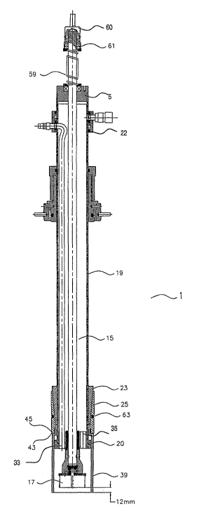
Referring now to Figures 1 to 7, the apparatus 1 includes a cutting
assembly 13 and a housing assembly for supporting the cutting assembly 13. As
can be best seen in Figure 6, the cutting assembly 13 includes a cutting shaft
15
and a cutting head 17 at a first end of the cutting shaft 15. The housing
assembly
includes a main body 19. The main body 19 includes a cylindrical outer shell,
an
upper end cap 5 and a lower end cap 20. At a first end of the main body 19 the
lower end cap 20 is attached to one end of the cylindrical outer shell. At a
second
end of the main body 19 the upper end cap 5 is attached to an opposing end of
CA 02664953 2009-03-31
WO 2008/040055 PCT/AU2007/001471
7
the cylindrical outer shell. The upper and lower end caps 5, 20 each have a
longitudinal guide channel extending therethrough. The cutting shaft 15 of the
cutting assembly 13 is supported by and extends through the guide channels.
The housing assembly further includes a sealing assembly for sealing the
cylindrical outer shell of the main body 19 with respect to the riser 7 such
that
surrounding air is not able to enter the well-like cavity when the apparatus I
is
secured to the riser 7. The sealing assembly includes a first sealing
arrangement
and a second sealing arrangement. The first sealing arrangement is located
near
the first end of the main body 19 and includes an upper wedge member 23 and a
lower wedge member 25. The upper wedge member 23 is securely fixed around
a circumference of the cylindrical outer shell of the main body 19. The lower
wedge member 25 extends around a circumference of the upper wedge member
23 and is movable with respect to the upper wedge member 23. When the
apparatus I is located in the riser 7, the lower wedge member 25 engages with
the interior wall 11 of the riser 7. The lower wedge member 25 is provided
with
an 0-ring 63 to seal the wedge member 25 with respect to the riser 7. The
second sealing arrangement includes a positioning collar 47 and a locking
collar
49. The positioning collar 47 includes an annular recess 51 into which an
upper
edge 53 of the riser 7 is located, such that the positioning collar 47 is
seated on
the riser 7. An O-ring 65 is provided within the annular recess 51 to enable
the
sealing of the positioning collar 47 with respect to the riser 7. The
positioning
collar 47 extends around the circumference of the main body 19 and includes a
threaded section 55 onto which the locking collar 49 is locatable. In this
regard,
the locking collar 49 is provided with a corresponding internal threaded
section 57
to enable the locking collar 49 to be threaded onto the positioning collar 47
thereby locking the apparatus 1 into position on the riser 7. The locking
collar 49
is also provided with an 0-ring 67 to enable the sealing of the locking collar
46
with respect to the cylindrical outer shell of the main body 19.
The housing assembly further includes a circulation assembly for passing
a circulation fluid into the cavity, preferably after the cavity has been
sealed from
the surrounding air by the sealing assembly. The circulation assembly includes
an inlet/outlet collar 22 having an iniet connector 31 and an outlet connector
37.
The inlet/outlet collar 22 is positionable around the cylindrical outer shell
of the
CA 02664953 2009-03-31
WO 2008/040055 PCT/AU2007/001471
8
main body I such that the inlet connector 31 and the outlet connector 37 each
align with corresponding aperture in the outer shell. The circulation assembly
further includes an inlet duct 27 within an internal area of the main body 19
of the
housing assembly. The aperture in the outer shell which aligns with the inlet
connector 31 is connected to one end of the inlet duct 27. The inlet connector
31
is operably connected to a supply source of circulation fluid, which is
preferably
nitrogen or some other inert gas, such that fiuid is thereby supplied through
the
inlet duct 27. An opposing end 33 of the inlet duct 27 extends through the
bottom
end cap 20 to thereby enable the circulation fluid to be fed close to the
cutting
head 17. The bottom end cap 20 further includes an outlet aperture 35 through
which the circulation fluid can be returned back into the internal area of the
main
body 19 and subsequently pass out though the outlet connector 37.
The housing assembly further includes a shroud 39 which projects from
the first end of the main body 19. The shroud 39 substantially surrounds and
lies
adjacent to the cutting head 17. The shroud 39 has a ledge at one end which is
retained behind a projecting rim 26 of the bottom end cap 20 of the main body
19.
At an opposing end of the shroud 39 a' bottom edge 41 of the shroud 39 rests
against the exterior surface 9 of the storage tank 3 when the cutting assembly
13
is in a retracted position, as shown in Figure 2. Although the ledge retains
the
shroud 39 to the main body 19 the shroud 39 is still able to slide a short
distance
with respect to the main body 19 between the projecting rim 26 and the upper
wedge member 23. The ledge of the shroud 39 has a top edge 43 which can abut
with a bottom edge 45 of the lower wedge member 25.
The cutting head 17 of the cutting assembly 13 is movable between a
retracted position, as shown in Figure 2 and an extended or cutting position
as
shown in Figure 4. In the retracted position, the cutting head 17 is set back
approximately 12 mm from the bottom edge 41 of the shroud 39. In the cutting
position, the cutting head extends from the bottom edge 41 of the shroud 39 by
approximately 20mm. Accordingly, the total travel of the cutting shaft 15 is
approximately 32mm. The cutting assembly 13 further includes a spring 59, a
retaining collar 60 and a thrust washer 61. The thrust washer 61 is housed
within
the retaining collar 60. The retaining collar 60 is fastened to the second end
of
the cutting shaft 15. The cutting head 17 is biased to the retracted position
by the
CA 02664953 2009-03-31
WO 2008/040055 PCT/AU2007/001471
9
spring 59 which is located around the cutting shaft 15. In this regard, the
spring
59 extends between the upper end cap 5 of the main body 19 and the retaining
collar 60.
Prior to forming an opening through the storage tank 3 it is first necessary
to mount the riser 7 onto the exterior surface 9 of the storage tank 3. In
this
regard, if the storage tank 3 is located underground, it is first necessary to
excavate the region above the storage tank 3. Once at least an upper section
of
the storage tank 3 is exposed, the riser 7 is chemically bonded, rather than
welded, to the exterior surface 9 of the storage tank. After the riser 7 is
securely
bonded to the exterior surface 9 of the storage tank 3 the riser 7 is filled
to the
upper edge 53 of the riser 7 with water. If no leaks are present the level of
the
water within the riser 7 should remain constant. Once it has been determined
that no leaks are evident the excavated region above the storage tank 3 is
then
backfilled such that only the upper edge 53 of the riser 7 is left exposed. An
end
cap may then be located over the upper edge 53 of the riser 7 for access at a
later date when an opening in the exterior surface 9 of the storage tank 3 is
required.
When an opening in the exterior surface 9 of the storage tank 3 is required,
for example to provide access to the storage tank 3 for the installation of
third-party equipment, electronic tank gauging equipment, tank maintenance
operations or the like, the end cap over the riser 7 is firstly removed.
Provided
that there are no leaks where the exterior surface 9 of the storage tank 3 is
bonded to the riser 7, the level of water within the riser 7 should not have
altered
from when the riser 7 was initially attached to the storage tank 3. If the
storage
tank 3 is partially or completely full of fluid, prior to the commencement of
the
cutting process, the composition of the atmosphere within the storage tank 3
should be checked to ensure that oxygen levels are below 10%. If oxygen levels
are greater than this amount, an inert gas such as nitrogen should be placed
into
the storage tank 3.
The process of cutting an opening in the exterior surface 9 of the storage
tank 3 commences with the insertion of the apparatus 1 into the riser 7. In
this
regard, the apparatus I is lowered into the riser 7 until the bottom edge 41
of the
shroud 39 touches the exterior surface 9 of the storage tank 3. The riser 7 is
CA 02664953 2009-03-31
WO 2008/040055 PCT/AU2007/001471
approximately 100mm in diameter and the apparatus 1 is more than 80mm in
diameter. Accordingly, as the riser 7 is initially full of water a substantial
amount
of the water is displaced from the riser 7 as the apparatus 1 is lowered into
the
riser 7.
5 Once the apparatus 1 has been lowered into the riser 7 the positioning
collar 47 is secured onto the upper edge 53 of the riser 7. As the locking
collar 49
is threaded onto the positioning collar 47, the main body 19 is forced
downwards
towards the exterior surface 9 of the storage tank 3. This causes an inclined
surface of the upper wedge member 23 to slide against a corresponding inclined
10 surface of the lower wedge member 25. As the bottom edge 45 of the lower
wedge member 25 rests on the top edge 43 of the shroud 39, when the main
body 19 is pushed downwards towards the storage tank 3, the upper wedge
member 23 forces the lower wedge member 25 radially outwards towards the
interior wall 11 of the riser 7. As a result, the 0-ring 63 on the lower wedge
member 25 enables the lower wedge member 25 to be sealingly engaged with
the interior wall 11 of the riser 7. Once the locking collar 49 has been fully
threaded onto the positioning collar 47 and tightened, sealing of the
apparatus 1
is complete. Fluid can then only enter the cavity under controlled conditions
via
the inlet duct 27.
Following the sealing of the apparatus 1 to the riser 7 a support stand 69,
as illustrated in Figures 8 to 12, is positioned over the apparatus 1. The
support
stand 67 includes vertically adjustable legs 71 which support a platform 73.
The
platform 73 has an access port 75 through which the apparatus 1 extends. As
can be seen in Figure 12, two opposing clamp members 76 are provided over the
access port 75. The clamp members 76 are able to move towards one another to
thereby securely hold the main body 19 of the apparatus 1.
With reference to Figures 6 and 9a, the cutting shaft 15 is operably rotated
by an air drill attached to a drill shaft 77 formed in one end of the
retaining collar
60. The drill shaft 77 is triangular in cross section and is inserted into a
drill chuck
79 of the air drill. The air drill is controlled via the control box 81 of the
support
stand 69. The control box 81 is mounted to an A-frame 83 via a vertical guide
rail. An upper end of the guide rail is provided with a control wheel 85 which
can
be rotated to rotate the vertical guide rail such that in-turn the vertical
position of
CA 02664953 2009-03-31
WO 2008/040055 PCT/AU2007/001471
11
the control box 81 and drill chuck 79, with respect to the platform 73, is
altered.
An air supply source (not illustrated) is operably connected to the air drill.
A fluid inlet feed line is operably connected to a nitrogen supply source
(not illustrated) and the inlet connector 31 of the inlet/outlet collar 22
with the flow
of nitrogen being controlled via the control panel on the control box 81. A
fluid
outlet feed line is connected to the outlet connector 37 of the inlet/outlet
collar 22.
The outlet feed line leads to a nitrogen flow indicator, gas detector and
vent.
Nitrogen is fed from the nitrogen supply source into the apparatus 1 with
an associated regulator set to 30 kpa. When a pressure monitoring gauge
confirms a pressure of 30 kpa a sample can be taken by connecting a gas
monitor to an appropriate port to determine whether all oxygen has been
depleted
from the sealed section of the cavity. When it is established that no oxygen
is
present in the cavity a non-flammable environment is obtained within the
cavity
and cutting of the opening in the storage tank 3 can safely commence.
A trigger of the air drill is then locked open, to provide full air pressure,
and
an appropriate drill speed is selected. The vertical drilling force applied by
the air
drill is controlled by an operator using a nominated trigger on the air drill.
When
the nominated trigger is activated variable vertical force is applied to the
cutting
shaft 17 of the cutting head 15. The vertical position of the cutting head 15
can
also be controlled by the user rotating the control wheel 85. When the cutting
head 17 has cut through the exterior surface 9 of the storage tank 3 the
rotational
speed of the cutting head 17 will increase. The cutting head 17 is provided
with
magnets which retain the off-cut section of the storage tank 3 preventing it
and
swarf from falling into the storage tank 3.
The supply of compressed air to the air drill is then turned off such that the
air drill stops rotating. The drill chuck 79 is then released from the drill
shaft 77
and the air drill removed from the platform 73. The nitrogen supply source is
then
operably disconnected from the inlet connector 31 of the apparatus 1. The
support stand 67 is then removed from on top of the storage tank 3. Following
removal of the support stand 67 the locking collar 49 is released from the
positioning collar 47 such that the apparatus 1 can be withdrawn from the
riser 7.
The upper edge 53 of the riser 7 can then be fitted with a sealing cap.
CA 02664953 2009-03-31
WO 2008/040055 PCT/AU2007/001471
12
The present invention advantageously enables an opening in a storage
tank 3 containing a flammable and/or combustible fluid to be safely cut
without
generating ignition sources such as sparks and flames. Further, the present
invention advantageously does not require the immediate area to be cleared of
personnel during the cutting process as flammable vapour is prevented from
escaping into the surrounding air. In addition, the present invention does not
require the storage tank 3 to be emptied of flammable fluid prior to the
commencement of the cutting process.
As the present invention may be embodied in several forms without
departing from the essential characteristics of the invention, it should be
understood that the above described embodiment should not be considered to
limit the present invention but rather should be construed broadly within the
spirit
and scope of the invention. Various modifications and equivalent arrangements
are intended to be included within the spirit and scope of the invention.