Note: Descriptions are shown in the official language in which they were submitted.
CA 02664997 2009-03-30
WO 2008/049898 PCT/EP2007/061494
FORCE ESTIMATION FOR A MINIMALLY INVASIVE ROBOTIC SURGERY SYSTEM
Technical field
[0001] The present invention generally relates to the field of minimally
invasive medical
procedures, including surgery and diagnostic procedures. More particularly,
the invention
concerns a method and a system for force estimation that are capable of
determining
forces exerted onto a patient, especially by the tip of a minimally invasive
instrument, but
also at the level of the access port for the instrument into the patient body.
Introduction
[0002] It is well known that minimally invasive interventions have the benefit
of reducing
the amount of extraneous tissue that is damaged during diagnostic or surgical
procedures.
This results in shorter patient recovery time, less discomfort, less
deleterious side effects
and lower costs of the hospital stay. Nowadays, in general surgery, urology,
gynecology
and cardiology specialties, there is an increase of the amount of
interventions carried out
by minimally invasive techniques, such as laparoscopic techniques.
[0003] Manual minimally invasive techniques in general, and laparoscopy in
particular,
put stringent requirements on the surgeon carrying out the operation. The
surgeon
operates in an uncomfortable and tiring posture, with a limited field of view,
reduced
dexterity and poor tactile perception. To these problems adds the fact that
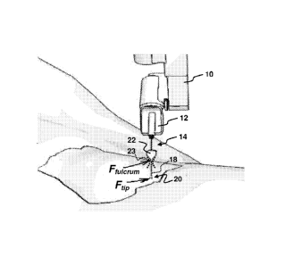
surgeons often
have to carry out several consecutive interventions per day, each intervention
lasting e.g.
from 30 minutes to several hours. In spite of the inherent difficulties, the
trend towards
minimally invasive procedures is expected to increase further in the coming
years due to
an increasing average age of the population and pressure of costs in the
medical field.
[0004] In laparoscopy for example, surgeons are obviously required to be as
precise in
his moves as in laparotomy. Manipulating long-shaft instruments with motion
dexterity
reduced to four degrees of freedom about a fulcrum (pivot point) at the
instrument access
port (also called trocar), i.e. at the incision in the patient body, is not
alleviating their task.
Complications arise inter-alia by the fact that the required posture is often
tiresome and
reduces the already limited perception of interacting forces between
instrument and
tissues. As a result, motorial capabilities of a surgeon normally decay after
20-30 minutes,
such that among others trembling, loss of accuracy and loss of tactile
sensitivity occur
with the resulting risks for the patient. Therefore, new computer and/or robot
assisted
CA 02664997 2009-03-30
WO 2008/049898 PCT/EP2007/061494
2
technologies, such as Minimally Invasive Robotic Surgery (MIRS), are emerging.
These
technologies aim at improving efficiency, quality and safety of intervention.
Background Art
[0005] In view of the above, MIRS has known significant development during the
last
decade. Two representative commercial robotic systems are the system known by
the
trademark `DA VINCI' developed by Intuitive Surgical Inc., Sunnyvale,
California and the
system known by the trademark 'ZEUS' originally developed by Computer Motion
Inc.,
Goleta, California. The system known by the name DA VINCI' is described among
others
by Moll et al. in US 6,659,939; US 6,837,883 and other patent documents of the
same
assignee. The system known by the name 'ZEUS' is described among others by
Wang et
al. in US 6,102,850; US 5,855,583; US 5,762,458; US 5,515,478 and other patent
documents assigned to Computer Motion Inc., Goleta, California.
[0006] These teleoperated robotic systems permit to control surgical
interventions either
directly from the operation theatre or from a remote site, generally using 2-
dimensional or
3-dimensional visual feedback only. In either case, the tiring posture of the
surgeon is
eliminated. Furthermore, these systems tend to give the surgeon the feeling to
work in
open conditions, e.g. as in laparotomy, and eliminate the aforementioned
tiresome
posture.
[0007] Currently available teleoperated MIS systems typically do not offer
true tactile
force feedback (referred to as force feedback below) on the console by means
of which
the surgeon commands the robot(s). Hence the surgeon lacks a true haptic
feeling of the
forces exerted onto organs and tissues. With such systems, the surgeon has to
rely on
visual feedback and on his experience to limit interaction of instruments with
the intra-
patient environment. In this respect, research work has been done concerning a
computer-assisted sensorless force feedback system based on the concept that a
computer could reproduce what a surgeon skilled in manual MIS procedures is
capable of.
In other words, a computer could estimate forces from deformations observed by
vision.
An example of such attempts is found in: "Force feedback using vision";
Kennedy, C. and
Desai, J. P.; International Conference on Advanced Robotics; Coimbra,
Portugal, 2003.
Such systems have however not yet reach a commercially viable state.
[0008] As will be appreciated, accurate force feedback is considered a crucial
feature to
ensure operation safety and to improve the quality of procedures carried out
with machine
assisted minimally invasive systems. Therefore, force feedback is believed to
be of
paramount importance for teleoperated interventions.
CA 02664997 2009-03-30
WO 2008/049898 PCT/EP2007/061494
3
[0009] At the instrument tip level, force sensing allows for example palpation
of organs
and tissues, which is highly desirable in diagnostic procedures and for
identifying critical
areas e.g. with arteries. Other possible enhancements consist in the
limitation of
stretching tension on sutures and the limitation of exerted forces on tissues
according to
the type and specific phase of the intervention. In practice, contact forces
can be kept
below a given threshold by increasing motion scales, stopping the manipulator
motion, or
increasing force feedback on the master device. Furthermore, force sensing
would permit
to work intuitively with an instrument that is not in the field of view of the
endoscope
camera, e.g. when the surgeon assistant holds an organ away from the operation
field.
[0010] At the access port level, force sensing would be beneficial in order to
monitor and
consequently reduce forces applied by the instrument at the incision for the
access port.
These forces are the main cause of incision wear that can lead to loss of
abdominal
pressure, release of the trocar, and increased intervention time due to the
need to recover
the situation. These detrimental forces are mainly caused by the inaccurate
location of the
instrument fulcrum (pivot point), as determined by the system and modified due
to
variations of intra-abdominal pressure, with respect to the patient incision
but also by
motion drifts of the (robot) manipulator due to its positioning inaccuracy. In
manual
interventions, these wearing forces are less pronounced because of the human
capability
to intuitively adjust hand motion with respect to the optimal pivot point in
the incision.
[0011] To overcome the trocar-release problem, the aforementioned DA VINCI
system for
example, uses a trocar attached to the manipulator wrist at the extremity of
the instrument
insertion/extraction slide. This solution does not reduce the risk the
incision wear and
does not improve the loss of abdominal pressure.
[0012] In order to overcome the latter problem at the trocar level, a force-
feedback
adaptive controller, which is capable of automatically adjusting the fulcrum
point of a robot
manipulator on a plane tangent to the abdomen of the patient, has been
developed and
described in the paper "Achieving High Precision Laparoscopic Manipulation
Through
Adaptive Force Control"; Krupa, A. Morel, G. De Mathellin M.; Proceedings of
the 2002
IEEE Intern. Conference on Robotics and Automation; Washington D.C., May 2002.
In
this approach, a sensor on the end-effector of a robot in combination with a
force
controller is used to explicitly regulate the lateral forces exerted onto the
trocar, which
together with the abdominal wall defines the fulcrum, towards zero. This
method and
system are not capable of determining the forces at the tip of the instrument
inserted
through the trocar. Instead, the interaction force at the instrument tip is
assumed to be
negligible. Therefore, this method can be satisfactorily used only with an
endoscope
manipulator that does not have any other contact point with the patient.
CA 02664997 2009-03-30
WO 2008/049898 PCT/EP2007/061494
4
[0013] A different approach is described in the paper: "Development of
actuated and
sensor integrated forceps for minimally invasive robotic surgery"; B. Kubler,
U. Seibold
and G. Hirzinger; Jahrestagung der Deutschen Gesellschaft fur Computer- und
Roboterassistierte Chirurgie (CURAC), October 2004. This paper describes a
miniaturized
6DOF force/torque sensor to be installed at the tip of a minimally invasive
instrument. This
sensor enables accurate sensing of the forces exerted by the instrument tip
and
corresponding force feedback. This concept has several drawbacks however,
among
which manufacturing and installation cost, the lack of robustness in autoclave
sterilization,
and EMI shielding issues when combined with powered instruments. As will be
understood, a dedicated sensor has to be provided on every instrument when
using this
approach. A similar approach has been described in the paper: "A miniature
microsurgical
instrument tip force sensor for enhanced force feedback during robot-assisted
manipulation"; Berke!man, P. J., Whitcomb, L. L., Taylor, R. H., and Jensen,
P.; IEEE
Transactions on Robotics and Automation, October 2003.
[0014] A different approach, which does not require a tip mounted sensor on
every
instrument has been described in the paper "A New Robot for Force Control in
Minimally
Invasive Surgery"; Zemiti N., Ortmaier T. et Morel G.; IEEE/RSJ International
Conference
on Intelligent Robots and Systems, Japan, 2004. This paper describes a robot
and force
sensor arrangement that can measure the distal organ-instrument interaction
with a
sensor placed on the trocar. Even though, in this approach, the sensor is not
mounted on
the instrument itself and is therefore subject to lower miniaturization and
sterilization
constraints, this solution still requires modified trocars with sensor
equipment capable of
resisting sterilization. A further approach designed for MIS, as disclosed in
patent
application WO 2005/039835, uses a master/slave architecture with two PHANTOM
haptic devices developed by SensAble Technologies, Woburn, Massachusetts. This
system comprises a first PHANTOM device integrated into a slave subsystem and
serving
as manipulator for an instrument in combination with an effector sub-assembly
that is
configured for holding and mounting an off-the shelf instrument tip of a
minimally invasive
instrument such as graspers, dissectors, scissors, etc. to the first PHANTOM
device. In
operation, the minimally invasive instrument has a first end mounted to the
effector sub-
assembly and a second end located beyond an external fulcrum that limits the
instrument
in motion. In order to provide measurement of the force vector (ft, fy, fz)
and the moment
(cz) at the end of the instrument tip, a custom made arrangement of various
strain gauges
is provided. Furthermore, the system comprises one or more personal computers
with
application programs for controlling and serving the first PHANTOM device of
the slave
subsystem and a second PHAMTOM device of the master subsystem.
CA 02664997 2009-03-30
WO 2008/049898 PCT/EP2007/061494
Technical problem
[0015] It is an object of the present invention to provide a method and system
that permit
to estimate the force exerted onto, respectively by, the instrument tip in
cost-effective and
efficient manner while avoiding the need for trocar and/or instrument tip
mounted sensors.
5 General Description of the Invention
[0016] To achieve this object, the invention proposes a method of force
estimation and a
minimally invasive medical system, in particular a laparoscopic system,
adapted to
perform this method. The system comprises a manipulator, e.g. a robot
manipulator, that
has an effector unit equipped with a six degrees-of-freedom (6-DOF or 6-axes)
force/torque sensor. The effector unit is configured for holding a minimally
invasive
instrument mounted thereto. In normal use, a first end of the instrument is
mounted to the
effector unit and the opposite, second end of the instrument is located beyond
an external
fulcrum (pivot point kinematic constraint) that limits the instrument in
motion. In general,
the fulcrum is located within an access port (e.g. the trocar) installed at an
incision in the
body of a patient, e.g. in the abdominal wall. According to the invention, the
method
comprises the following steps:
¨ determining a position of the instrument relative to the fulcrum (which
in the present
context especially means continuously updating the insertion depth of the
instrument
or the distance between the (reference frame of the) sensor and the fulcrum);
¨ measuring by means of the 6 DOF force/torque sensor a force and a torque
exerted
onto the effector unit by the first end of the instrument; and
¨ calculating by means of the principle of superposition an estimate of a
force exerted
onto the second end of the instrument based on the determined position, the
measured force and the measured torque.
[0017] The system comprises a programmable computing device, such as a
standard
computer, a Digital Signal Processor (DSP) or a Field Programmable Gate Array
(FPGA),
programmed to determine the instrument position, to process the measurements
made by
the 6 DOF force/torque sensor and to calculate the force estimate as set out
above.
[0018] The method and system enable estimation (which in the present context
especially
means determination of value(s) that may be affected by a small inaccuracy) of
the force
exerted onto a tissue or organ of patient by the second end of the instrument,
i.e. the
instrument tip, which is invasively introduced into the patient through an
access port such
as a trocar. Indeed, the latter force is equivalent to the actio of the
opposite force
CA 02664997 2009-03-30
WO 2008/049898 PCT/EP2007/061494
6
estimated by the method (reactio). As will be appreciated, this method further
enables a
system design, which requires only a single sensor unit that includes the 6-
DOF
force/torque sensor and mounted on the manipulator i.e. outside the patient.
Conveniently, the sensor unit is mounted in force transmission between the
connection
interface for the instrument on the effector unit and the extreme link/member
of the
manipulator that supports the effector unit. In other words, the 6-DOF
force/torque sensor
is arranged for sensing forces and torques exerted onto the effector unit by
the first end
(=mounted end) of the instrument.
[0019] Hence, the present invention overcomes the well established general
opinion that
sensory equipment must be provided at the level of the instrument tip and/or
the trocar in
order to achieve accurate force measurements of forces exerted at the
instrument tip. It
thus eliminates expensive dedicated sensory equipment to be provided on the
tip of every
instrument as well as and on the trocar, that would be subject to stringent
miniaturization
and sterilization constraints. With the presented method and system, the
latter constraints
are overcome, while a surprisingly accurate estimation of the contact force at
the
instrument tip can be achieved.
[0020] It will be understood that the presented method/system can be used in
connection
with a manually operated manipulator (instrument positioning stand) or, more
commonly,
with a robot manipulator. The method/system enables among others a facilitated
implementation of force-feed back and automated safety features in tele-
operated medical
systems, such as minimally invasive robotic surgery and diagnostic systems.
For
example, tactile sensing on a force-reflecting (haptic) master arm of an
operating console
for the surgeon as well as an automated procedure for limiting the maximum
force exerted
by the instrument tip onto a patient's organ(s) and tissue(s) can be
implemented using
information gained with the present method/system.
[0021] In a preferred embodiment, the method comprises determining an initial
reference
position of the instrument relative to the fulcrum. In this embodiment,
determining the
position of the instrument relative to the fulcrum is based on the determined
initial
reference position and on continuous updating using manipulator motion
information. This
effective procedure takes advantage of known information such as coordinate
information
by direct kinematics of a robot manipulator.
[0022] Preferably, the method further comprises the step of calculating by
means of the
principle of superposition an estimate of a force exerted at the fulcrum by
the instrument,
e.g. onto the trocar, based on the determined position, the measured force and
the
measured torque. Knowledge of the force exerted onto the tissue of a patient
at the
CA 02664997 2009-03-30
WO 2008/049898 PCT/EP2007/061494
7
incision level, of which the force exerted at the fulcrum is the reactio (with
opposite sign),
allows among others automated (re)adjustment of the fulcrum coordinates, which
are e.g.
used by a robot controller for reducing stresses and loads exerted onto the
tissue of the
patient at the incision level. Furthermore, an automated procedure for
limiting the
maximum force exerted at the access port level can be implemented.
[0023] Preferably, the effector unit is further equipped with a 6-DOF
accelerometer. In this
case, the method preferably further comprises the steps:
¨ measuring by means of the 6-DOF accelerometer a gravity load and dynamic
loads
exerted onto the 6-DOF force/torque sensor; and
¨ compensating the gravity and/or dynamic loads in the measured force and the
measured torque.
Such compensation allows to improve the accuracy of the desired force
estimate(s) at the
instrument tip and/or at the fulcrum level.
[0024] Advantageously, the method further comprises a calibration procedure
including
the additional steps:
¨ passing the effector unit through a set of poses distributed over a
workspace, in
particular the orientation workspace, of the manipulator;
¨ recording for each pose a measured force and a measured torque; and
¨ determining force and torque measurement offsets based on the recorded
force and
torque measurements.
In a further preferred embodiment, in case the 6-DOF accelerometer is
provided, the
calibration procedure further comprises the steps:
¨ recording for each pose a measured linear acceleration and a measured
angular
acceleration; and
¨ determining linear and angular acceleration measurement offsets based on the
recorded linear and angular acceleration measurements.
The calibration procedure allows determining (electrical) offsets in the
measurement
signals provided by the sensors and further useful system parameters,
knowledge of
which enables further improvements in the accuracy of the desired force
estimate(s).
[0025] For reducing measurement signal noise, the method advantageously
comprises
applying a linear Kalman filter (according to the basic as opposed to e.g. the
non-linear
extended Kalman formulation) to force and torque data measured by the 6 DOF
CA 02664997 2009-03-30
WO 2008/049898 PCT/EP2007/061494
8
force/torque sensor prior to calculating the estimated force or applying a
linear Kalman
filter to the calculated force estimate, i.e. after the estimated force(s)
have been
calculated. Among the many available filter types, the basic linear Kalman
filter has been
found to be a simple, reliable and fast filter for removing signal noise in
the measured
components.
[0026] In case the accelerometer is provided, the method may preferably
comprise the
steps:
¨ applying a primary linear Kalman filter to force and torque data measured
by the 6
DOF force/torque sensor and to linear and angular acceleration data measured
by the
6 DOF accelerometer;
¨ compensating disturbances due to gravity and dynamic loads after
application of the
primary linear Kalman filter;
¨ applying a secondary linear Kalman filter to the compensated force and
torque data.
Every Kalman filter for each force/torque and acceleration component should
cause the
same filter inherent response-delay. In case there is excessive noise in the
force
component estimates after compensation (due to acceleration signals being
noisier than
the force/torque measurements), a secondary filter after disturbance
compensation is
preferred. The primary filter reduces noise-induced falsification during
compensation
whereas the secondary filter allows smoothing the compensation results.
[0027] Preferably, the Kalman filter, respectively the primary and/or
secondary Kalman
filter, is cascaded and has a first linear Kalman filter stage with a process
noise
covariance parameter set to a higher value, preferably in the range between
0.1 and 1,
and a second linear Kalman filter stage with a process noise covariance
parameter set to
a lower value, preferably in the range between 0.001 and 0.1. At a given
measurement
noise covariance, the cascaded filter configuration enables lower total
response-delays
when compared to a single stage filter for a given noise reduction capacity.
[0028] As will be appreciated, the system is adapted for use with a sensorless
minimally
invasive instrument. It further beneficially comprises a sensorless trocar,
preferably with a
magnetic-based air-valve and especially without plastic cap. Furthermore the
system
advantageously comprises a trocar without gas tap which is preferably made to
the major
extent of plastic material so as to save weight.
[0029] The system may comprise a software program stored by the programmable
computing device, which includes program code for performing all the steps of
any one of
the above embodiments of the method when the software program is run on the
CA 02664997 2014-04-30
= = 9 H8322175
programmable computing device. The invention also concerns a software program
product comprising program code stored on a machine-readable storage medium
which, when running on programmable computing device or loaded onto a
programmable computing device, causes the programmable computing device to
perform all the steps of any one of the above embodiments of the method.
Brief Description of the Drawings
[0031] Further details and advantages of the present invention will be
apparent from
the following detailed description, which is not intended to be limiting, with
reference to
the attached drawings, wherein:
Fig.1 is a perspective view of a robot manipulator for a minimally invasive
medical
system according to a preferred embodiment of the invention;
Fig.2 is a partial perspective view of a minimally invasive instrument, the
tip of which
inserted into a patient and the opposite end of which is mounted to an
effector unit of
the robot manipulator of Fig.1 , for illustrating a fulcrum force and a tip
force;
Fig.3 is an enlarged perspective view of the effector unit shown in Fig.2,
illustrating a
reference coordinate frame of a force/torque and acceleration sensor provided
on the
effector unit;
Fig.4 is a block schematic diagram of a cascaded linear Kalman filter;
Fig.5 is a block schematic diagram of a software architecture for performing
the method
according to the invention;
Fig.6 is a state transition diagram of the main task (FSS task) of the
architecture in
Fig.5;
Fig.7 is a flow chart of a sequence of program steps to be carried out
cyclically during
the APPLICATION_LOADS_EVALUATION state of Fig.6;
Fig.8 is a flow chart of an alternative sequence of program steps to be
carried out
cyclically during the APPLICATION_LOADS_EVALUATION state of Fig.6.
CA 02664997 2009-03-30
WO 2008/049898 PCT/EP2007/061494
Detailed Description of Preferred Embodiments
System Components and Mechanical Configuration
[0032] Fig.1 shows the main mechanical components of the minimally invasive
medical
system according to the invention. The system comprises a robot manipulator,
generally
5 identified by reference numeral 10. An effector unit 12 is connected to a
flange of the
manipulator 10. A minimally invasive instrument 14, is mounted with a first
end 16 to the
effector unit as shown in Fig.1. The instrument 14 comprises an elongated
shaft 18 with a
tip 20 forming the second end of the instrument 14. At its tip 20, the
instrument 14
normally comprises a specific tool e.g. grasper, scissor, hook, coagulator,
etc.. The robot
10 manipulator 10 itself provides 6 degrees of freedom (DOF) by means of a
PRP-RRR joint
arrangement for positioning and orienting the effector unit 12, the effector
unit 12 being
mounted to the foremost rotational (R) joint for rotating the minimally
invasive instrument
14 about the 6th DOF of the manipulator 10 which coincides with the
longitudinal shaft axis
of the instrument 14. As will be appreciated, the robot manipulator 10
provides a 6 axis
positioning and orienting device capable of replicating the motion of a
surgeon's hand by
moving the effector unit 12.
[0033] Fig.2 shows the instrument 14, mounted to the effector unit 12 of the
robot
manipulator 10, in operational position for performing a minimally invasive
medical
procedure. As indicated by a dashed line in Fig.2, the shaft 18 of the
instrument 12 is
partially inserted into a patient's body, e.g. into the abdomen of a patient.
The instrument
slideably penetrates through an access port, referred to as trocar 22
hereinafter. The first
end of the instrument 14, i.e. the tip 20 is located beyond a fulcrum,
indicated by cross-
shaped broken lines at 23, (also called pivot point) defined by the trocar 22
which is
inserted into an incision in the patient's abdominal wall and fixed thereto.
[0034] In normal use, the fulcrum is a kinematic constraint that allows
rotation around
three axes (e.g. two orthogonal pivot directions and one rotation about the
instrument
axis, i.e. the Z axis in the SRF defined below) but translation of the
instrument 14 only
along the penetration axis (e.g. of the trocar 22 ¨ Z in the SRF defined
below). The
fulcrum is defined by the access port, e.g. by the trocar 22, and/or the
tissue of the patient
in which the incision is provided, e.g. the patient's abdominal wall.
[0035] Fig.2 schematically indicates two forces FFuk. and F. . F17 is a force
exerted onto the instrument tip 20 and therefore represents the reactio
corresponding to
the (opposite) force (actio) that the instrument tip 20 exerts on an internal
organ or tissue
of the patient. FFukm is a force exerted onto the trocar 22 and therefore
represents the
CA 02664997 2009-03-30
WO 2008/049898 PCT/EP2007/061494
11
reactio corresponding to the (opposite) force (actio) that the trocar 22,
which is subject to
loads exerted thereon by the instrument shaft 18, exerts onto the patient's
abdominal wall.
The proposed method for determining both, F17 and FFukm will be described
hereinafter.
[0036] Although not shown in the figures, the system further comprises a
manipulator
controller, i.e. hardware, e.g. in the form of a main computer, programmed
with software
for operating one or more robot manipulators 10. Furthermore, a command
console for
tele-operation with a force reflection master arm, i.e. a haptic interface for
force-feedback,
is used by an operator, e.g. a surgeon, to command the robot manipulator 10
via the
manipulator controller. As will be understood, the estimate of FTip will be
fed to the haptic
interface for providing force-feedback and to the motion controller for safety
functions. The
motion controller also uses the estimate of FFukrum for safety functions and
for
readjusting the assumed coordinates of the fulcrum 23.
[0037] Fig.3 shows an enlarged view of the effector unit 12 which is arranged
to support
the first end 16 of the instrument 14 (not shown in Fig.3) in mechanically
rigid manner and
further provided with actuating means for actuating certain types of
instruments and signal
and power connection means for electrically connecting the instrument 14 to
the system.
The effector unit 12 comprises a rigid main body 24 including the actuating
and
connection means as well as a socket 26 to which an adapter at the first end
16 of the
instrument 14 (not shown) can be rigidly connected. At its rear end, the main
body 24
comprises a connection flange 28 by means of which it is rigidly fixed to the
sensing plate
of a 12-DOF (i.e. 12 axis) force/torque and acceleration sensor 30, referred
to as F/TAS
hereinafter. The F/TAS 30 may be configured as single sensor unit comprising a
6-DOF force/torque sensor, referred to as F/T sensor hereinafter, for sensing
forces and
25 torques on three orthogonal axes, and a built-in 6-DOF accelerometer,
for sensing linear
and angular acceleration about the three orthogonal axes. Alternatively, a 6-
DOF
force/torque sensor with an appropriately associated separate 6-DOF
accelerometer can
also be used. The F/TAS 30 in turn is rigidly fixed to the robot manipulator
10, as seen in
Fig.1. Instead of the described F/TAS 30, a sensor unit comprising only a 6-
DOF FIT
30 sensor (i.e. no accelerometer) can be used. In the latter case,
acceleration components
can be determined using the second derivative of position coordinates of the
end-effector
(e.g. effector unit 12) obtained e.g. by direct kinematic computation using
articulation
positions. Compensation of dynamic loads as described hereinafter can thus be
achieved
without accelerometer. It may be noted that the effect of gravity can also be
compensated
CA 02664997 2009-03-30
WO 2008/049898 PCT/EP2007/061494
12
without accelerometer since the gravity vector is known and the orientation
and center of
gravity of the payload attached to the F/T sensor can be determined.
[0038] Fig.3 further shows the Cartesian reference coordinate frame of the
F/TAS 30, with
the three orthogonal axes X, Y and Z, hereinafter referred to as SRF (sensor
reference
frame). As will be understood, the 6 DOF of the F/T sensor in the F/TAS 30
correspond to
3 DOF for X, Y and Z force components respectively and 3DOF for moments
(torque
values) about the X, Y and Z axes respectively, in the SRF. In case a separate
6-DOF
accelerometer is attached to a 6-DOF F/T sensor for providing the F/TAS 30,
the
reference coordinate frame of the accelerometer is preferably coincident with
the
reference coordinate frame of the F/T sensor. Otherwise, an additional
transformation
between these two Cartesian frames shall be added in the calculations
described
hereinafter. In the embodiment shown in Figs.1-3, the 12 axis F/TAS 30
comprises a built
in 6-DOF accelerometer. The 6 DOF of the accelerometer correspond to linear
acceleration components along and angular acceleration components about the X,
Y and
Z axes respectively, in the SRF shown in Fig.3.
[0039] As will be understood, the effector unit 12 is rigidly fixed to the
sensing plate of
F/TAS 30 and preferably configured such that the longitudinal (shaft) axis of
a mounted
instrument 14 (cf. Fig.2) is collinear with one axis of the SRF of the F/TAS
30, preferably
the Z axis as seen in Fig.3. Otherwise, an additional transformation shall be
added in the
calculations described hereinafter.
Main disturbance sources and analysis thereof
[0040] The present section gives an overview of main disturbance sources that
affect the
desired estimation of the force at the instrument tip 20, with the system
presented in
Figs.1-3.
[0041] Besides the intrinsic F/T sensor disturbances such as sensor offsets,
electrical
noise and temperature drifts, with the present system there are, as opposed to
other
known force sensing systems (e.g. using a FIT sensor mounted on the instrument
tip), a
number of additional disturbing and masking factors to be taken into account.
As regards
measured force and moment information, these are mainly:
¨ static and dynamic loads exerted onto the F/T sensor: static loads due to
gravity
(weight of the mass attached to the manipulator mounted F/TAS 30), dynamic
loads
due to the velocity and acceleration of the payload attached to the F/T
sensor;
¨ disturbance sources related to the minimally invasive medical
procedure: trocar friction
forces in the penetration and extraction direction due to the trocar gas tap
and the air
CA 02664997 2009-03-30
WO 2008/049898 PCT/EP2007/061494
13
valve, resistance to pivot due to the trocar gas tap, the modification of the
fulcrum 23
(pivot point) due to the variations of abdominal insufflation pressure,
inaccurate
definition of the fulcrum 23, modification of the fulcrum 23 due to inaccuracy
of the
manipulator 10 while moving.
[0042] Disturbing forces produced by the trocar friction: The trocar 22
produces friction
along the penetration/extraction axis. The friction magnitude depends on the
type of air-
valve used in the trocar 22 (e.g. magnetic, spring-based or plastic membrane
type), on the
plastic cap wear, on the material of the instrument shaft 18 and on its
internal lubrication
by irrigation water and viscous intra-abdominal fluids. According to
laboratory trials,
friction caused by magnetic and spring-based air-valves can be approximated by
a
Coulomb friction in a range of 0.5N - 0.9N and does not depend on lubrication
conditions.
In practice, the spring-based air-valve friction depends slightly on its wear,
and is higher
than magnetic air-valves friction by approximately 0.3 N. The plastic membrane
air-valve
and the plastic cap produce a Coulomb friction but also an impulse-like
reaction force
when inverting the instrument direction. This reaction component is opposed to
the motion
direction and is mainly caused by the plastic collar reversal. The membrane
and cap
friction depends on the membrane cut geometry and on the type of material, but
is
attenuated by lubrication of the trocar 22 which increases along with the
intervention time
through instruments moves. In dry laboratory trials using standard trocars,
plastic caps
produce a Coulomb friction in the range of 1N - 1.5N, and plastic membrane air-
valves
give a Coulomb friction in the range of 6N ¨ 10N. In addition, the friction
magnitude is
found to be asymmetric with respect to the penetration and extraction
directions. For
plastic membrane valves, smaller friction amplitude was observed in the
penetration
direction. Therefore, in order to reduce the penetration and extraction
friction at the trocar
22 as much as possible, magnetic-based air-valves, possibly without plastic
cap, are
preferred
[0043] Disturbing forces produced by trocar gas tap: Some types of trocars
have a tap for
insufflating gas. The tap and the connected gas tube can act as obstacles when
pivoting
the trocar 22, resulting in a disturbing resistance force opposed to the pivot
direction. The
magnitude of this force depends on the stiffness of the abdominal wall and is
generally
between 2N and 5 N according to laboratory trials. Hence, use of trocars with
gas tap
should be avoided with the presented system.
[0044] Disturbing force produced by the trocar weight: Multiple-use trocars
are usually
lightweight, from 30g to 80g, and made of stainless steel possibly with some
parts made
of plastic. Trocars with a gas tap have a cylindrical reservoir and are
heavier, ranging from
100g to 180g. The trocar weight can be perceived as a disturbing force along
the
CA 02664997 2009-03-30
WO 2008/049898 PCT/EP2007/061494
14
transversal X and Y axes in the SRF, depending on the orientation of the
trocar 22 with
respect to the gravity vector. Therefore, lightweight trocars made with
plastic parts are
preferred with the proposed system.
[0045] Disturbing forces produced by low intra-abdominal pressure: In nominal
laparoscopy conditions, the abdominal wall is a relatively stiff surface to
which the trocar
22 is attached. In case of low intra-abdominal pressure, the trocar friction
magnitude may
become higher than the resistance offered by the abdominal wall. In this case,
instrument
penetration or extraction can move the trocar 22 inwards or outwards up to the
point
where the abdominal wall tension overcomes the trocar friction. Negative side-
effects are
firstly, that the location of the fulcrum 23 is altered with respect to the
abdominal wall,
whereby disturbing loads during pivoting increase due to the interaction of
the instrument
with the abdominal wall, and secondly, a spring-like load (with a maximum
value equal to
the trocar friction) is applied in the direction opposite to the instrument
motion. In order to
avoid these disturbing forces, the intra-abdominal pressure is preferably
continuously
monitored and maintained. In case of depressurization, a warning is issued in
order to
take appropriate actions, such as adjusting fulcrum position in the
manipulator controller.
[0046] Disturbing forces from inaccuracies in the determination of the fulcrum
location: In
manual laparoscopic surgery, the surgeon naturally moves the instrument with
respect to
the minor tilting resistance point, which is the ideal fulcrum 23 (pivot
point), located at
about the height of the stiffest layer of the abdominal wall, inside the
trocar 22. When
using a robot manipulator 10 for handling the instrument 14, without any
specifically
designed mechanical compliance as regards the fulcrum 23, the fulcrum position
should
be determined by a suitable procedure and taught to the manipulator
controller. In case
the fulcrum position is inaccurately defined, pivoting of the instrument 14
generates
interaction forces with the abdominal wall that can mask the desired
force/torque values at
the instrument tip 20 and/or the fulcrum 23. These masking forces increase
with the
magnitude of the fulcrum position inaccuracy. In addition, such inaccuracy
produces wear
on the incision, which can lead to the release of the trocar 22, in turn
provoking loss of
abdominal pressure and thereby unnecessarily increasing the intervention time
due to the
required recovery of the situation.
[0047] The definition accuracy of the position of the fulcrum 23 depends not
only on the
procedure used to identify its position it but also on the static and dynamic
accuracy of the
robot manipulator 10. In the present application, a +/-2.5mm estimate of
overall fulcrum
and manipulator accuracy could be acceptable considering the incision
dimension and the
elasticity of the abdominal wall. According to an experimental set-up,
definition
CA 02664997 2009-03-30
WO 2008/049898 PCT/EP2007/061494
inaccuracies regarding the fulcrum 23 may lead to disturbances of 2N-10N at
the level of
the trocar 22.
[0048] As a result, an appropriate selection of the type of trocar 22 permits
to avoid the
gas tap disturbance and to reduce friction and weight disturbances along the
axis of
5 instrument shaft 18 to the level of typical human hand sensitiveness
which is around 0.6N.
Real-time monitoring of intra-abdominal pressure variations with respect to
the pressure at
initial fulcrum definition, can detect a variation of the true fulcrum
location due to varying
insufflation conditions. However, the disturbance force at the access port
level (i.e.
fulcrum 23 or pivot point), due to an inaccurate definition of the fulcrum 23
and due to
10 motion inaccuracy of the manipulator 10, can be identified in real-time
through the
proposed method described hereinafter.
[0049] The proposed method and system are able to overcome the encountered
disturbance issues, thereby enabling tele-operation with accurate force feed-
back and a
number of other beneficial safety-related functions based on force
information, obtained
15 exclusively from a sensor arrangement mounted onto the manipulator 10,
i.e. outside the
patient. There is no need for further sensors, neither on the instrument 14
nor on the
trocar 22.
Calculating forces at the instrument tip and at the fulcrum level
[0050] The proposed method permits to provide an accurate estimate of the
forces FTip
at the instrument tip 20 and FFukrum at the fulcrum 23
[0051] An main point of this method is the calculation of the forces F17 and
FFukni. ,
using the force and torque components measured by the F/TAS 30 which, as will
be
understood is located at a remote point with respect to the respective points
of application
of F17 and FFuk. . This calculation furthermore uses a determined position of
the
instrument 14 relative to the trocar 22, e.g. the distance between the fulcrum
23 and the
origin of the SRF of the F/TAS 30 shown in Fig.3. This calculation is based on
several
assumptions and pre-requisites, as follows:
[0052] A. The 6-DOF FIT sensor in the F/TAS 30 measures the three components
of
forces (Fx, Fy, Fz) and the 3 components of moments (Mx, My, Mz) produced by
the load
attached to the F/TAS 30 in a right-hand Cartesian frame as shown in Fig.3
(SRF).
CA 02664997 2009-03-30
WO 2008/049898 PCT/EP2007/061494
16
[0053] B. The instrument 14 is attached to the F/T sensor through a support,
that can
contain one or more actuators for the instrument mechanism as well as further
other
subsystems (i.e. the effector unit 12).
[0054] C. For purposes of ease of description, it is assumed that the
effective reference
frames of the 6-DOF F/T sensor and the the 6-DOF accelerometer of the F/TAS 30
coincide with the SRF shown in Fig.3 in which the Z axis is collinear with the
longitudinal
axis of a mounted instrument 14 and points towards the instrument tip 20, the
Y axis is
parallel to the upper surface of the main body 24 and the origin is located on
the sensing
plate of the F/TAS 30. In case the forces and torques measured by the F/T
sensor are
expressed with respect to another frame, a transformation can be applied to
express the
measured forces and moment values with respect to the SRF.
[0055] D. The values of force and torque components used in the equations
hereinafter
are obtained from originally unfiltered 6-DOF F/T sensor measurements after
subjecting
the latter to compensation of electrical offsets, gravity and acceleration
loads and a
specific filtering process for reducing measurement noise as described
hereinafter.
[0056] E. Only two external contact forces are applied to the instrument 14 as
shown in
Fig.2, i.e. the reaction force at the fulcrum 23 (FFukm. ), which is assumed
to be tangent
to the abdominal wall, and a contact force(FTT ) on the instrument tip 20
which may have
any direction and sense.
[0057] F. The fulcrum reactio expressed in the SRF, noted FFukm. , has a null
Z
component and there are no external moments applied to the fulcrum 23.
[0058] G. The external force applied to the instrument tip 20 is expressed in
the SRF and
noted FT = FT equals the opposite of the force exerted onto the tissue/organ
ip ip
contacting the instrument tip (actio+reactio=0). There are no external moments
applied to
the instrument tip 20.
[0059] H. The distance vector DFukmm from the origin of the SRF to the fulcrum
23 is
known and has a component along the Z axis only. In practice there may be X
and Y
components of a few millimeters if the shaft 18 of the instrument 14 is bent
and therefore
the distance along the Z axis may be slightly inaccurate. This distance vector
DFukm.
can be determined, i.e. continuously updated from an initial reference, using
procedures
outlined hereinafter.
CA 02664997 2009-03-30
WO 2008/049898 PCT/EP2007/061494
17
[0060] I. The distance vector DT from the origin of the SRF to the instrument
tip 20 is
known and is aligned along the Z axis.
[0061] Taking into account the above assumptions, the resulting torque and
moment in
the SRF, respectively noted Ts and Fs , can be calculated using the principle
of
superposition applied to forces and moments by means of the following
equations:
Ts = F Tip x DTool + FFulcrum x DFulcrum (10)
F = F + F (11)
S Tip Fulcrum
[0062] Where D Tool represents the vector from the origin of the SRF to the
instrument tip
20, which is collinear with the Z axis of the SRF.
[0063] Contact force components at the Instrument-tip 20 are determined by
substituting
F Fulcrum in (10), which results in:
Ts (y) ¨ Fs (x) * __________________ D Fulcrum (z)
Tip(x) = (12)
DTP (z)D Fulcrum(Z)
F Tzp. (y) = Ts (x) + Fs (y) * D Fulcrum (z)
(13)
D Fulcrum(Z) ¨ DT (z)
(Z) = F s (z) (14)
[0064] Similarly, force components at the fulcrum 23 are:
T s (y) ¨ F s (x)* D Tip (z)
F Fulcrum(X) = ___________________________________ (15)
D Fulcrum(z) DTP (z)
T s (X) F s (y) * Tip (z)
F Fulcrum (Y) = (16)
DTzp. (Z) ¨ D Fulcrum (Z)
[0065] As will be appreciated, an accurate estimation of the contact forces
FTip and
FFutcrum applied at the instrument tip 20 and at the fulcrum 23 respectively,
allows, among
others, improvements in safety and quality of robotically assisted minimally
invasive
medical procedures. For instance, the assumed location of the fulcrum 23 with
respect to
CA 02664997 2009-03-30
WO 2008/049898 PCT/EP2007/061494
18
which the robot manipulator 10 is moved , can be continuously adjusted by the
robot
control software, in real-time during the procedure, towards a point of
minimum resistance
using F Fulcrum . Furthermore, the contact forces at the instrument tip 20 can
be reflected
by the (master) arm with which the surgeon commands the (slave) robot
manipulator 10,
so as to enable tactile sensing.
Determining the instrument position relative to the fulcrum
[0066] An initial reference position of the instrument relative to the
fulcrum, e.g. distance
DFulcrum 0 can be determined through the procedure set out below, when a given
instrument 14 is inserted for the first time in the trocar 22. Using the
initial reference
distance DFulcrum 0 DFulcrum is subsequently continuously updated (i.e.
determined in
real-time) using the commanded penetration/extraction, which is a function of
the motion
of the manipulator, which in turn is known from the manipulator controller.
[0067] An example of the procedure to determine the initial fulcrum position
(reference
distance DFulcrum 0) is based on the assumption that the fulcrum 23 is the
point of minor
force resistance and can be found using the FIT sensor on the effector unit
12. For this
procedure, it is assumed that the X and Y axes of the SFR lie in the front
plane of the
sensing plate of the F/T sensor while the Z component is collinear with the
instrument
shaft 18. The procedure is outlined as follows:
[0068] Step 1 - Insertion of the instrument 14, that is attached to the
manipulator 10, into
the trocar 22, until the instrument tip 20 is seen on the endoscope monitor
(i.e. exiting the
trocar sleeve).
[0069] Step 2 ¨ Determination of the position of the instrument 14 that gives
the lowest
reaction forces along the X and Y axes of the SRF, by sliding the instrument
14 along
these axes until reaction forces are below a given threshold, e.g. of 0.3N.
Once a suitable
point is found, it can be assumed that the fulcrum 23 is located at a certain
point along the
instrument axis, i.e. on the Z axis.
[0070] Step 3 ¨ Determination of the position of the fulcrum 23 (Z axis
coordinate) on the
instrument axis ( which corresponds to the Z axis) using the lever principle,
where the
distance at which the force is applied is equal to the module of the moment
vector divided
by the module of the force vector.
[0071] Since at step 2, the instrument position corresponds to a near-zero
contact force
(F Fulcrum)' the instrument 14 is pivoted with respect to its tip 20 until a
sufficient contact
CA 02664997 2009-03-30
WO 2008/049898 PCT/EP2007/061494
19
force (about 3N) is reached. At this point the distance is computed according
to the lever
principle. Subsequently, the instrument is pivoted in the opposite direction
until the same
contact force value is measured and the again the distance is computed again.
Thereafter, the instrument 14 is pivoted to its initial position determined in
step 2. The
reference distance DFulcrum 0 between the fulcrum 23 and the origin of the SFR
on sensor
(along the Z axis) is set to the mean value of the last two measurements.
[0072] As both, the position and orientation of the SRF in the world reference
frame and
the initial reference distance DFukn. 0 , giving the position of the fulcrum
23 with respect
to the SRF (i.e. sensor) resting at the location found in step 2, the fulcrum
location with
respect to the world reference frame can be computed through a simple change
of
reference frame (transformation of coordinates).
[0073] Afterwards, all moves (pivot and penetration) can be given with respect
to the
fulcrum 23, and the instrument position relative to the fulcrum 23, e.g. the
distance
between the origin of the SRF and the fulcrum 23, can be updated accordingly
e.g. using
position information from the manipulator controller.
Compensation of offsets and of gravity and dynamics loads
[0074] As will be understood, the force/torque sensor, e.g. in the F/TAS 30,
attached to
the robot manipulator 10, measures not only the contact forces FTip, F Fuicn4m
but also
the gravity load as well as dynamic (i.e. motion-related) loads exerted onto
the
components attached to the sensing plate of the sensor.
[0075] Therefore, the method of force estimation provides for compensations of
these
loads using additional measurements obtained from the 6-DOF accelerometer
associated
to the 6-DOF FIT sensor.
[0076] The compensated force vector Fcomp with respect to the sensor reference
frame
(SRF) is given by:
F = F ¨ F
comp sensor offsets
¨ LoadMass = ( (LinAccsens, ¨ LinAcc offsets)
(17)
+ ((AngAcc ¨ AngAccoff,,)x Load coG)
where:
'sensor is the force vector in the SRF as measured by the FIT sensor;
CA 02664997 2009-03-30
WO 2008/049898 PCT/EP2007/061494
¨ LinAcc sensor is the linear acceleration, including the gravity
acceleration,
measured by the 6-DOF accelerometer in the SRF;
¨ AngAcc sensor is the angular acceleration measured by the 6-DOF
accelerometer
in the SRF;
5 ¨
LoadcoG is the vector of the center of gravity of the load attached to the 6-
DOF
F/T sensor in the SRF, that is estimated as outlined hereinafter;
¨
Foffsets LinAccoffsets and AngAccoffsets are vectors of sensor offsets, that
are
estimated during a calibration procedure outlined hereinafter;
[0077] The compensated torque vector Tcomp with respect to the sensor
reference frame
10 (SRF) is given by:
Tcomp = Tsensorffset
¨TO ¨((LoadcoGxFT)
(18)
+ LoadInertia- (AngAccsensor ¨ AngAcc )1
qvsets
where:
- T sensor is the moment vector in the SRF as measured by the FIT sensor;
¨ TOffset is the moment offset vector, estimated as outlined hereinafter;
15 ¨ FT
equals the third term on the right-hand side of (17) which represents the
force
produced by the effect of gravity and of acceleration-related loads, which
exerts a
torque onto the sensing plate of the F/TAS 30;
¨ LoadInertia is the vector of the load inertia about SRF axes X, Y and Z,
that can
e.g. be estimated by visual tuning in an off-line analysis, i.e. observing the
20
compensation accuracy improvement on a measurement plot for different values
of the inertia vector.
[0078] As regards the effect of Coriolis acceleration, which depends on the
angular
acceleration and linear velocity of a moving frame with respect to a fixed
one, it may be
noted that this effect does not need to be taken into account with the present
system,
because forces and torques are measured with respect to the moving reference
frame of
the FIT sensor (SRF).
CA 02664997 2009-03-30
WO 2008/049898 PCT/EP2007/061494
21
[0079] The effect of the centrifugal acceleration along the instrument stem
axis, i.e. the Z-
axis of the SRF, in the presented system has empirically been found to be less
than 0.2N
for typical instrument moves and less that 0.4N for fast moves in minimally
invasive
procedures. Although mentioned for the sake of completeness, it has been
experimentally
found that this effect can be neglected and is therefore not taken into
account in equations
(17) and (18).
[0080] For a typical system setup, experimental results in no-contact but fast
moves, i.e.
about 60degrees/second for pitch and yaw pivot DOF and 150mm/sec for the
penetration/direction, show that forces are compensated within a +/- 0.25N
window, and
that moments are compensated within a +/- 0.03Nm window approximately.
[0081] As will be understood, the compensated force and torque vector will be
used for
the calculation described in section "Calculating forces at the instrument tip
and at the
fulcrum level", i.e. Fõ.1, = Fs and Tõnip = Ts .
Calibration procedure
[0082] In order to determine system related parameters that affect measurement
accuracy and calculations for force estimation, a suitable fitting technique,
e.g. a least-
squares fitting method, is applied on a series of measured data. In order to
obtain data
series for applying the least-square fitting technique, the robot manipulator
10 is
consecutively positioned through a suitably predefined set of measurement
poses
distributed over the workspace of the robot manipulator 10. At each pose,
corresponding
to a different position and orientation of the F/TAS 30 through different
configurations of
the 6 DOF of the manipulator 10, the robot manipulator 10 is at rest when
measurement
data is read from the sensors of the F/TAS 30. The set of poses is preferably
chosen so
as to cover a sufficient range ("orientation workspace") of the following
orientation angles:
rotation about the Z-axis of the SRF ("roll") and either rotation about the
pitch or the yaw
pivot axis (for instance using a wrist articulation/joint that varies the
sensor orientation with
respect to gravity).
[0083] If appropriately chosen, it is safe to assume that the F/TAS 30 is
factory-calibrated
and that the accuracy and the resolution of the sensor are far beyond the
application
requirements. In this case, the fitting technique applied to the measurement
data series
enables among others accurate identification of (electrical) offsets of force
and torque
component measurements on each axis as well as (electrical) offsets of linear
acceleration component measurement on each axis. Furthermore, the mass
LoadMass and centre of gravity (COG) of the load attached to the sensing plate
of the
CA 02664997 2009-03-30
WO 2008/049898 PCT/EP2007/061494
22
F/TAS 30 can be accurately determined using the calibration procedure as
described
below.
[0084] For the determination of force measurement offsets (Foffsets ), the
effective load
mass (LoadMass), and the linear acceleration offsets (LinAccoffsõ ), the
following
equation is used:
'sensor = Foffsets LoadMass * (LinAcc sensor ¨ LinAcc )
oll3et (21)
where:
''sensoris the force vector, as measured by the F/T sensor, in the SRF;
¨ (LinAcc s,, ¨ LinAcc offsõ) gives the orientation of the gravity force
with respect
the SRF, since the linear acceleration measurement (LinAcc õ.or ) comprises
the
gravity acceleration term in addition to the motion-related acceleration
(=null at
rest) and an electrical offset (LinAcc offset)
¨ LoadMass* (LinAcc s,,¨ LinAcc offsõ) is the weight force vector given by
the
mass of the payload attached to the F/TAS 30 and by its orientation, with
respect
to the SRF
[0085] For the determination of moment measurement offsets (Toffsõs ) and of
the
coordinates of the centre of gravity of the payload with respect to the SRF
(LoadcoG ),
the following equation is used:
Tsensor =LOadcoG X LoadMass* (LinAcc sensor ¨ LinAcc off,e,) + T off,, (22)
[0086] where (LoadMass,LinAcc offset ) are as indicated above, see (21). For
the
determination of the linear acceleration measurement offsets, the equation is:
MODULUS (LinAcc sensor ¨ LinAcc offset) = 1G (23)
where:
¨ G is the gravity constant.
CA 02664997 2009-03-30
WO 2008/049898 PCT/EP2007/061494
23
As will be understood, vector equations (21), (22) and (23) provide 7 scalar
equations with
13 unknowns for every measurement of the F/TAS sensor in a given calibration
pose of
the manipulator 10.
[0087] Since the robot manipulator 10 and hence the F/TAS 30 is at rest in
each pose, i.e.
there is no motion when the measurements are taken, the offsets of the angular
acceleration components can be estimated based on a mean value of angular
acceleration measurements for all poses:
MEAN(AngAccõõõ)¨ AngAcc0ff5et (24)
Where:
¨ AngAcc.or is the angular acceleration vector measured by the accelerometer;
¨ AngAcc offset is the electrical offset vector for the angular
acceleration component
[0088] The pose set shall be selected to cover the orientation workspace of
the
manipulator 10 in the surgical application. For instance, such an orientation
workspace
shall sample the roll angle about the Z axis of the SRF and the orientation
angle given by
the Z axis of the SRF with respect to the gravity axis. Experimentally, a
number of 30
poses, corresponding to 210 equations, has generally been found sufficient for
a
satisfactory approximation of the required system parameters.
[0089] Since electrical offsets can differ at every start-up, the calibration
procedure should
be executed at start-up before using any measurements from the F/TAS 30. As
described
in section "Check of offset drifts", it may be advantageous to repeat the
calibration
procedure also during an intervention in order to take into account offset
drifts. In this
case, the system needs to drive the manipulator 10 through the set of poses,
which has to
be done in safe conditions.
[0090] An interesting aspect of this calibration method is that there is no
need for
knowledge of the position and orientation of the end-effector (e.g. effector
unit 12), which
also means that this method is independent of the robot manipulator accuracy.
Therefore,
for applications where compensated forces have to be measured, e.g. on hand-
held
portable devices, a simple manually actuated, i.e. passive, positioning device
can be
subjected to the present calibration procedure.
[0091] As will be understood, the above calibration procedure with subsequent
approximation (data fitting method) allows among others to determine Foffsets
, Toffsets ,
CA 02664997 2009-03-30
WO 2008/049898 PCT/EP2007/061494
24
LinAcc offseõ and AngAccoffseõ , used in equations (17) and (18) for
compensation of
offsets in the sensor data obtained from the F/TAS 30.
Sensor data filtering
[0092] A filtering technique should be applied to the raw measurement data
obtained by
means of the F/TAS 30. Although in principle many suitable techniques exist,
the
application of the basic classical form and of two variants of the discrete
Kalman filter for
linear stochastic processes is proposed in order to efficiently estimate
acceleration and
force/torque process variables, and in particular to reduce measurement noise
inherent to
the FIT sensor and accelerometer.
[0093] In a minimally invasive medical application using robotic tele-
operation with force-
feedback, apart from removing the signal noise to a satisfactory extent, it is
highly
desirable that the used filtering process complies with two additional
requirements: firstly,
the amplitude gain of filtered signals should be close to 1 (in the system
bandwidth) in
order to ensure force feedback fidelity and, secondly, the additional time
delay that is
introduced by the filter should be as short as possible. Preferably, the total
tele-operation
cycle delay, including the signal filtering delay should be less than 100
milliseconds in
order that the surgeon does not visually notice a delay, e.g. in case of an
instrument to
tissue contact. Moreover, in order to avoid instability, e.g. when touching
hard surfaces
such as bones with the instrument tip 20, the total tele-operation cycle delay
shall
preferably be less than 20 milliseconds.
[0094] It has been experimentally found that a basic (digital) linear Kalman
filter is a
simple and efficient solution. Among others, it provides better noise
rejection and dynamic
behavior than some other filter types, in particular when compared to
classical
Tchebyscheff digital filters commonly implemented in the firmware of
commercial
force/torque sensors. As opposed to an extended Kalman filter type for the
force and
torque data processing, the present approach is applicable in real-time, is
more easily
tuned and avoids the need for knowledge of the non-linear dynamic model of the
robot
manipulator 10 which is difficult to identify precisely.
[0095] Since the aim of the filter is to estimate noisy digital signals which
are measured
separately and are not inter-correlated, an instance of the filter is applied
individually to
each of the following signal components:
¨ Fx, Fy, and Fz for force measurements;
¨ Mx, My and Mz for moment measurements;
CA 02664997 2009-03-30
WO 2008/049898 PCT/EP2007/061494
¨ Ax, Ay and Az for linear accelerations measurements;
¨ Rx, Ry and Rz for angular accelerations measurements.
[0096] According to the basic Kalman filter, every signal can be assumed to be
a process
governed by a linear difference equation:
5 xk= A xk_i + B Uk-1 Wk-1
with a measurement ze9t that is:
zk = H xk + Vk
In the present system we can assume for all signals that H = 1 because the
measurement
is taken of the state directly and u = 0, since there is no control input.
Furthermore we
10 assume for all signals: A = 1 because the state is approximated to be
invariant from step
to step. However, in the case of forces and moments, the state varies
according to gravity
and acceleration loads, and for all other signals, the state is function of
the operator
motion commands, i.e. the behavior of manipulator 10. Therefore, this latter
approximation
assimilates the sources of state variations to process noise.
15 [0097] As will be appreciated, the proposed filter formulation is that
of the basic discrete
Kalman filter implementation which applies to linear stochastic processes. The
related
time update and measurement update equations of this filter implementation can
be found
e.g. in "An introduction to the Kalman Filter"; Greg Welch, Gary Bishop; UNC-
Chapel Hill;
2002, as follows:
K =P P R)
= ki+ K k(;:k
20 = AP k _IAT+Q (I ¨ Kkil)Pis
time update equations measurement update equations
[0098] As regards initialization, the following initialization parameters can
be used for all
signals:
¨ covariance of the measurement noise R = 1.0: although the best value is
the real
25
measurement noise covariance that could be obtained in a sensor calibration
phase,
any strictly positive value (R>0), meaning that the measurement is not
trusted, can be
used. In fact, the system/process noise covariance parameter Q determined
during the
CA 02664997 2009-03-30
WO 2008/049898 PCT/EP2007/061494
26
filter tuning phase compensates for errors in the initial measurement noise
covariance
value R;
¨ initial state value xk_i = first observation;
¨ initial Kalman gain value Kk = 1.0;
¨ initial system process/system noise covariance Qo determined by filter
tuning.
[0099] It has been shown that the Kalman gain Kk converges to the same
constant value
independently from the given parameters process/system noise covariance Q and
measurement noise covariance R, usually after 50 cycles of the recursive
iteration. With
the present system, it has been found experimentally that after 150msec (50
cycles), the
Kalman gain Kk converges towards the constant value, it remains constant after
4.5sec
(1500 cycles) and reaches the 99% window of its constant value after 2.1sec
(700 cycles).
It has further been found that the Kalman gain Kk remains constant
irrespective of the
(amplitude) of dynamic and contact loads affecting force and torque
measurements, which
validates the approach of a basic linear filter formulation.
[00100] As regards filter (parameter) tuning, an approach based on
comparing the
unfiltered signal with the filtered signal on the same real-time plot for
different values of
system/process noise covariance Q and in real tele-operation conditions (e.g.
at 1:1
motion scale, with accelerated moves of the manipulator 10 but without contact
forces
exerted onto the instrument 14) can be used.
[00101] The general purpose of tuning is to obtain a filtered signal
without spikes or
high frequency ripple, that averages the unfiltered signal but with little
response delay on
signal transitions (time-lag). In the present context, response delay means
the filter
inherent time-lag between the filtered signal and the "true" unfiltered signal
observed
during signal variations. For force, torque and acceleration signals which are
used in the
compensation process (see chapter " Compensation of offsets and of gravity and
dynamics loads in sensor data"), all signals should be filtered with the same
covariance
parameters R, Q in order to maintain an identical time-delay behavior for each
signal,
especially as regards signal transitions. Experimentally, this approach proves
to be
consistent and can be justified by the fact that the same physical phenomenon,
i.e. motion
acceleration of the manipulator 10, nearly exclusively determines the dynamic
behavior of
the measured signals.
[00102] As regards a qualitative analysis, it has been demonstrated
that, for static
signals affected by noise, the Kalman filter is as optimal estimator with 1:1
gain. For
dynamic signals, as in the present system, the Kalman filtered signal does not
have
CA 02664997 2009-03-30
WO 2008/049898 PCT/EP2007/061494
27
spikes due to noise because the noise is almost entirely removed, and the
filtered signal
has similarity to an averaged signal with transitions smoothness depending on
the chosen
process noise covariance parameter Q.
[00103] It will be understood that, with a smaller process noise
covariance Q, the
filtered signal becomes smoother because the measurement is less
trusted, and vice
versa. Furthermore, with lower values of the process/system noise covariance Q
set in the
Kalman filter, not only the smoothness of the filtered signal but also the
response delay
caused by the filtering process increases for a given measurement noise
covariance R. It
is however desirable to have both an immediate and a smoothly varying force
estimate,
e.g. for feed-back to the master arm of a tele-operation command console.
Table 1 shows
typical response delays for different process noise covariance parameters Q of
a force
signal (e.g. on the X-axis of the SRF).
X-axis Force signal filtered with Kalman during
tele-operation
Process
covariance Response Response
parameter Q delay in intervals delay in ms
1 0.4 1.172
0.1 3 8.79
0.01 11 32.23
0.001 25 73.25
0.0001 40 117.2
Table 1
[00104] The response delays indicated in Table 1 were evaluated off-line,
with
measurement noise covariance R=1.0, by measuring the time-lag between the
filtered
signal obtained with the basic linear Kalman filter and the signal obtained
using a parallel
backward recursion (RTS) form of the Kalman algorithm, as described in
"Maximum
likelihood estimates of linear dynamic systems"; H. Rauch, F. Tung, and C.
Striebel;
American Institute of Aeronautics and Astronautics Journal; 3(8), 1965,
which optimally
follows the original "true" signal without introducing response-delay.
[00105] In order to reduce the filter inherent response
delay, the cascaded filter
implementation 40 as shown in Fig.4 is proposed. This filter cascade 40
comprises a first
filter stage 42 and a second filter stage 44, each filter stage 42, 44 being a
separate
CA 02664997 2009-03-30
WO 2008/049898 PCT/EP2007/061494
28
implementation of a basic linear Kalman filter as described above. The first
filter stage 42
is configured to lower the covariance i.e. to reduce the peaks (noise spikes)
of the noise
affecting the unfiltered signal but to cause only a relatively short response
delay (e.g. 2-
3ms). The second filter stage 44, is configured to provide a substantially
smooth output
signal and therefore introduces a longer response delay (e.g. 15ms) than the
first filter
stage 42.
[00106]
It has been found that, for a given total response delay, two cascaded filters
improve the smoothness of the filtered signal with respect to a single filter
causing the
same response delay. In order to achieve this, e.g. in a two filter cascade as
shown in
Fig.4, the first filter stage 42 is configured with a system/process error
covariance (Q1) that
is significantly greater than the system/process error covariance of the
second filter stage
44 (Q2) with given identical measurement error covariance R. Thereby, the same
filtering
performance at lower total response delay when compared to a single stage
Kalman filter
can be achieved. In other words, a Kalman filter cascade with a given total
response delay
provides better filtering performance than a single stage Kalman filter with
the same
response delay. By experiment, it has been found e.g. that two cascaded Kalman
filters,
the first and second filter stages 42, 44 being configured with identical
measurement noise
covariance R=1 and different system/process error covariance parameters of
Q1=0.7 and
Q2=0.012 respectively, improve the smoothness of the final filtered signal
with respect to a
single stage filter configured with Q=0.01 and producing the same observed
response
delay (7--. 32ms). Preferred parameter ranges for the noise covariance Q1 and
Q2 of the
first and second filter stage 42, 44 respectively are: 0.1
1 and 0.001 Q2 0.1.
Preferably, the total response delay should not exceed 40ms for reducing the
risk of
instability on hard surfaces contact.
[00107] Therefore, a cascade of at least two linear Kalman filters is
preferred since
it introduces less response delay with respect to a single-pass (one stage)
filter giving the
same filtering performance (signal smoothness). It should be noted that the
respective
filter implementation for each unfiltered signal ((Fx, Fy, Fz); (Mx, My, Mz);
(Ax, Ay, Az);
(Rx, Ry, Rz)) will usually be configured with the same filter parameters (Q,,
R,, etc.) in
order ensure an identical response delay on all signals and, thereby,
synchronized
signals.
Check of offset drifts
[00108]
As will be understood, every component measurement (signal) obtained
from the of F/T sensor and accelerometer in the F/TAS 30 is affected by an
electrical bias
or offset that is normally time-varying and temperature dependent. In
laboratory trials it
CA 02664997 2009-03-30
WO 2008/049898 PCT/EP2007/061494
29
has been found that measurement signals from a 6-DOF foil-based F/T sensor
(with built-
in temperature compensation) stabilize after a warm-up period of about 3
hours, and
remain thereafter within a range of about 1.5% of the full measurement scale.
However,
the offset value for each signal is subject to variation over time and, in
case of a medical,
especially a surgical application, this variation may be unacceptable, as it
alters the
calculation results for estimating the forces as described hereinbefore.
[00109] Therefore, it is proposed to include a procedure for checking
that these
offsets remain within an acceptable range. This can be achieved in simple
manner by
checking whether the compensated force and torque vector Fcomp , Tom,
components
are near zero when no external loads are applied on the payload attached to
the F/TAS
30.
The proposed function can consist in a software implemented procedure carrying
out the
check upon command request. In case of excessive offset drift, the procedure
sends a
warning to the manipulator controller, which should for example ask the
surgeon to initiate
a re-calibration process. Furthermore, this function can be carried during a
surgical
instrument change, either upon a command given on the HMI or automatically,
for
example based on the signal of a surgical instrument presence-detector on the
effector
unit 12.
Software module architecture
[00110] Initially, it may be noted that the software architecture described
hereinafter
is refers to a software module whose purpose is limited to data processing and
calculations for estimation of contact forces at the level of the instrument
tip 20 and at the
level of the fulcrum 23. It does not take into account functions and
mechanisms to the
control of the manipulator 10, the effector unit 12 or other components of the
system. This
module can however be integrated in the software program of a manipulator
controller by
the skilled person.
[00111] The general architecture of the software module is
schematically shown in
Fig.5. It comprises a core process, the FSS (force sensing system) task which
is governed
by a state transition diagram described hereinafter, that can be implemented
in a main
function running either in task context or at interrupt service routine level.
For the sake of
simplicity, it is assumed that the software module runs in a periodic task
synchronized by
a real-time clock through a semaphore as shown in Fig.5. The FSS task is run
at a given
priority in the real-time operating system and with a given stack size. The
software module
has a message queue that is polled at each clock cycle for new messages. There
are
generally two types of messages: command messages to execute a function or
event
CA 02664997 2009-03-30
WO 2008/049898 PCT/EP2007/061494
messages to generate a transition in the state transition diagram (see below).
Command
messages are generated by external modules pertaining to e.g. the manipulator
controller,
whereas event messages are issued internally by the software module itself.
The module
is capable of generating event and command messages directed to other, e.g.
5 manipulator controller modules, for example in order to issue failure
events, command
replies or stop_motion commands.
[00112] In the software module, the main interfaces of the FSS task
are, as shown
in Fig.5:
¨ a message queue, read at every clock cycle;
10 ¨ an interface to hardware boards from which unfiltered force, torque
and acceleration
data is read;
¨ an interface to a real-time data base to read information required by the
functions of
the modules and to write results
¨ an interface for commands and event messages to external modules.
15 State transition diagram (FSS task)
[00113] Fig.6 shows the main five states of the Force Sensing System
(FSS) task
(cf. Fig.5) implemented as finite state machine. In the following, the states
shown in Fig.5
will be briefly described:
[00114] State 1: Hardware and software initialization: this state
concerns the
20 initialization procedures for the software and hardware parts of the
minimally invasive
medical system. These initialization procedures are carried out at power-up
and/or at boot
time of the controller of the manipulator 10. The hardware initialization task
concerns
among others the set-up of the F/T sensor and accelerometer, e.g. of the F/TAS
30, and
the related interface board(s). The software initialization task includes the
steps of
25 allocating resources such as memory for data structures of the
application, and other
operating-system items (i.e. tasks, semaphores, message queues, clocks, etc.).
If the
hardware and software initialization succeed, the system enters an IDLE state,
waiting for
the calibration command. Otherwise, the system enters a FAILED state as shown
in Fig.6.
The result of the initialization operation can be communicated to the
controller of the
30 manipulator 10, either through a software event or through a function
call returned
parameter.
[00115] State 2: IDLE state: the system waits for a command to start
the calibration
process, which has been described in section "Calibration procedure".
CA 02664997 2009-03-30
WO 2008/049898 PCT/EP2007/061494
31
[00116]
State 3: FAULT state: this state is entered in case of any system/software
malfunction or in case of a detected safety risk, the system waits for a
restart command.
Upon entering the FAULT state, an asynchronous message or event is sent to the
manipulator controller in order to warn of this condition.
[00117] State 4: F/T_&_ACCELEROMETER_CALIBRATION state: In this state, the
manipulator 10 is commanded through a predetermined set of poses with
different
positions and orientations (see section "Calibration procedure"). In each
pose, the F/T
sensor and accelerometer data are recorded upon the reception of a 'record'
command.
After the completion of the pose set, upon the reception of a 'compute'
command, the
aforementioned least-squares fitting technique, or any other suitable
approximation
technique, is applied in order to calculate F/T sensor and accelerometer
offsets (Foffsets ,
"offsetsLinAccoffsets and AngAccoffsets ) together with the coordinates of the
centre of
gravity of the attached load. In the unlikely event the calculation fails,
e.g. because of
inconsistent results or because of a user-made abort command of pose set
moves, the
system returns into the IDLE state warning the manipulator controller of this
event.
Otherwise, at the end of the calibration phase, the system passes into the
APPLICATION_ LOADS_EVALUATION state. In case of software or hardware failure
detection, the system passes to the FAULT state.
[00118]
State 5: APPLICATION_LOADS_EVALUATION state: In this state, a
periodic process executes sequentially, but not necessarily in the given
order, the
following operations:
¨ Data filtering, e.g. by means of a discrete Kalman filter cascade for
linear stochastic
processes (see section "Sensor data filtering");
¨ Compensation of the effect of gravity and dynamic loads in F/T sensor
data (see
section "Compensation of offsets and of gravity and dynamics loads");
¨ Determination, i.e. continuous updating based on manipulator 10 motion,
of the
position of the instrument 14 relative to the fulcrum 23 (see section
"Determining the
instrument position relative to the fulcrum")
¨ Calculate an estimate of the forces at the instrument tip 20 and at the
fulcrum
respectively (see section "Calculating forces at the instrument tip and at the
fulcrum
level");
Optionally the following further operations are also executed by the periodic
process:
CA 02664997 2009-03-30
WO 2008/049898 PCT/EP2007/061494
32
¨ Monitoring of compensated loads against predetermined maximum threshold
values
e.g. stored in the real-time data-base. In case of exceeding values, the
function
issues a warning message, or a stop motion command and writes this condition
in the
real-time database; this process can also be applied to the estimated forces
at the
instrument tip 20 and at the fulcrum level (trocar 22) in order to detect
unsafe
conditions or a failure of the F/TAS 30;
¨ Check the drift of sensor offsets (see section "Check of offset drifts");
¨ Monitoring the intra-abdominal insufflation pressure. In case of
depressurization, the
function issues a warning message so that appropriate action ca be taken,
among
which e.g. redefining the position of the fulcrum 23.
[00119]
Fig.7 shows a possible sequence of the above operations in a flow chart.
As seen in Fig.7, a primary linear Kalman filter, of cascaded configuration
e.g. as
described with respect to Fig.4, filters the sensor data prior to compensation
of the
"parasitic loads". After compensation, a secondary linear Kalman filter is
applied to the
force and torque values, in order to further improve the smoothness quality of
the signal at
the input of the operation that calculates the force estimate(s) (Compute FT,
and
F Fulcrum )= Although shown in Fig.7 as executed before the step of
calculating the force
estimates, the operation for determination of the instrument position can be
executed
periodically at another point in the flow. Similarly one or more of the above
optional
operations (indicated by block "..." in Figs.7 and 8) need not necessarily be
executed
subsequent to calculating the force estimates.
[00120]
Fig.8 shows an alternative sequence of the above operations in a flow
chart. As seen in Fig.8, a single filtering operation is applied subsequent to
calculating the
force estimate(s) (Compute FTip and F Fuicn4m ). The filtering operation can
be based on a
cascaded Kalman filter configuration as described with respect to Fig.4.
[00121]
The alternative of Fig.8 reduces the loss of information (under-/overrated
loads) due to filtering, prior to calculation of the force estimate(s), such
that a further
increase in accuracy can be achieved. The embodiment of Fig.7 is preferable in
case the
system is configured for using the effector unit 12 as a control device
("joystick") for
assisted positioning of the manipulator 10 e.g. during insertion of the
instrument 14.
[00122]
In case, a request for recalibration is received, the state of the system is
changed to F/T_&_ACCELEROMETER_CALIBRATION and the periodic process is
CA 02664997 2009-03-30
WO 2008/049898 PCT/EP2007/061494
33
stopped. In case of a software or hardware failure detection, the system is
changed to the
FAULT state and a warning is issued.
[00123] The execution rate of the cyclic process is configured
according to the
applications requirements. For instance, when using the compensated data for
robotic
tele-operation, this process shall preferably be run at the same rate as that
of the set-point
generation for the manipulator 10, e.g. between 300Hz and 1000Hz.
Conclusion
[00124] The presented method/system provide a contribution to robotic
and/or
computer assisted minimally invasive surgery by offering an accurate and cost-
effective
way of estimating the contact forces at the instrument tip and, optionally, at
the trocar
level.
[00125] In laboratory trials of a prototype system, an average
estimation error of
0.25N and a maximum estimation error of 0.65N have been determined. It will be
appreciated, that even though these values were achieved using a prototype
under
development, the estimation error level is satisfactory even for most tasks in
surgical
laparoscopy, since 0.25N is below the sensitivity threshold of the human hand.
Furthermore, it will be appreciated the a total signal delay of 50ms achieved
with the
prototype make the system readily suitable for tele-operation.