Note: Descriptions are shown in the official language in which they were submitted.
CA 02665128 2009-04-01
WO 2008/042390 PCT/US2007/021188
INTRODUCER ASSEMBLY AND METHOD THEREFOR
Related Application
This application claims priority from U.S. Patent Application Serial No.
11/537,919 filed October 2, 2006, which is incorporated herein by reference.
Technical Field
Introducers and introducing assemblies, and more specifically an
introducer assembly including a bonded sheath assembly.
Back2round
Introducer devices provide for access to the vascular system and are
employed for inserting medical devices such as catheters, guidewires, leads,
infusion ports, dialysis ports, dialysis catheters, and others. A typical
procedure
for gaining access to the central venous system or the arterial system with an
introducer is the Seldinger Introduction Method. The Seldinger Method provides
for insertion of a needle into the vasculature of a patient. Once the needle
is in the
vessel, the physician aspirates the needle to assure that the needle is in the
vessel,
and to draw out air present in the bore of the needle. The syringe is removed
and
discarded. A guide wire is inserted through the needle, and the needle is
removed
over the guide wire. The introducer, which includes a dilator and the sheath,
is
placed over the guidewire and inserted into the vessel. With the introducer
and
wire guide in the vessel, the dilator and wire guide are removed leaving only
the
sheath in the vessel. The desired medical device is implanted through the
passage
of the sheath.
CA 02665128 2009-04-01
WO 2008/042390 PCT/US2007/021188
Attorney Docket No. 905.081 WO1
The sheath is optionally removed from the medical device. Some
removable sheaths are formed of slippery material, which is difficult to
effectively
couple or seal with other components. Furthermore, the introducer device
provides access to the vein or artery, and therefore control of bleeding and
the
intake of air is necessary, for example, through use of a valve.
Accordingly, what is needed is an introducer assembly which can
effectively seal against a wide variety of instruments without inhibiting the
throughput of the instrument, or damaging the instrument. What is also needed
is
an introducer assembly which does not distract or interfere with the
implantation
process.
Brief Description of the Drawings
Figure 1A illustrates a perspective view of an introducing assembly as
constructed in accordance with at least one embodiment;
Figure 1B illustrates a cross-sectional view of a portion of an
introducing assembly as constructed in accordance with at
least one embodiment;
Figure 2 illustrates side view of a portion of a sheath assembly as
constructed in accordance with at least one embodiment;
Figure 3 illustrates side view of a portion of a sheath as constructed
in accordance with at least one embodiment.
2
CA 02665128 2009-04-01
WO 2008/042390 PCT/US2007/021188
Attorney Docket No. 905.081 WO 1
Description of the Embodiments
In the following detailed description, reference is made to the
accompanying drawings which form a part hereof, and in which is shown by way
of illustration specific embodiments in which the invention may be practiced.
These embodiments are described in sufficient detail to enable those skilled
in the
art to practice the invention, and it is to be understood that other
embodiments
may be utilized and that structural changes may be made without departing from
the scope of the present invention. Therefore, the following detailed
description is
not to be taken in a limiting sense, and the scope of the present invention is
defined by the appended claims and their equivalents.
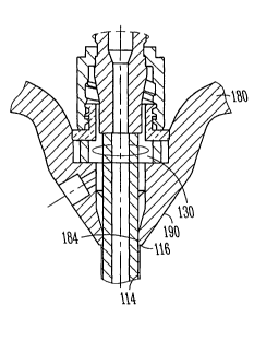
An introducer assembly 100 is illustrated in Figures 1A and 1B. The
introducer assembly includes a sheath assembly 110 having a sheath 112 with a
passage 114 therethrough. The sheath 112 is coupled with a handle assembly 180
as further described below. The sheath 112 extends from a sheath proximal end
portion 116 to a sheath distal end portion 118, and is defined in part by a
longitudinal axis. Near the sheath distal end portion 118 is a tapered
portion,
allowing for a more tapered transition portion to taper to the dilator
disposed
therethrough.
The sheath 112 is formed of, in an example, fluorinated polymers such as,
but not limited to, PTFE (PolyTetraFluoroEthylene), FEP (Fluorinated Ethylene-
Propylene), or polyimide. These materials assist in provided lubricious
surface
proprieties. The sheath material, such as the PTFE, can be molecularly
oriented
for optionally splitting the sheath. The molecularly oriented sheaths do not
necessarily require an additional mechanical scoring operation to produce
split
lines. Instead, the oriented molecules allow the sheath 112 to naturally peel
like a
banana.
3
CA 02665128 2009-04-01
WO 2008/042390 PCT/US2007/021188
Attorney Docket No. 905.081 WO 1
In a further option, the sheath 112 includes various types of sheaths, for
instance, the sheath 112 can comprise a sheath which has a strengthening
material,
such as a strengthening braid of material. Alternatively, the sheath 112
includes a
sheath which is modified to assist in preventing bends and/or kinks along the
sheath.
The introducer assembly 100 further includes an instrument such as a
dilator 120 that can be coupled with the sheath assembly 110, for example,
with a
rotatable coupler 116. For example, the rotatable coupler 116 includes a
threaded
portion that engages a projection or thread on the sheath assembly 110. The
dilator 120 is removably disposed within a passage 114 of the sheath 112, and
optionally is coaxial with the sheath 112. The sheath 112 includes a support
diameter which is sized to receive a dilator 120 having a dilator diameter
therethrough. It should be noted that other instruments such as leads and/or
guidewires can be disposed through the sheath and sheath passage 114, as will
further be described below. The dilator 120 extends from a dilator distal end
to a
dilator proximal end 124, where the dilator distal end is insertable into a
patient,
for example, over a needle or a guidewire. The dilator distal end optionally
ends
in a tapered end, allowing for ease of transition within tissue of a patient.
The
dilator proximal end 124 optionally includes features, such as a luer hub or
threads, that allows for other devices to be coupled thereto.
In one embodiment, the handle assembly 180 and the sheath 112 are
removable from around instruments disposed therein, such as a lead disposed
with
the sheath 112. For example, the sheath 112 is removable from around the
instrument without having to slide or otherwise manipulate the introducer
and/or
the sheath over a proximal end of the instrument. In one option, the handle
assembly 180 and/or the sheath 112 are removed from an outer perimeter along a
cross-section of an instrument disposed therethrough.
4
CA 02665128 2009-04-01
WO 2008/042390 PCT/US2007/021188
Attorney Docket No. 905.081 WO 1
The sheath 112 and/or the handle assembly 180, for example, can be
removed from the instrument disposed therethrough in a number of different
manners. For example, the sheath 112 can include structure integral therewith
or
non-integral that allows for the sheath 112 to be separated from around the
instrument without damaging the instrument, and/or allows for the sheath 112
to
be removed from the outer perimeter of the cross-section of the instrument. In
some examples, the sheath 112 is coupled with a handle assembly 180, and the
handle assembly 180 includes one or more tabs that are connected with the
sheath
112 to tear the sheath 112 off of the instrument. In another example, the
structure
includes a tear strip, molecularly orientated material within the sheath, one
or
more openings in the sheath 112 allowing the sheath 112 to separate at one or
more locations that each can be used alone or in combination to separate the
sheath 112 from around the instrument. In another option, the sheath 112 is at
least partially dissolvable within a body, allowing the sheath 112 to be
removed
from the instrument. In another option, a slitting or splitting device such as
a
slitter can be used to removed the sheath 112, where the sheath 112 is removed
by
slitting. In yet another option, the sheath further includes one, two or more
tabs
which can be used to separate the sheath away from the instrument. Further
options include a pre-weakened or scored sheath, allowing for the sheath to be
manually removed by tearing, separating, or slitting, for example. In yet
another
example, the sheath includes molecularly oriented material allowing for the
sheath
112 to be removed from around the instrument.
The introducer assembly 100 optionally includes a valve 130 that is
sealingly associated with the passage 114 of the sheath 112, allowing for
substantial sealing of the passage 114. The valve 130 assists in preventing
fluids
to exit from a patient when the sheath 112 is disposed within the patient. The
valve 130 assists in preventing fluids from exiting, yet permits passage of
5
CA 02665128 2009-04-01
WO 2008/042390 PCT/US2007/021188
Attorney Docket No. 905.081 WO 1
instruments through the valve 130, and in an option, substantially seals
against the
instruments that are disposed therethrough.
The valve 130 is coupled with a portion of the introducer 110, for
example, within the handle assembly 180 of the introducer. The valve 130, in
an
option, is removable from around an outer cross-sectional perimeter of an
instrument disposed through the introducer. For example, the valve 130 can
include a mechanical weakening allowing for the valve 130 to slide off to the
side
of the instrument. Alternatively, the mechanical weakening can allow for the
valve 130 to be torn or split away from the introducer. In yet another option,
the
valve 130 forms an adaptor that is attachable and removable by the user
before,
during, or after an implant procedure. For example, the user can remove or
attach
the valve assembly 130 with a fitting or other coupling.
As mentioned above, the handle assembly 180 is coupled to the sheath
112, where they are coupled together at an interface 190. In an option, the
interface 190 includes a proximal end portion 116 of the sheath 112 and/or a
portion of the handle assembly 180, such as in inner diameter 184. In an
option,
the interface 190, such as the sheath proximal end portion 116 and/or the
inner or
outer diameter of the handle assembly 180 includes a textured portion 186,
such
as shown in Figure 3. In an option, the textured portion extends around an
outer
circumference of the sheath 112.
The textured portion 186 is formed in an option by chemically etching, for
example, the sheath proximal end portion 116. In an example, the sheath 112 is
rinsed with a solution, such as alcohol. The sheath 112 and/or the handle
assembly 180 are chemically etched with a solution such as, but not limited to
sodium naphthalene / ethylene glycol dimethyl ether solution.
The handle assembly 180 is coupled to the sheath 112, in an example, by
overmolding the handle assembly 180 over the sheath 112. In another option,
the
handle assembly 180 can be preformed, and coupled with the sheath 112 by
6
CA 02665128 2009-04-01
WO 2008/042390 PCT/US2007/021188
Attorney Docket No. 905.081 WO 1
applying energy to the handle assembly 180 and/or the sheath 112, such as
applying heat. During the process, the material of the handle assembly 180
bonds
with the sheath 112, and chemically bonds with the chemically etched portion.
In
a further option, one or more flow holes 119 are formed in the sheath 112,
such as
by punching, prior to coupling the handle assembly 180 thereto. The flow holes
119 allow for material of the handle assembly 180 to flow therethrough, and
further permit a mechanical bond of the handle assembly 180 and the sheath
112.
Advantageously, the introducer assembly described above provides many
benefits. For example, the introducer assembly allows for a sheath, such as a
slippery sheath, to be effectively bonded with a handle assembly, and further
provides a seal between the sheath and the handle. For example, a seal is
provided when the sheath is chemically bonded with the handle assembly.
Furthermore, the methods and coupling techniques increase the tensile strength
of
the sheath to handle the bonding of the sheath and the handle assembly. In
addition, the chemically etched sheath can withstand higher temperatures, for
example temperatures in certain manufacturing procedures, such as, but not
limited to during overmolding processes. The introducer assembly further
allows
for removal of the introducer without disruption to the procedure or placement
of
the medical device such as a lead.
It is to be understood that the above description is intended to be
illustrative, and not restrictive. Many other embodiments will be apparent to
those of skill in the art upon reading and understanding the above
description. It
should be noted that embodiments or portions thereof discussed in different
portions of the description or referred to in different drawings can be
combined to
form additional embodiments of the present invention. The scope of the
invention
should, therefore, be determined with reference to the appended claims, along
with the full scope of equivalents to which such claims are entitled.
7