Note: Descriptions are shown in the official language in which they were submitted.
CA 02665163 2009-03-27
WO 2008/105952 PCT/US2007/080371
FUSE ASSEMBLY FOR SINGLE USE
MEDICAL DEVICE
RELATED APPLICATIONS
This Application claims priority to United States Provisional Patent
Application No. 60/921,497, converted from United States Patent Application
No.
11/581,629 filed October 16, 2006, and is a continuation-in-part of United
States
Patent Application No. 11/435,906 filed May 17, 2006.
BACKGROUND OF THE INVENTION
The present invention relates to a single-use medical device and more
particularly to a two-piece ophthalmic drug delivery device with a disposable
tip end
containing a fuse assembly.
Several diseases and conditions of the posterior segment of the eye threaten
vision. Age related macular degeneration (ARMD), choroidal neovascularization
(CNV), retinopathies (e.g., diabetic retinopathy, vitreoretinopathy),
retinitis (e.g.,
cytomegalovirus (CMV) retinitis), uveitis, macular edema, glaucoma, and
neuropathies are several examples.
These, and other diseases, can be treated by injecting a drug into the eye.
Such injections are typically manually made using a conventional syringe and
needle.
Figure 1 is a perspective view of a prior art syringe used to inject drugs
into the eye.
In Figure 1, the syringe includes a needle 105, a luer hub 110, a chamber 115,
a
plunger 120, a plunger shaft 125, and a thumb rest 130. As is commonly known,
the
drug to be injected is located in chamber 115. Pushing on the thumb rest 130
causes
the plunger 120 to expel the drug through needle 105.
In using such a syringe, the surgeon is required to puncture the eye tissue
with
the needle, hold the syringe steady, and actuate the syringe plunger (with or
without
the help of a nurse) to inject the fluid into the eye. The volume injected is
typically
not controlled in an accurate manner because the vernier on the syringe is not
precise
relative to the small injection volume. Fluid flow rates are uncontrolled.
Reading the
vernier is also subject to parallax error. Tissue damage may occur due to an
"unsteady" injection.
CA 02665163 2009-03-27
WO 2008/105952 PCT/US2007/080371
An effort has been made to control the delivery of small amounts of liquids. A
commercially available fluid dispenser is the ULTRATM positive displacement
dispenser available from EFD Inc. of Providence, Rhode Island. The ULTRA
dispenser is typically used in the dispensing of small volumes of industrial
adhesives.
It utilizes a conventional syringe and a custom dispensing tip. The syringe
plunger is
actuated using an electrical stepper motor and an actuating fluid. With this
type of
dispenser, the volumes delivered are highly dependent on fluid viscosity,
surface
tension, and the specific dispensing tip. Parker Hannifin Corporation of
Cleveland,
Ohio distributes a small volume liquid dispenser for drug discovery
applications made
by Aurora Instruments LLC of San Diego, California. The Parker/Aurora
dispenser
utilizes a piezo-electric dispensing mechanism. While precise, this dispenser
is
expensive and requires an electrical signal to be delivered to the dispensing
mechanism.
U.S. Patent No. 6,290,690 discloses an ophthalmic system for injecting a
viscous fluid (e.g. silicone oil) into the eye while simultaneously aspirating
a second
viscous fluid (e.g. perflourocarbon liquid) from the eye in a fluid/fluid
exchange
during surgery to repair a retinal detachment or tear. The system includes a
conventional syringe with a plunger. One end of the syringe is fluidly coupled
to a
source of pneumatic pressure that provides a constant pneumatic pressure to
actuate
the plunger. The other end of the syringe is fluidly coupled to an infusion
cannula via
tubing to deliver the viscous fluid to be injected.
It would be desirable to have a portable hand piece for injecting a drug into
the
eye. Such a hand piece has a limited reuse assembly attachable to and
removable
from a disposable tip segment. The disposable tip segment contains the drug, a
needle
for administering the drug, and various other components. In order to prevent
infection, the needle of tip segment needs to be sterile. The tip segment
could come
prepackaged in a sterile pack. In order to insure that the disposable tip
segment is
used only once, it would be desirable to have a fused light that prevents the
reuse of
the disposable tip segment.
2
CA 02665163 2009-03-27
WO 2008/105952 PCT/US2007/080371
SUMMARY OF THE INVENTION
In one embodiment consistent with the principles of the present invention, the
present invention is a disposable injection device including a dispensing
chamber, a
plunger, a fuse in series with a light, and a housing. The dispensing chamber
has an
inner surface and an outer surface. The inner surface defines a cavity for
receiving a
quantity of a substance. The plunger is engaged with the inner surface of the
dispensing chamber, is capable of sliding in the cavity of the dispensing
chamber, and
is fluidly sealed to the inner surface of the dispensing chamber. The housing
at least
partially encloses the dispensing chamber and the plunger. After the substance
has
been delivered from the dispensing chamber, the fuse is blown causing the
light to go
out and disabling the device.
In another embodiment consistent with the principles of the present invention,
the present invention is an ophthalmic injection system including a tip
segment and a
limited reuse assembly. The tip segment includes a dispensing chamber, a
plunger, a
fuse in series with a light, and a housing. The dispensing chamber has an
inner
surface and an outer surface. The inner surface defines a cavity for receiving
a
quantity of a substance. The plunger is engaged with the inner surface of the
dispensing chamber, is capable of sliding in the cavity of the dispensing
chamber, and
is fluidly sealed to the inner surface of the dispensing chamber. The plunger
also has
an end with a first mechanical linkage interface. The housing at least
partially
encloses the dispensing chamber and the plunger. The limited reuse assembly
includes a power source, a controller for controlling the operation of the
system, a
actuator having a shaft, a second mechanical linkage interface located on an
end of
the shaft, and a second housing at least partially enclosing the controller
and the
actuator. After the substance has been delivered from the dispensing chamber,
the
fuse is blown causing the light to go out and disabling the device.
In another embodiment consistent with the principles of the present invention,
the present invention is a method of operating an ophthalmic injection system.
The
method includes recognizing a connection between a tip segment and a limited
reuse
assembly and determining if a fuse has been blown. If the fuse has not been
blown,
then a light is illuminated indicating that the tip segment is ready to be
used. After the
tip segment has been used, a current to the fuse is increased thus causing the
fuse to
be blown.
3
CA 02665163 2009-03-27
WO 2008/105952 PCT/US2007/080371
In another embodiment consistent with the principles of the present invention,
the present invention is a medical device having a single use component and a
limited
reuse assembly. The single-use component has a fuse connected in series with a
light
and an interface for receiving electric current that is provided to the fuse
and the light.
The limited reuse assembly is attachable to and removable from the single-use
component. The limited reuse assembly has a controller for controlling the
operation
of the single-use component and a power source for providing the electric
current to
the fuse and the light via the interface. After the single-use component has
been used,
the fuse is blown thus disabling the single use component.
In another embodiment consistent with the principles of the present invention,
the present invention is a single-use medical device including a fuse
connected in
series with a light and an interface for receiving electric current. The
electric current
is provided to the fuse and the light. After the device has been used, the
fuse is blown
thus disabling the device.
It is to be understood that both the foregoing general description and the
following detailed description are exemplary and explanatory only and are
intended to
provide further explanation of the invention as claimed. The following
description, as
well as the practice of the invention, set forth and suggest additional
advantages and
purposes of the invention.
BRIEF DESCRIPTION OF THE DRAWINGS
The accompanying drawings, which are incorporated in and constitute a part
of this specification, illustrate several embodiments of the invention and
together with
the description, serve to explain the principles of the invention.
Figure 1 is a perspective view of a prior art syringe.
Figure 2 is a view of an ophthalmic hand piece including a drug delivery tip
segment and a limited reuse assembly according to an embodiment of the present
invention.
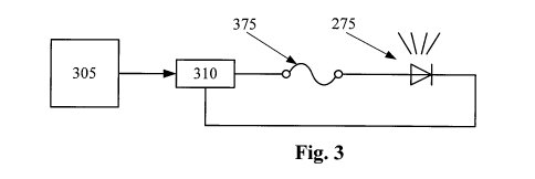
Figure 3 is a diagram of a fused light for use in a drug delivery tip segment
according to an embodiment of the present invention.
4
CA 02665163 2009-03-27
WO 2008/105952 PCT/US2007/080371
Figure 4 is an exploded cross section view of a drug delivery tip segment for
an ophthalmic hand piece according to an embodiment of the present invention.
Figure 5 is cross section view of a drug delivery tip segment and a limited
reuse assembly according to an embodiment of the present invention.
Figure 6 is a flow chart depicting one method of operation of the present
invention.
DETAILED DESCRIPTION OF THE PREFERRED EMBODIMENTS
Reference is now made in detail to the exemplary embodiments of the
invention, examples of which are illustrated in the accompanying drawings.
Wherever possible, the same reference numbers are used throughout the drawings
to
refer to the same or like parts.
Figure 2 depicts one view of an ophthalmic hand piece including a drug
delivery tip segment and a limited reuse assembly according to an embodiment
of the
present invention. In Figure 2, the hand piece includes a tip segment 205 and
a
limited reuse assembly 250. The tip segment 205 includes a needle 210, a
housing
215, a plunger connection 225, and an optional light 275. The limited reuse
assembly
250 includes a housing 255, a switch 270, a lock mechanism 265, and a threaded
portion 260.
Tip segment 205 is capable of being connected to and removed from Limited
reuse assembly 250. In this embodiment, tip segment 205 has a threaded portion
on
an interior surface of housing 215 that screws onto the threaded portion 260
of limited
reuse assembly 250. In addition, lock mechanism 265 secures tip segment 215 to
limited reuse assembly 250. Lock mechanism 265 may be in the form of a button,
a
sliding switch, or a cantilevered mechanism. Other mechanisms for connecting
tip
segment 205 to limited reuse assembly 250, such as those involving structural
features
that mate with each other, are commonly known in the art and are within the
scope of
the present invention.
Needle 210 is adapted to deliver a substance, such as a drug, into an eye.
Needle 210 may be of any commonly known configuration. Preferably, needle 210
is
designed such that its thermal characteristics are conducive to the particular
drug
5
CA 02665163 2009-03-27
WO 2008/105952 PCT/US2007/080371
delivery application. For example, when a heated drug is to be delivered,
needle 210
may be relatively short (several millimeters) in length to facilitate proper
delivery of
the drug.
Switch 270 is adapted to provide an input to the system. For example, switch
270 may be used to activate the system or to turn on a heater. Other switches,
buttons, or user-directed control inputs are commonly known and may be
employed
with limited reuse assembly 250 and / or tip segment 205.
Optional light 275 is illuminated when tip segment 205 is ready to be used.
Optional light 275 may protrude from housing 215, or it may be contained
within
housing 215, in which case, optional light 275 may be seen through a clear
portion of
housing 215. In other embodiments, optional light 275 may be replaced by an
indicator, such as a liquid crystal display, segmented display, or other
device that
indicates a status or condition of the tip segment. For example, optional
light 275
may also pulse on and off to indicate other states such as but not limited to
a system
error, fully charged battery, insufficiently charged battery or faulty
connection
between the tip segment 205 and limited use assembly 250.
Figure 3 is a diagram of a fused light for use in a drug delivery tip segment
according to an embodiment of the present invention. In Figure 3, optional
light 275
and fuse 375 are connected in series with power source 310. Controller 305
controls
the operation of power source 310.
In the embodiment of Figure 3, optional light 275 is a light emitting diode of
any appropriate color. In other embodiments, optional light 275 may be a lamp,
a
phosphorescent light, or any other similar electric or electronic light
source. In other
embodiments, optional light 275 is any type of indicator, such as a liquid
crystal
display or a segmented display.
Fuse 375 is a fuse with a current rating greater than the operating current of
optional light 275. Fuse 375 may be a common glass encapsulated fuse, a trace
fuse
on a printed circuit board, or other similar structure that provides the
function of a
fuse. For example, a switch or switching circuit may be used to provide the
functionality of fuse 375.
Power source 310 is typically a rechargeable battery with associated
electronics. In other cases, power source 310 is a disposable battery or
simply a
6
CA 02665163 2009-03-27
WO 2008/105952 PCT/US2007/080371
connection to an independent power source, such as a switch mode power supply.
In
this embodiment, power source 310 also includes the charging and current
driving
electronics associated with it.
Controller 305 is typically an integrated circuit with power, input, and
output
pins capable of performing logic functions. In various embodiments, controller
305 is
a targeted device controller. In such a case, controller 305 performs specific
control
functions targeted to a specific device or component, such as a heater or a
power
supply. For example, a heater controller has the basic functionality to
control a
heater. In other embodiments, controller 305 is a microprocessor. In such a
case,
controller 305 is programmable so that it can function to control more than
one
component of the device. In other cases, controller 305 is not a programmable
microprocessor, but instead is a special purpose controller configured to
control
different components that perform different functions. In the embodiment of
Figure
3, controller 305 controls power supply 310 and reads data from memory device
315.
While depicted as one component in Figure 1, controller 305 may be made of
many
different components or integrated circuits.
Figure 4 is an exploded cross section view of a drug delivery tip segment for
an ophthalmic hand piece according to an embodiment of the present invention.
In
Figure 4, the drug delivery tip segment includes housing 215, needle 210,
optional
light 275, fuse 375, plunger shaft 410, plunger tip 415, mechanical linkage
interface
420, dispensing chamber 405, dispensing chamber housing 425, heater 450,
thermal
sensor 460, and optional luer 430.
In the embodiment of Figure 4, mechanical linkage interface is located on one
end of plunger shaft 410. Plunger tip 415 is located on the other end of
plunger shaft
410. Plunger shaft 410 and plunger tip 415 collectively form a plunger.
Dispensing
chamber 405 is enclosed by dispensing chamber housing 425 and plunger tip 415.
Plunger tip 415 forms a fluid seal with the interior surface of dispensing
chamber
housing 425. Needle 210 is fluidly coupled to dispensing chamber 405. In this
manner, a substance located in dispensing chamber 405 can be contacted by
plunger
tip 415 and pushed out of needle 210. Needle 210 may be secured to the drug
delivery tip segment by an optional luer 430 or may be permanently attached.
Heater
450 is located on dispensing chamber housing 425 and at least partially
surrounds
dispensing chamber 405. Housing 215 forms an outer skin on the drug delivery
tip
segment and at least partially encloses plunger shaft 410, plunger tip 415,
dispensing
chamber 405, and dispensing chamber housing 425. Optional light 275 is visible
7
CA 02665163 2009-03-27
WO 2008/105952 PCT/US2007/080371
from outside of housing 215. Optional light 275 may be illuminated, for
example,
when the tip segment is ready to be used. Fuse 375 is connected in series with
optional light 275.
A substance to be delivered into an eye, typically a drug, is located in
dispensing chamber 405. In this manner, the substance is contacted by the
inner
surface of dispensing chamber housing 425 and one face of plunger tip 415.
Typically, dispensing chamber 405 is cylindrical in shape. Heater 450 is in
thermal
contact with dispensing chamber housing 425. In this manner, heater 450 is
adapted
to heat the contents of dispensing chamber 425. Current is applied to heater
450
through an electrical interface (not shown). Thermal sensor 460 provides
temperature
information to assist in controlling the operation of heater 450.
In one embodiment of the present invention, the substance located in
dispensing chamber 405 is a drug that is preloaded into the dispensing
chamber. In
such a case, the drug delivery tip segment is appropriate as a single use
consumable
product. Such a disposable product can be assembled at a factory with a dosage
of a
drug installed. A precise volume of a substance can be preloaded into the
delivery
device.
When the drug is preloaded into dispensing chamber 405, a set quantity of the
drug can be preloaded. For example, 100 microliters of a drug can be loaded
into
dispensing chamber 405, and any quantity up to 100 microliters can be
dispensed. In
such a case, the plunger (plunger shaft 410 and plunger tip 415) can be moved
a
precise distance to deliver a precise dosage of drug from the dispensing
chamber 405,
through the needle 210, and into an eye. This provides for flexibility of
dosing and
for ease of assembly.
In operation, the drug delivery tip segment of Figure 4 is attached to a
limited
reuse assembly (not shown). The limited reuse assembly provides power to the
tip
segment and illuminates optional light 275. In such a case, a current passes
through
optional light 275 and fuse 375. Mechanical interface 420 mates with a
mechanical
interface on the limited reuse assembly. When a force is applied to plunger
shaft 410,
plunger tip 415 is displaced. The displacement of plunger tip 415 in turn
displaces the
substance contained in dispensing chamber 405. The substance is pushed out of
needle 210. After the dosage is delivered, the controller (not shown) directs
an
increased current to be sent through fuse 375 and optional light 275. This
increased
current burns out fuse 375 indicating that the tip segment has been used and
is to be
8
CA 02665163 2009-03-27
WO 2008/105952 PCT/US2007/080371
discarded. Any number of commonly known methods can be used to increase the
current to blow fuse 375. Since the tip segment of the depicted embodiment is
a
single use tip segment, once fuse 375 is blown, the tip segment is no longer
operable.
Figure 5 is cross section view of a drug delivery tip segment and a limited
reuse assembly according to an embodiment of the present invention. Figure 5
shows
how tip segment 205 interfaces with limited reuse assembly 250. In the
embodiment
of Figure 5, tip segment 205 includes fuse assembly 555, mechanical linkage
interface
420, plunger 505, dispensing chamber housing 425, tip segment housing 215,
heater
450, thermal sensor 460, needle 210, dispensing chamber 405, interface 530,
and tip
interface connector 520. Limited reuse assembly 250 includes mechanical
linkage
545, actuator shaft 510, actuator 515, power source 310, controller 305,
limited reuse
assembly housing 255, interface 535, and limited reuse assembly interface
connector
525.
In tip segment 205, mechanical linkage 420 is located on one end of plunger
505. The other end of plunger 505 forms one end of dispensing chamber 405.
Plunger 505 is adapted to slide within dispensing chamber 405. An outer
surface of
plunger 505 is fluidly sealed to the inner surface of dispensing chamber
housing 425.
Dispensing chamber housing 425 surrounds the dispensing chamber 405.
Typically,
dispensing chamber housing 425 has a cylindrical shape. As such, dispensing
chamber 405 also has a cylindrical shape. In tip segment 205, fuse assembly
555
includes a fuse and an optional light connected in series as shown in Figure
3.
Needle 210 is fluidly coupled to dispensing chamber 405. In such a case, a
substance contained in dispensing chamber 405 can pass through needle 210 and
into
an eye. Heater 450 at least partially surrounds dispensing chamber housing
425. In
this case, heater 450 is adapted to heat dispensing chamber housing 425 and
any
substance contained in dispensing chamber 405. In other words, heater 450 is
in
thermal contact with dispensing chamber housing 425. Interface 530 connects
heater
450 with tip interface connector 520.
The components of tip segment 205, including dispensing chamber housing
425, heater 450, and plunger 505 are at least partially enclosed by tip
segment housing
215. In one embodiment consistent with the principles of the present
invention, a seal
is present on a bottom surface of tip segment housing 215. In this manner,
plunger
505 is sealed to tip segment housing 215. This seal prevents contamination of
any
substance contained in dispensing chamber 405. For medical purposes, such a
seal is
9
CA 02665163 2009-03-27
WO 2008/105952 PCT/US2007/080371
desirable. This seal can be located at any point on plunger 505 or on
dispensing
chamber housing 425. In such a case, tip segment housing 215 maybe connected
to
dispensing chamber housing 425 to form an air tight or fluid tight seal. In
another
embodiment, tip segment housing 215 may be sealed to plunger 505 near the end
on
which mechanical linkage interface 420 resides. In such a case, an air tight
or fluid
tight seal may be formed between a location on plunger 505 and tip segment
housing
215.
In addition, tip segment 205 may contain a plunger stop mechanism. As
shown in Figure 5, the bottom portion of plunger 505 (the portion on which
mechanical linkage interface 420 resides) is adapted to contact the bottom
portion of
dispensing chamber housing 425. In such a case, as plunger 505 advances upward
toward needle 210, mechanical linkage interface 420 also advances upward
toward
needle 210. A top surface of mechanical linkage interface 420 contacts a
bottom
surface of dispensing chamber housing 425. In this embodiment, the protrusions
on
the bottom end on plunger 505 and the bottom surface of dispensing chamber
housing
425 form a plunger stop mechanism. Plunger 505 cannot be advanced any further
than the point at which the top surface of mechanical linkage interface 420
contacts
the bottom surface of dispensing chamber housing 505. Such a plunger stop
mechanism can provide a safety feature, such as to prevent plunger 505 from
contacting needle 210 and possibly dislodging it. In another embodiment
consistent
with the principles of the present invention, such a plunger stop mechanism
may also
include a locking mechanism so that plunger 505 cannot be retracted or moved
away
from needle 210 when needle 210 is removed from the eye. Such a plunger lock
mechanism helps to prevent reflux of the substance when needle 210 is removed.
In limited reuse assembly 250, power source 310 provides power to actuator
515. An interface (not shown) between power source 310 and actuator 515 serves
as
a conduit for providing power to actuator 515. Actuator 515 is connected to
actuator
shaft 510. When actuator 515 is a stepper motor, actuator shaft 510 is
integral with
actuator 515. Mechanical linkage interface 545 is connected to actuator shaft
510. In
this configuration, as actuator 515 moves actuator shaft 510 upward toward
needle
210 mechanical linkage 545 also moves upward toward needle 210.
Controller 305 is connected via interface 535 to limited reuse assembly
interface connecter 525. Limited reuse assembly interface connecter 525 is
located on
a top surface of limited reuse assembly housing 255 adjacent to mechanical
linkage
interface 545. In this manner, both limited reuse assembly interface connector
525
CA 02665163 2009-03-27
WO 2008/105952 PCT/US2007/080371
and mechanical linkage interface 545 are adapted to be connected with tip
interface
connector 520 and mechanical linkage interface 420 respectively.
Controller 305 and actuator 515 are connected by an interface (not shown).
This interface (not shown) allows controller 305 to control the operation of
actuator
515. In addition, an optional interface (not shown) between power source 310
and
controller 305 allows controller 305 to control operation of power source of
505. In
such a case, controller 305 may control the charging and the discharging of
power
source 310 when power source 310 is a rechargeable battery. Controller 305 may
also
control the current provided to fuse assembly 555 in order to illuminate the
optional
light and blow the fuse. Controller 305 may also detect if the fuse has been
blown.
Tip segment 205 is adapted to mate with or attach to limited reuse assembly
250 as previously described. In the embodiment of Figure 5, mechanical linkage
interface 420 located on a bottom surface of plunger 505 is adapted to connect
with
mechanical linkage interface 545 located near a top surface of limited reuse
assembly
housing 255. In addition, tip interface connector 520 is adapted to connect
with
limited reuse assembly interface connector 525. When tip segment 205 is
connected
to limited reuse assembly 250 in this manner, actuator 515 and actuator shaft
510 are
adapted to drive plunger 505 upward toward needle 210. In addition, an
interface is
formed between controller 305 and heater 450. A signal can pass from
controller 305
to heater 450 through interface 535, limited reuse assembly interface
connector 525,
tip interface connector 520, and heater interface 530.
In operation, when tip segment 205 is connected to limited reuse assembly
250, controller 305 controls the operation of actuator 515. Actuator 515 is
actuated
and actuator shaft 510 is moved upward toward needle 210. In turn, mechanical
linkage interface 545, which is connected to mechanical linkage interface 420,
moves
plunger 505 upward toward needle 210. A substance located in dispensing
chamber
405 is then expelled through needle 210.
In addition, controller 305 controls the operation of heater 450. Heater 450
is
adapted to heat an outside surface of dispensing chamber housing 425. Since
dispensing chamber housing 425 is at least partially thermally conductive,
heating
dispensing chamber housing 425 heats a substance located in dispensing chamber
405. Temperature information can be transferred from thermal sensor 460
through
interface 530, tip interface connector 520, limited reuse assembly interface
connector
525, and interface 535 back to controller 305. This temperature information
can be
11
CA 02665163 2009-03-27
WO 2008/105952 PCT/US2007/080371
used to control the operation of heater 450. Typically, controller 305
controls the
amount of current that is sent to heater 450. The more current sent to heater
450, the
hotter it gets. In such a manner, controller 305 can use a feed back loop
utilizing
information from thermal sensor 460 to control the operation of heater 450.
Any
suitable type of control algorithm, such as a proportional integral derivative
(PID)
algorithm, can be used to control the operation of heater 450.
Controller 305 is also adapted to operate fuse assembly 555. In this manner,
controller 305 directs current to flow from power source 310 to fuse assembly
555.
As previously depicted in Figure 3, fuse assembly 555 includes a fuse and an
optional
light connected in series. A current passing through optional light 275 and
fuse 375
illuminates optional light 275. After the tip segment 205 has been used (after
the
substance has been dispensed), controller 305 directs an increased current to
blow
fuse 375 and extinguish optional light 275. This indicates that the tip
segment 205
has been used and that it should be discarded. In addition, controller 305 may
check
fuse 375 to see if it is blown. In such a case, tip segment 205 is rendered
inoperable.
Alternatively, fuse 375 may be placed such that when it is blown, no power is
delivered to the tip segment. In such a case, once fuse 375 is blown, optional
light
275 is extinguished and the tip segment is rendered inoperable. Other
indicators on
the limited reuse assembly 250 or the charging base (not shown) may indicate
that the
fuse 375 is blown.
Figure 6 is a flow chart depicting one method of operating the present
invention. In 605 a connection between a tip segment and a limited reuse
assembly is
recognized. In 610, a determination is made as to whether or not a fuse has
been
blown. If the fuse has been blown, then in 640, the tip segment is prevented
from
being used. If the fuse has not been blown, then in 615, an optional light is
illuminated indicating that the tip segment is ready to be used. In 620, after
the tip
segment has been used, the fuse is blown by an increased current. In 625, the
optional
light is extinguished. In 630, the tip segment is prevented from being reused.
From the above, it may be appreciated that the present invention provides an
improved system and methods for delivering precise volumes of a substance into
an
eye. The present invention provides a single use, disposable delivery device
tip
segment that is capable of delivering a precise dosage. The tip segment
interfaces
with a universal hand piece limited reuse assembly. The disposable tip segment
is
provided with a fuse that indicates whether or not it is ready to be used. The
fuse
prevents the reuse of the disposable tip segment. The present invention is
illustrated
12
CA 02665163 2009-03-27
WO 2008/105952 PCT/US2007/080371
herein by example, and various modifications may be made by a person of
ordinary
skill in the art.
While the present invention is described in the context of a single-use drug
delivery device, the present invention encompasses any single-use medical
device that
interfaces with a source of electric power. Other embodiments of the invention
will
be apparent to those skilled in the art from consideration of the
specification and
practice of the invention disclosed herein. It is intended that the
specification and
examples be considered as exemplary only, with a true scope and spirit of the
invention being indicated by the following claims.
13