Note: Descriptions are shown in the official language in which they were submitted.
CA 02665319 2012-08-09
205480=1
COMBUSTOR NOZZLE FOR A FUEL-FLEXIBLE
COMBUSTION SYSTEM
BACKGROUND
[0002] The invention relates generally to a combustion system, and more
particularly, to a fuel-flexible combustion system and method of operation.
[0003] Various types of combustors are known and are in use in systems such
as in
combined cycle power plants. Typically, the combustors for such systems are
designed to minimize emissions such as NO, and carbon monoxide emissions. In
most natural gas fired systems, the combustors are operated using lean
premixed
flames. In these systems fuel is mixed with air upstream of the reaction zone
for
creating a premixed flame at lean conditions to reduce emissions from the
combustion
system. Unfortunately, the window of operability is very small for such
combustion
systems. Further, it is desirable to avoid combustion dynamics while keeping
NOx
low and avoiding lean blow out of the flame. Designs are typically targeted
for a
narrow fuel composition range, thereby making a system designed for natural
gas
incompatible with a system designed to use gasified coal or synthesis gas
fuel.
[0004] Certain other systems employ diffusion combustion to minimize
emissions
through diluent augmentation in the reaction zone. For example, in an
integrated coal
gasification combined cycle (IGCC) system, steam or nitrogen may be employed
as a
diluent to facilitate the combustion and reduce emissions from the combustor.
Typically, for an IGCC system, the combustor is designed to operate in a
diffusion
mode using a coal gasified fuel and may have a backup firing mode using
natural gas
in a diffusion mode. However, it is challenging to design a combustor that can
1
CA 02665319 2009-04-02
WO 2008/057685
PCT/US2007/080519
operate on coal gasified fuels having varying calorific heating values while
maintaining low emissions. The current IGCC combustors employ diffusion
combustion and are designed on a site-by-site basis according to the gasified
fuel
stock. This results in specific combustion systems that have limited fuel
flexibility in
order to meet emission requirements.
[0005] Accordingly, there is a need for a combustion system that will work
on a
variety of fuels while maintaining reduced emissions. It would also be
advantageous
to provide a combustion system that has sustained low emission firing with a
backup
fuel and is adaptable to different power plant configurations while
maintaining the
overall power plant efficiency.
BRIEF DESCRIPTION
[0006] Briefly, according to one embodiment a combustor nozzle is provided.
The
combustor nozzle includes a first fuel system configured to introduce a syngas
fuel
into a combustion chamber to enable lean premixed combustion within the
combustion chamber and a second fuel system configured to introduce the syngas
fuel, or a hydrocarbon fuel, or diluents, or combinations thereof into the
combustion
chamber to enable diffusion combustion within the combustion chamber.
[0007] In another embodiment, a fuel-flexible combustion system is
provided.
The fuel-flexible combustion system includes a combustor nozzle configured to
introduce a fuel stream within the combustion system and a combustion chamber
configured to combust the fuel stream and air through a combustion mode
selected
based upon a fuel type of the fuel stream. The combustor nozzle includes a
first fuel
system configured to introduce a hydrocarbon fuel, or a syngas fuel, or
combinations
thereof into the combustion chamber to enable a premixed combustion mode
within
the combustion chamber and a second fuel system configured to introduce the
syngas
fuel, or nitrogen, steam, or hydrocarbon fuel, or combinations thereof into
the
combustion chamber to enable a diffusion combustion mode within the combustion
chamber.
2
CA 02665319 2009-04-02
WO 2008/057685
PCT/US2007/080519
[0008] In another embodiment, an integrated coal gasification combined
cycle
(IGCC) system is provided. The IGCC system includes a gasifier configured to
produce a syngas fuel from coal and a gas turbine configured to receive the
syngas
fuel from the gasifier and to combust the syngas fuel and air within a
combustion
system to produce electrical energy. The combustion system includes a
combustion
nozzle having first and second fuel systems for introducing syngas within the
nozzle
for premixed and diffusion modes of operation and a combustion chamber
configured
to combust the syngas fuel and air through premixed or diffusion modes of
combustion.
[0009] In another embodiment, a method of operating a fuel-flexible
combustion
system is provided. The method includes introducing a fuel stream within the
combustion system via a combustor nozzle and combusting a hydrocarbon fuel
stream
in a low emission combustion mode and combusting a syngas fuel in a second
combustion mode. The method also includes switching the second combustion mode
based on the calorific heating value of the syngas and combusting the fuel
stream and
air through the low emission combustion mode, or the second combustion mode,
or
combinations thereof
DRAWINGS
[0010] These and other features, aspects, and advantages of the present
invention
will become better understood when the following detailed description is read
with
reference to the accompanying drawings in which like characters represent like
parts
throughout the drawings, wherein:
[0011] FIG. 1 is a diagrammatical illustration of an integrated coal
gasification
combined cycle (IGCC) system having a fuel-flexible combustion system in
accordance with aspects of the present technique.
[0012] FIG. 2 is a diagrammatical illustration of the gas turbine employed
in the
IGCC system of FIG. 1 in accordance with aspects of the present technique.
3
CA 02665319 2009-04-02
WO 2008/057685
PCT/US2007/080519
[0013] FIG. 3 is a diagrammatical illustration of an exemplary
configuration of the
combustor nozzle of FIG. 2 having premixed and diffusion operation capability
with
syngas fuel in accordance with aspects of the present technique.
[0014] FIG. 4 is a diagrammatical illustration of an exemplary
configuration of the
combustor nozzle of FIG. 3 having swozzle fuel injection points in accordance
with
aspects of the present technique.
[0015] FIG. 5 is a sectional view of the exemplary configuration of the
combustor
nozzle of FIG. 4 having individual fuel plenums for supplying fuel to the
swozzle fuel
injection points in accordance with aspects of the present technique.
[0016] FIG. 6 is a diagrammatical illustration of another exemplary
configuration
of the combustor nozzle of FIG. 2 having premixed operation capability with
hydrocarbon and syngas fuel in accordance with aspects of the present
technique.
[0017] FIG. 7 is a diagrammatical illustration of an exemplary
configuration of the
combustor nozzle of FIG. 6 having swozzle and centerbody fuel injection points
in
accordance with aspects of the present technique.
[0018] FIG. 8 is a sectional view of the exemplary configuration of the
combustor
nozzle of FIG. 7 having individual fuel plenums for supplying fuel to the
swozzle and
centerbody fuel injection points in accordance with aspects of the present
technique.
DETAILED DESCRIPTION
[0019] As discussed in detail below, embodiments of the present technique
function to provide a fuel-flexible combustion system that will work with a
variety of
fuels while having reduced emissions. In particular, the present technique
employs a
combustor nozzle that operates with, for example, natural gas and a wide range
of
syngas fuels by switching between lean premixed and diffusion combustion modes
based upon a desired or required volumetric flow rate of the fuel feedstock.
Turning
now to the drawings and referring first to FIG. 1, an integrated coal
gasification
combined cycle (IGCC) system 10 is illustrated. The IGCC system 10 includes a
4
CA 02665319 2009-04-02
WO 2008/057685
PCT/US2007/080519
gasifier 12 and a gas turbine 14 coupled to the gasifier 12. Further, the gas
turbine 14
includes a fuel-flexible combustion system 16 configured to combust a fuel
stream
from the gasifier 12 to produce electrical energy. In addition, the IGCC
system 10
includes a steam turbine 18 coupled to the gas turbine 14 and configured to
generate
electrical energy by utilizing heat from exhaust gases from the gas turbine
14.
[0020] In operation, the gasifier 12 receives a fuel feedstock 20 along
with oxygen
22 that is typically produced in an on-site air separation unit (not shown).
In the
illustrated embodiment, the fuel feedstock 20 includes coal. In other
embodiments,
the fuel feedstock 20 can include any Low Value Fuel (LVT) for example, coal,
biomass, waste, oil sands, municipal waste, coke and the like. The fuel
feedstock 20
and oxygen 22 are reacted in the gasifier 12 to produce synthesis gas (syngas)
24 that
is enriched with carbon monoxide (CO) and hydrogen (H2). Further, feedstock
minerals are converted into a slag product 26 that may be utilized in
roadbeds, landfill
cover and other applications.
[0021] The syngas 24 generated by the gasifier 12 is directed to a gas
cooling and
cleaning unit 28 where the syngas 24 is cooled and contaminants 30 are removed
to
generate purified syngas 32. In the illustrated embodiment, the contaminants
30
include, for example, sulfur, mercury, or carbon dioxide. Further, the
purified syngas
32 is combusted in the gas turbine 14 to produce electrical energy. In this
exemplary
embodiment, an incoming flow of air 34 is compressed via a compressor 36 and
the
compressed air is directed to the combustion system 16 for combusting the
syngas 32
from the gasifier 12. Further, the combustor gas stream from the combustion
system
16 is expanded through a turbine 38 to drive a generator 40 for generating
electrical
energy 42 that may be directed to a power grid 44 for further use. In certain
embodiments, the fuel-flexible combustion system 16 utilizes natural gas 46
for a lean
premixed combustion, typically as a backup mode of operation.
[0022] In the illustrated embodiment, exhaust gases 48 from the gas turbine
14 are
directed to a heat recovery steam generator 50 and are utilized to boil water
to create
steam 52 for the steam turbine 18. Further, in certain embodiments, heat 54
from the
steam turbine may be coupled to the heat recovery steam generator 50 for
enhancing
CA 02665319 2012-08-09
205480-1
efficiency of the heat recovery steam generator 50. In addition, a portion of
steam 56
from the heat recovery steam generator 50 may be introduced into the gasifier
12 to
control the H2:CO ratio of the generated syngas 24 from the gasifier 12. The
steam
turbine 18 drives a generator 58 for generating electrical energy 42 that is
again
directed to the power grid 44 for further use.
[0023] The fuel-flexible combustion system 16 employed in the IGCC system
10
described above may be operated in a lean premixed or a diffusion combustion
mode.
In particular, the combustion system 16 includes a combustor nozzle having
individual fuel systems for introducing, for example, natural gas or syngas
fuel within
the combustion system 16 and the combustion mode is selected based upon the
fuel
type and a fuel calorific heating value of the fuel feedstock 20. The
combustor nozzle
employed in the combustion system 16 will be described in detail below with
reference to FIGS. 2-8.
[0024] FIG. 2 is a diagrammatical illustration of an exemplary
configuration 60 of
the gas turbine 14 employed in the IGCC system 10 of FIG. 1. The gas turbine
60
includes a compressor 62 and a fuel-flexible combustion system 64 in flow
communication with the compressor 62. Further, the gas turbine 60 also
includes a
turbine 66 disposed downstream of the combustion system 64. In operation, the
compressor 62 compresses an incoming flow of air 68 to generate compressed air
70
that is directed to the combustion system 64. The temperature of the air that
is
directed to the combustion system 64 is between about 500 F to 1400 F.
[0025] In this exemplary embodiment, the combustion system 64 includes a
combustor nozzle 72 that is configured to introduce a fuel stream within the
combustion system 64. In particular, the combustor nozzle 72 includes a first
fuel
system 74 and a second fuel system 76. Further, the combustion system 64
includes a
combustion chamber 78 for combusting the fuel stream from the first or second
fuel
systems 74 and 76. In the illustrated embodiment, the first fuel system 74 is
configured to introduce a syngas fuel into the combustion chamber 78 to enable
lean
premixed combustion within the combustion chamber. Further, the second fuel
system 76 is configured to introduce the syngas fuel, a hydrocarbon fuel and
diluents
into the combustion chamber 78 to enable diffusion combustion within the
6
CA 02665319 2012-08-09
205480.-1
combustion chamber. In certain embodiments, the first fuel system 74 is
employed to
introduce a hydrocarbon fuel into the combustion chamber 78 to enable lean
premixed
combustion. In certain other embodiments, the combustion system 64 may be co-
fired through simultaneous operation of the first and second fuel systems 74
and 76.
In this exemplary embodiment, a controller 80 is coupled to the first and
second fuel
systems 74 and 76 and is configured to select a combustion mode based upon at
least
one of a fuel type or a fuel calorific heating value of the fuel stream. The
operation of
the first and second fuel systems 74 and 76 employed in the combustion system
64
will be described in detail below with FIGS. 3-5.
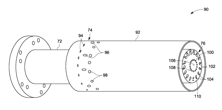
[0026] FIG. 3 is a diagrammatical illustration of an exemplary
configuration 90 of
the combustor nozzle of FIG. 2 having premixed and diffusion operation
capability
with syngas fuel in accordance with aspects of the present technique. In the
illustrated
embodiment, a burner tube 92 is disposed about the combustor nozzle 72. The
first
fuel system 74 for introducing the hydrocarbon fuel or the syngas fuel for a
lean
premixed operation mode includes a plurality of injection orifices 94 disposed
on the
burner tube 92. Additionally, the first fuel system includes a plurality of
injection
orifices 96 disposed on a plurality of swozzle vanes (not shown) for
introducing the
hydrocarbon fuel or the syngas fuel within the combustor nozzle 72. In
operation, the
plurality of swozzle vanes are configured to provide a swirling motion to
incoming air
and to introduce the syngas fuel or the hydrocarbon fuel within the combustor
nozzle
for a premixed mode with syngas or hydrocarbon. The swozzle vanes will be
described in a greater detail below with reference to FIG. 4.
[0027] In this embodiment, the combustor nozzle 90 also includes an
additional set
of orifices 98 disposed on the burner tube 92 for introducing the syngas fuel
within
the nozzle 72 for the premixed syngas mode of operation. It should be noted
that the
additional set of orifices 98 are provided to supply volumetric flow of syngas
fuel
required for the premixed syngas mode of operation. The premixing residence
time of
the combustor nozzle is between about 0.1 ms to 10 ms. A plurality of patterns
of the
orifices 98 may be envisaged to facilitate the introduction of the syngas fuel
within
the nozzle 72. The pattern and shape of the orifices is selected to maximize
jet
penetration into each quadrant of the vane sector area thereby increasing the
fuel-air
7
CA 02665319 2009-04-02
WO 2008/057685
PCT/US2007/080519
homogeneity. In certain embodiments, the orifices 98 are equally spaced across
the
vane sector and are sized to balance the mass flow into each half of the vane
sector.
[0028] In addition, the nozzle 90 includes the second fuel system 76 for
introducing the syngas fuel, and/or hydrocarbon fuel and diluents within the
combustion chamber 78 to enable diffusion combustion of the syngas fuel within
the
combustion chamber 78. In the illustrated embodiment, the second fuel system
76
includes a diffusion nozzle tip that includes injection orifices 100, 102 and
104
forming inner, outer and middle co-annular passages 106, 108 and 110 for
introducing
the syngas fuel, hydrocarbon fuel and diluents within the combustion chamber
78. In
this embodiment, the diluents include steam, nitrogen and carbon dioxide.
However,
certain other inert gases may be employed as the diluents. The combustor
nozzle 90
also includes a controller 80 (see FIG. 2) coupled to the first and second
fuel systems
74 and 76 for selecting a combustion mode based upon a fuel type, or a fuel
calorific
heating value of the fuel stream. Further, the controller is configured to
control the
flow through the injection orifices 100, 102 and 104 of the second fuel system
76
based upon a required volumetric flow of the syngas fuel.
[0029] FIG. 4 is a diagrammatical illustration of an exemplary
configuration 120
of the combustor nozzle 90 of FIG. 3 having swozzle fuel injection points in
accordance with aspects of the present technique. The combustor nozzle 120
includes
swozzle vanes 122 that are configured to provide a swirling motion to the
incoming
air. Further, the swozzle vanes 122 are configured to introduce the
hydrocarbon fuel
and the syngas fuel into the nozzle 120 through the swozzle fuel injection
points 124.
Typically, the swozzle vanes 122 are designed to maximize the fuel-air mixing
to
meet performance requirements such as flame holding and low emissions. In the
illustrated embodiment, the hydrocarbon fuel includes natural gas. In
operation,
natural gas, or the syngas fuel introduced through the swozzle vanes 122 is
mixed
with air in a location upstream of the combustion chamber 78 (see FIG. 2) to
generate
a premixed flame at lean conditions that are conducive for low emissions.
[0030] In certain embodiments, the injection of the hydrocarbon fuel or the
syngas
fuel through the plurality of injection orifices 96 takes place at one
location per side
8
CA 02665319 2009-04-02
WO 2008/057685
PCT/US2007/080519
of each swozzle vane 122. Further, the injection of the hydrocarbon fuel or
the
syngas fuel through the plurality of injection orifices 96 takes place at one
or more
injection points per swirler vane. The injection points may be located on one
or both
sides of the vane at different radial positions, and may have different
diameters. In
this exemplary embodiment, the injections points are located on the sides of
the
vanes. In certain other embodiments, the injection points may be located at
the trailing
edge. Advantageously, such injection of fuel through the injection orifices 94
and 96
enhances fuel jet penetration into each quadrant of each vane sector, thereby
facilitating the mixing within the combustor nozzle 120. It should be noted
that the
injection points 96 on the swozzle vanes 122 and the injection points 94 and
98 on the
burner tube 92 are coupled to individual fuel feed systems, thereby
facilitating control
of combustion dynamics in the system.
[0031] As will be appreciated by one skilled in the art the combustion
system 64 is
fired in a premixed configuration with natural gas when the coal gasified
syngas fuel
supply is interrupted or is required for alternative power plant uses.
Alternatively, the
combustion system 64 is fired in a premixed or a diffusion mode with syngas
fuel,
where the fuel is introduced within the nozzle 120 through the first or second
fuel
systems 74 or 76. In certain embodiments, the combustion system may be started
with natural gas in the second fuel system 76.
[0032] In this exemplary embodiment, the diffusion nozzle tip is designed
to
maximize the performance based upon the design of the swozzle vanes 122. In
particular, the tip geometry of the nozzle 120 may be optimized for the
airflow pattern
generated by the swozzle vanes 122. Moreover, the injection orifices 100, 102
and
104 are designed to handle a wide range of syngas fuels and accompanying
diluents
for low emission performance. It should be noted that the flow of syngas fuel,
hydrocarbon fuel and diluents through the injection orifices 100, 102 and 104
may be
controlled based upon a desired volumetric flow rate of the syngas fuel. For
example,
in the illustrated embodiment, the first passage 106 is configured to
introduce the
steam into the combustion chamber 78 of the combustor. Further, the second
passage
108 disposed around the first passage 106 is configured to introduce the
syngas fuel
and the third passage 110 disposed about the first and second passages 106 and
108 is
9
CA 02665319 2009-04-02
WO 2008/057685
PCT/US2007/080519
configured to introduce nitrogen within the combustion chamber of the
combustion
system. As will be appreciated by one skilled in the art, a plurality of
operational
modes for the first second and third passages 106, 108 and 110 may be
envisaged
based upon the fuel calorific value of the syngas fuel.
[0033] The first, second and third passages 106, 108 and 110 are designed
so that
the combustor nozzle 120 may be employed with either oxygen-enhanced or with
traditional gasification units. As will be appreciated by one skilled in the
art in the
traditional gasification units, steam from the gasification units may be
utilized as a
diluent to facilitate combustion. However, in the oxygen enhanced gasification
units
nitrogen from an air separation unit may be employed as an additional diluent
for
enhancing the overall plant efficiency.
[0034] In a present embodiment, the first, second and third passages 106,
108 and
110 are designed based upon a desired range of calorific heating values of the
fuel
produced from the coal gasification units. In this embodiment, the fuel
calorific value
of the syngas fuel is less than about 310 BTU/scf. In one embodiment, the fuel
calorific value of the syngas fuel is about between 100 BTU/scf to about 230
BTU/scf. For example, the passage for flowing syngas fuel may be designed to
account for introducing low heating value fuel that requires a large
volumetric flow
rate. Similarly, the passage for flowing diluents may be designed according to
higher
heating value fuel that require relatively greater diluent flow to meet
desired
performance levels.
[0035] In an exemplary embodiment, the first, second and third passages
106, 108
and 110 have a tangential injection angle of about 0 degrees to about 75
degrees and a
radial injection angle of about 0 degrees to about 75 degrees. In one
embodiment, the
second and third passages 108 and 110 have a tangential injection angle of
about 40
degrees and the first and second passages 108 and 110 have a radial injection
angle of
about 45 degrees. Further, in one embodiment, the flow of syngas fuel and
nitrogen
in the second and third passages 108 and 110 is counter swirled with respect
to the air
swirl generated by the vanes 122 to facilitate enhanced mixing, decreased
flame
length, reduced emissions and increased flame front pattern factors. Moreover,
as
CA 02665319 2009-04-02
WO 2008/057685
PCT/US2007/080519
described above, the controller 80 (see FIG. 2) may be coupled to the first,
second and
third passages 106, 108, 110 to control the flow of syngas fuel, hydrocarbon
fuel,
steam and nitrogen and CO2 within the passages 106, 108 and 110 based upon the
fuel calorific heating value of the syngas fuel. As described above,
individual fuel
plenums may be coupled to the first and second fuel systems 74 and 76 to
supply the
syngas or the hydrocarbon fuel during premixed and diffusion modes of
operation.
[0036] FIG. 5 is a sectional view 130 of the exemplary configuration of the
combustor nozzle 120 of FIG. 4 having individual fuel plenums for supplying
fuel to
the swozzle fuel injection points and burner tube fuel injection points in
accordance
with aspects of the present technique. As described before, the combustor
nozzle 130
includes first set of orifices 94 disposed on the burner tube 92 for
introducing the
syngas or hydrocarbon fuel within the nozzle 130. Further, the combustor
nozzle 130
includes second set of orifices 96 disposed on the swozzle vanes 122 (see
FIG.4) for
introducing the syngas or hydrocarbon fuel within the nozzle 130.
Additionally, the
combustor nozzle 130 includes third set of orifices 98 disposed on the burner
tube 92
for introducing the syngas fuel within the nozzle 130 to account for
additional
volumetric flow of the syngas fuel required for the premixed mode of
operation.
[0037] In the illustrated embodiment, the combustor nozzle 130 includes a
first
fuel plenum 132 configured to supply the hydrocarbon or syngas fuel to the
first set of
orifices 94 disposed on the burner tube 92 and a second fuel plenum 134
configured
to supply the hydrocarbon or syngas fuel to the second set of orifices 96
disposed on
the swozzle vanes 122. In addition, the combustor nozzle 130 includes a third
fuel
plenum 136 configured to supply the hydrocarbon or syngas fuel to the third
set of
orifices 98 disposed on the burner tube 72. The first, second and third fuel
plenums
132, 134 and 136 may be coupled to the controller 80 (see FIG.2) for
controlling the
supply of the fuel within the combustor nozzle 130. In this exemplary
embodiment,
the premixed mode of operation with the hydrocarbon fuel employs the first and
second set of orifices 94 and 96 for introducing the hydrocarbon fuel within
the
nozzle 130. Further, for the premixed mode of operation with syngas fuel the
third set
of orifices 98 are utilized for introducing the syngas fuel within the nozzle
130.
11
CA 02665319 2012-08-09
205480.-1
[0038] In certain embodiments, the combustor nozzle 130 is operated as a
stand-
alone configuration for the premixed mode of operation. In this exemplary
embodiment, the syngas mode of operation is controlled based upon the heating
value
of the fuel. For example, the first and second sets of orifices 94 and 96 will
be in use
at all times whereas the third set of orifices 98 will be employed based upon
the
heating value of the fuel. As described above, the combustor nozzle 130 may be
operated with the premixed hydrocarbon and syngas modes of operation along
with
the diffusion mode of operation with syngas. Alternately, the combustor nozzle
130
may be operated without the diffusion mode of operation with syngas as
described
below with reference to FIG. 6.
[0039] FIG. 6 is a diagrammatical illustration of another exemplary
configuration
140 of the combustor nozzle 72 of FIG. 2 having premixed operation capability
with
hydrocarbon and syngas fuel in accordance with aspects of the present
technique. As
illustrated, the combustor nozzle 140 includes the first, second and third
sets of
orifices 94, 96 and 98 for introducing the hydrocarbon or syngas fuels within
the
combustor nozzle 140 for premixed mode of operation. In addition, the nozzle
tip
includes a set of orifices 142 for introducing the hydrocarbon fuel for a
diffusion
mode during a light off condition.
[0040] FIG. 7 is a diagrammatical illustration of an exemplary
configuration 150 of
the combustor nozzle 140 of FIG. 6 having swozzle and centerbody fuel
injection
points in accordance with aspects of the present technique. In this exemplary
embodiment, the combustor nozzle 150 includes the swozzle injection points 96.
In
addition, the nozzle 150 includes a first set of orifices 152 disposed on the
centerbody
for introducing the hydrocarbon or syngas fuel within the nozzle 150 for
premixed
mode of operation. In addition, the nozzle includes a second set of orifices
154 for
introducing the syngas fuel to account for any additional volumetric flow
required
during premixed syngas mode of operation. Again, the first and second set of
orifices
152 and 154 may be coupled to individual fuel plenums as will be described
below
with reference to FIG. 8. Beneficially, this mode of operation provides
greater
flexibility of operation since more or less injection points may be used for
fuel
injection depending upon the heating value of the fuel. Further, the numerous
number
12
CA 02665319 2009-04-02
WO 2008/057685
PCT/US2007/080519
of injection points allows for greater fuel flexibility of the combustor by
accounting
for large variations in flow rates that occur over the range of syngas fuels.
[0041] FIG. 8 is a sectional view 160 of the exemplary configuration of the
combustor nozzle 150 of FIG. 7 having individual fuel plenums for supplying
fuel to
the swozzle and centerbody fuel injection points in accordance with aspects of
the
present technique. As illustrated, the combustor nozzle 160 includes the
first, second
and third sets of orifices 94, 96 and 98 for introducing the hydrocarbon or
the syngas
fuel within the nozzle 160 during a premixed mode of operation. In addition,
the
nozzle 160 includes the orifices 152 and 154 disposed on the centerbody for
introducing the hydrocarbon or syngas fuel within the nozzle 150 for premixed
mode
of operation. As described before, the first, second and third sets of
orifices are
coupled to the fuel plenums 132, 134 and 136 for supplying the fuel. In this
exemplary embodiment, the nozzle 160 also includes fuel plenums 162 and 164
configured to supply the hydrocarbon or syngas fuel to the orifices 152 and
154
respectively. Again, each of the fuel plenums 162 and 164 may be coupled to
the
controller 80 (see FIG.2) for controlling the supply of the fuel to the
orifices 152 and
154.
[0042] The various aspects of the method described hereinabove have utility
in
different applications such as combustion systems employed in IGCC systems. As
noted above, the fuel-flexible combustion system works with a variety of fuels
while
having reduced emissions. Further, the combustion system has sustained low
emission firing with a backup fuel and is adaptable to different power plant
configurations while maintaining the overall power plant efficiency. In
particular, the
present technique employs a combustor nozzle that operates with natural gas
and a
wide range of syngas fuels by switching between lean premixed and diffusion
combustion modes based upon a desired volumetric flow rate of the fuel
feedstock.
[0043] Advantageously, the premixed combustion mode facilitates the
operation of
the combustion system without requiring diluents for meeting the emission
requirements thereby reducing the fuel consumption of the combustion system.
Further, the premixed combustion mode allows the byproducts of an air
separation
13
CA 02665319 2012-08-09
205480-1
unit for oxygen enhanced gasifiers and steam from steam turbine to be utilized
more
efficiently in other plant processes such as chemical production, after-
treatment,
combined cycle power generation and so forth. Thus, the combustion system has
significantly enhanced fuel flexibility while maintaining reduced emissions
and may
be operated with different power plant configurations while maintaining the
overall
power plant efficiency.
[0044] While
only certain features of the invention have been illustrated and
described herein, many modifications and changes that fall within the scope of
the
present invention described herein will occur to those skilled in the art.
14