Note: Descriptions are shown in the official language in which they were submitted.
CA 02665433 2009-05-06
UCON 1000-1
HANDS-FREE FUELING CONTROL SYSTEM
Inventor: Byron C. Cheung
BACKGROUND OF THE INVENTION
[0001] The invention relates to fuel management systems, such as those used to
authorize refueling of fleet vehicles.
[0002] Many organizations have fleets of vehicles, and have a refueling
station for
these vehicles on their property. In order to prevent fuel theft by
unauthorized vehicles, or
merely in order to keep track of fuel usage by individual vehicles, the
refueling stations are
often designed to require the user or vehicle to establish their authority to
receive fuel from
the station, before the station site control system will turn on the fuel
dispenser. A variety of
different mechanisms have been employed to allow the user to establish such
authorization. In
various systems authorization is accomplished by the user (often the vehicle's
driver) inserting
an identification card into a reader associated with the particular desired
dispenser, or
bringing an RFID tag into proximity with a tag reader, or even entering a code
on a keyboard
at the fueling island. Two problems with manual keyboard entry systems are
that the user may
have to remember long codes, and entry of such codes can be subject to error.
A problem with
card authorization systems is that cards can be lost, stolen or forged.
[0003] In one prior art system that avoids the above problems, a transponder
module
is mounted on or in the vehicle, and is connected to an antenna ring which
encircles the inlet
of the vehicle's fuel tank. Another antenna wire is mounted on each dispenser
nozzle, and
connected to a base station. When the user inserts the nozzle into the
vehicle's fuel inlet, the
transponder module in the vehicle transmits a vehicle identification code via
the two antennas
to the base station. The base station determines the vehicle's authority to
receive fuel, and then
turns on the fuel dispenser associated with nozzle from which the vehicle
identification code
was received.
[0004] While this system works well, the antenna wire can be difficult to
install on the
nozzles and to wire to the base station. The antenna and connection wire are
also subject to
breakage, and can be difficult to maintain. The antenna ring on the vehicle's
fuel inlet also can
be difficult to install and maintain, because it has to be wired to the
transponder module,
{00160568.DOC } I
CA 02665433 2009-05-06
UCON 1000-1
i y
which in turn has to be wired to the vehicle's battery. Depending on where the
transponder
module is located in or on the vehicle, either the antenna wires or the
battery wires or both
must be routed through hidden or protected areas of the vehicle exterior and
interior, which is
time consuming at best. For some vehicles, the fuel inlet also lacks
sufficient clearance for the
antenna ring to fit around it.
[0005] Another prior art system which avoids some of these problems uses an
RFID
tag embedded on a plastic or fiberglass ring encircling the nose of the
nozzle, instead of an
antenna wired to the base station. The antenna ring on the inlet of the
vehicle's fuel tank
remains, but is operated differently. In this system, when the user inserts
the nozzle into the
vehicle's fuel inlet, the transponder in the vehicle reads the nozzle ID from
the RFID tag via
the antenna ring at the fuel inlet. The transponder then transmits the nozzle
ID as well as a
vehicle ID wirelessly to the base station. The base station then determines
the vehicle's
authority to receive fuel, and turns on the fuel dispenser associated with the
nozzle on which
the indicated RFID tag was mounted.
[0006] This system avoids the difficulty with installing and maintaining a
nozzle
antenna and connection wire, but other problems arise instead. In particular,
maintenance
personnel repairing or replacing the nozzles sometimes neglect to replace the
RFID ring on
the nozzle after repair, or sometimes even fail to notice its presence on a
nozzle being
replaced. Both of these issues will cause the vehicle transponder to fail to
receive a nozzle ID,
so the dispenser will never turn on. In addition, the RFID rings on the
nozzles can crack when
the nozzle is dropped onto the pavement, and they also can crack at low
ambient
temperatures, which increases maintenance problems in colder climates.
Furthermore,
installation of the equipment on the vehicle remains just as difficult.
[0007] In light of the above, an opportunity arises to provide an improved
system for
controlling the dispensing of fuel to authorized vehicles.
SUMMARY
[0008] Roughly described, a fueling control system includes a nozzle module
for use
with a particular fuel dispensing nozzle, a vehicle module for use with a
particular fuel tank
inlet, and a site controller. The nozzle module, in response to predefined
user activation
(00160568.DOC it 2
CA 02665433 2009-05-06
UCON 1000-1
behavior such as removal of the nozzle from an on-hook position and insertion
into the inlet
of a fuel tank, awakens from a low power mode to an active mode, and
wirelessly transmits a
wake-up signal and an identification of the particular nozzle. The vehicle
module, in response
to detection of the wake-up signal, awakens from a low power mode to an active
mode,
detects the transmitted nozzle identification, and wirelessly requests
authorization for the
particular nozzle to dispense fuel. The site controller, in response to
detection of the nozzle
identification, authorizes dispensing of fuel through the particular nozzle.
[0009] The above summary is provided in order to convey a basic understanding
of
some aspects of the invention. The summary is not intended to identify key or
critical
elements of the invention or to delineate the scope of the invention. Its sole
purpose is to
present some concepts of the invention in a simplified form as a prelude to
the more detailed
description that is presented later. Particular aspects of the invention are
described in the
claims, specification and drawings.
BRIEF DESCRIPTION OF THE DRAWINGS
[0010] The invention will be described with respect to particular embodiments
thereof, and reference will be made to the drawings, in which:
[0011] Fig. 1 illustrates a refueling station 100 that incorporates features
of the
invention.
[0012] Fig. 2 is a schematic drawing illustrating interconnections among some
components of Fig. 1.
[0013] Fig. 3 is a drawing of a nozzle, mounted in its "on-hook" position.
[0014] Fig. 4 is a drawing of the fuel inlet area of a vehicle.
[0015] Fig. 5 is a flow diagram for illustrating the overall operation of the
system.
[0016] Fig. 6 is a diagram of a protocol by which a vehicle module requests
authorization for a particular nozzle to dispense fuel.
[0017] Fig. 7 is a block diagram of a nozzle module.
[0018] Fig. 8 is a schematic diagram of parts of the nozzle module 314,
showing
particular detail in the power control section of Fig. 7.
[0019] Fig. 9 illustrates a nozzle as inserted into the inlet of a vehicle
fuel tank.
[0020] Fig. 10 is a flow chart of functions performed by the nozzle module of
Fig. 7.
{00160568.DOC } 3
CA 02665433 2009-05-06
UCON 1000-1
[0021] Fig. 11 is a block diagram of a vehicle module.
[0022] Fig. 12 is a flow chart of functions performed by the vehicle module of
Fig. 11.
[0023] Fig. 13 is a flow chart of functions performed by the site controller
of Fig. 2.
[0024] Fig. 14 is a schematic diagram of parts of the vehicle module 414,
showing
particular detail in the power control section of Fig. 11.
DETAILED DESCRIPTION
[0025] The following detailed description is made with reference to the
figures.
Preferred embodiments are described to illustrate the present invention, not
to limit its scope,
which is defined by the claims. Those of ordinary skill in the art will
recognize a variety of
equivalent variations on the description that follows.
[0026] Fig. 1 illustrates a refueling station 100 that incorporates features
of the
invention. It comprises an administration building 110 and one or more fuel
islands 112 (only
one of which is shown). Two fuel dispensers 116 are located on the fuel island
112. While the
fuel dispensed by these dispensers is gasoline, it will be appreciated that in
other
embodiments the fuel can be diesel, propane, CNG, etc. A pillar 118 is also
located on the
fuel island 112, on which is mounted an individual polling unit 120 for the
fuel island 112,
and a fuel island controller 122. A master interrogator 124 is located within
wireless
communication distance with all the fuel islands, and a site computer 126,
which may be a
conventional personal computer programmed as described herein, is housed in
the
administration building 110. Each dispenser 116 includes one or more fuel
nozzles 128 (only
one of which is shown on each dispenser), and on each such nozzle is mounted a
respective
nozzle module (not shown in Fig. 1). A vehicle 130 is shown parked at one of
the dispensers
116, ready for fueling. The vehicle 130 has a fuel tank inlet 132 on the side
of the vehicle
facing the dispenser 116. (As used herein, the terms "fueling" and "refueling"
are
interchangeable.)
[0027] The site computer 126, the master interrogator 124, the fuel island
controllers
122 and the individual polling units 120 all operate cooperatively to perform
the functions
described herein for controlling the dispensing of fuel from the dispensers
116. Collectively
they are referred to herein as the site controller 210. Some of these
components also perform
{00160568.DOC } 4 .
CA 02665433 2009-05-06
UCON 1000-1
other functions not related to the present discussion. Fig. 2 is a schematic
drawing illustrating
some of interconnections among these components. As shown, the site computer
126 is
connected to the master interrogator 124 and to each of the fuel island
controllers 122. Each
of the fuel island controllers 122 is in turn connected to all of the fuel
dispensers 116 on its
fuel island, and to one of the individual polling units 120. In operation, the
master interrogator
124 and the individual polling units 120 are involved in communicating
wirelessly with the
vehicle modules as described hereinafter. When the site computer 126
authorizes the
dispensing of fuel through a particular nozzle 128, it so notifies the
appropriate fuel island
controller 122, which in turn authorizes the appropriate dispenser 116 to turn
on appropriate
nozzle 128.
[0028] The particular arrangement of components shown in Fig. 2 depict only
one
arrangement of equipment for performing the functions described herein for
controlling the
dispensing of fuel at the site 100. Numerous other arrangements and divisions
of functions
among components are possible as well. The term "site controller" is intended
herein to
encompass whatever equipment is involved in a particular installation for
performing the
functions described herein for the site controller. It is to be noted that in
some installations,
one or more of the components may be located off-premises. Additionally,
although the
fueling site of Fig. 1 itself is shown as a stationary building, in another
embodiment it can be
mobile, and installed for example on a fuel tanker truck.
[0029] Fig. 3 is a drawing of one of the nozzles 128, mounted in its "on-hook"
position on one of the dispensers 116. The "on-hook" position as used herein
means its
position when stowed, and in some installations it might be on a hook, for
example, rather
than on a dispenser. The nozzle has an angle when on-hook, which may be
defined by any of
a number of reference surfaces or features on the nozzle. For convenience, as
used herein, the
"angle" of a nozzle at any point in time is the angle of its centerline at the
longitudinal flow
position where fuel exits the nozzle, measured relative to the vertical. In
the view of Fig. 3,
the centerline is denoted 310, and the angle it makes with the vertical is
denoted 312.
[0030] Mounted on the nozzle handle is a nozzle module 314, described in more
detail
hereinafter. Preferably it is protected by a rubber boot that encases the
nozzle handle, but that
is not required in all embodiments. If provided, the boot preferably includes
a recess
specifically to accommodate the nozzle module 314. The presence of the nozzle
module 314
{00160568.DOC } 5
CA 02665433 2009-05-06
UCON 1000-1
therefore is not hidden from maintenance personnel, and so is less likely to
be neglected after
repair or replacement of the nozzle 128. Additionally, the rubber of the boot
is preferably
flexible enough that the absence of a nozzle module inside the boot can be
easily noticed
because the boot will look limp.
[0031] The nozzle module 314 preferably uses a tilt switch to trigger
activation as
described hereinafter, but if a different activation trigger is provided, then
the nozzle module
314 can be located somewhere else instead of on the nozzle. The nozzle module
314 is located
at the fueling site rather than on the vehicle, and each nozzle module 314 is
associated with a
particular corresponding fueling nozzle. In an installation in which nozzles
are not enabled
individually, then each nozzle module 314 can be associated with a
corresponding group of
fueling nozzles 128 that are enabled together.
[0032] Fig. 4 is a drawing of the fuel inlet area of the vehicle 130. On the
example
vehicle shown, the fuel inlet 132 is protected by a fuel door 410, shown in
the figure in its
open position. Mounted near the fuel inlet 132, on the inside of the fuel door
410 in the
example shown, is a vehicle module 414, described in more detail hereinafter.
Note that the
system described. herein can also be used to fuel standalone fuel tanks, which
need not
necessarily be associated with vehicles. In such a case the vehicle module 414
can be
mounted on the fuel tank near its fuel inlet, or can even be carried
separately by the user and
brought into proximity with the nozzle module 314 from which fuel is desired.
[0033] Both the nozzle module 314 and the vehicle module 414 are battery
operated,
and both communicate with other components of the system wirelessly. Thus
neither needs be
wired to any other component, thereby greatly simplifying installation and
maintenance.
Overall System Operation
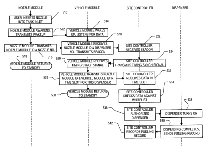
[0034] Fig. 5 is a flow diagram which illustrates the overall operation of the
system.
Four main components are involved in the operation: the nozzle module 314 for
the nozzle
associated with the dispenser from which the user desires fuel; the vehicle
module 414 on the
vehicle or fuel tank into which the fuel is to be dispensed; the site
controller 210; and the
dispenser 116. It is to be noted that some of the functions ascribed herein to
the dispenser 116
might actually be performed by the fuel island controller 122, so as used
herein, the term
{00160568.DOC } 6
CA 02665433 2009-05-06
UCON 1000-1
"dispenser" is considered to include those portions of other components not
physically on the
pump itself that are involved in the performance of such functions.
[0035] Referring to Fig. 5, both the nozzle module 314 and the vehicle module
316
begin in standby modes. In this mode both modules draw very little power if
any from their
respective batteries, thereby preserving battery life.
[0036] In step 510, the user inserts the nozzle 128 into the tank inlet. By
means
described below, this action causes the nozzle module 314 to awaken and to
transmit a wake-
up signal wirelessly to the vehicle module 414 (step 512). In step 514, the
vehicle module 414
awakens and listens for data from the nozzle module 314. In one embodiment,
the data is sent
separately and subsequently to the wake-up signal. In a preferred embodiment,
however, the
data is sent as part of the wake-up signal, and is repeated a number of times
to permit the
vehicle module 414 sufficient time to awaken and decode it. In Fig. 5 the data
is shown
transmitted by the nozzle module 314 separately from the wake-up signal, in
step 516, but it
will be understood that step 516 may simply be a re-transmission of the wake-
up signal
transmitted in step 512. After transmitting the data, in step 518, the nozzle
module 314 returns
promptly to standby mode without transmitting anything further. The entire
operation of the
nozzle module 314 can complete in only a few seconds, thereby minimizing the
draw of
power from the battery.
[0037] Note that the communication between the nozzle module 314 and the
vehicle
module 414 is unidirectional. No acknowledgement signal, for example, is
transmitted from
the vehicle module 414 back to the nozzle module 314 to indicate either that
it has awaken
and is ready to receive data, or that it has successfully received data. While
either or both of
such acknowledgment signals can be included in a different embodiment, their
absence in the
embodiment of Fig. 5 permits a simpler and less costly design of the nozzle
module 314 since
it does not require any components for receiving and decoding any incoming
radio signals.
The vehicle module 414 can also be made simpler and less costly, since the
transceiver used
for communicating with the site controller 210 differs from the one used for
communicating
with the nozzle module 314, and the latter can be a receiver only.
[0038] While an acknowledgement for handshaking between the two modules could
be implemented in order to notify the nozzle module 314 to re-transmit should
the vehicle
module 414 fail to awaken after the first transmission, the first transmission
tends to succeed
{00160568.DOC 1 7
CA 02665433 2009-05-06
UCON 1000-1
the vast majority of times. Additionally, since the data transmitted by the
nozzle module 314
in step 516 is the same as the wake-up signal transmitted in step 512 in the
present
embodiment, the second transmission of this signal in step 516 can awaken the
vehicle
module 414 should the first transmission fail to do so. In that case the
vehicle module 414 will
obtain the data from the third transmission of the wake-up/data signal. Still
further, if all the
wake-up/data signal transmissions from the nozzle module 314 fail to awaken
the vehicle
module 414, then the nozzle will not dispense fuel and the user will
intuitively remove the
nozzle from the fuel tank inlet, tilting it up to approximately its on-hook
position before re-
inserting it into the inlet. This will reset the nozzle module 314 and cause
it to transmit the
wake-up/data signal again.
[00391 The data sent by the nozzle module 314 includes an identification of
the nozzle
with which it is associated (for example a number ranging from 1-16).
Preferably it also
includes an identification of the nozzle module 314 itself, though some
embodiments can omit
that feature. The data is received by the vehicle module 414 in step 520, and
in response to
receiving the data, it transmits a beacon signal to the site controller 210.
The beacon signal is
received by the site controller 210 in step 522. The beacon signal is the same
signal as is sent
by all vehicle modules after receipt of data from a nozzle module 314, and
serves the function
of notifying the site controller 210 that at least one vehicle module at the
site is ready to
transmit data to the site controller 210. The beacon signal does not indicate
which vehicle
module is ready to transmit.
[00401 Fig. 6 is a diagram of the protocol according to which the vehicle
modules 414
transmit data to the site controller to request authorization for a particular
nozzle to dispense
fuel. During time 610, the site controller 210 detects the beacon signal. In
response thereto,
during time 612, the site controller 210 transmits a synchronization signal,
which indicates to
all the vehicle modules 414 the start of M repetitions (cycles) 614-1 through
614-M
(collectively 614) of a sequence of N time slots each. The diagram shows an
exploded view of
one cycle 614-1 for illustrating the time slots 616-1 through 616-N
(collectively 616). Thus,
each of the N time slots repeats M times. In an embodiment, M can be 4 and N
can be 16.
Each time slot occupies, for example, on the order of 75-100 ms. Each time
slot in a given
cycle is allocated to a respective one of the nozzles 128; thus, the system
can accommodate up
to N nozzles 128. Stated another way, each nozzle 128 (or group of nozzles, if
they are to be
{00160568.DOC } 8
CA 02665433 2009-05-06
UCON 1000-1
authorized only as a group) that is present and available for dispensing fuel
at the site, has an
associated and dedicated one of the time slots 616 allocated to it.
[0041] Returning to Fig. 5, therefore, after the site controller 210 detects
the beacon
signal in step 522, it wirelessly transmits the timing synchronization signal
612 (step 524).
The vehicle module 414 detects the timing synchronization signal in step 526,
and in response
thereto, in step 528, it transmits its data during each repetition of the time
slot associated with
the nozzle ID that it received from the nozzle module 314 in step 420. The
vehicle module
414 then returns to standby mode without making any further transmissions
(step 530), again
minimizing battery usage. The data sent by the vehicle module 414 is received
by the site
controller 210 in step 532, and from the number of the time slot in which the
data was
received, the site controller 210 knows which nozzle is the subject of the
authorization
request.
[0042] Preferably the data transmitted by the vehicle module 414 in step 528
includes
the nozzle module ID which the vehicle module 414 had received from the nozzle
module 314
in step 520, and in step 534, the site controller 210 checks the nozzle module
ID against a
whitelist database. Preferably the data also includes an identification of the
vehicle module
414 as well, and the site controller 210 also checks the vehicle module ID
against a whitelist
database in step 534. As used herein, the whitelist checks in step 534 are
said to "verify the
authority" of the nozzle module 314 to authorize the dispensing of fuel
through its associated
nozzle 128, and to "verify the authority" of vehicle module 414 to authorize
the dispensing of
fuel into its associated fuel tank inlet 132. Verification of authority, as
used herein, is different
from merely verifying the module ID, which could mean checking merely that it
is the
module that is attached to the particular nozzle. Additionally, whereas the
site controller in
step 534 verifies the authority of modules 314 and 414 to authorize the
dispensing of fuel by
comparing their IDs to respective whitelists, it will be understood that
numerous other
verification mechanisms can be used instead in different embodiments. For
example, the IDs
could be checked against blacklists, or even merely verified against some
mathematical ID
validity criteria. Other variations will be apparent to the reader.
[0043] In step 536, assuming authority has been verified in step 534, the site
controller
210 signals the dispenser for nozzle 128 to turn on the nozzle (or group of
nozzles) associated
with the time slot 616 in which the data was received in step 532. This
authorization is
{00160568.DOC 1 9
CA 02665433 2009-05-06
UCON 1000-1
typically performed via a wired connection from the site computer 126 to the
appropriate fuel
island controller 122, but could be performed wirelessly in a different
embodiment. In step
532 the dispenser turns on. When dispensing completes, typically indicated by
return of the
nozzle 128 to the on-hook position, this is sensed by the dispenser 116. In
step 540, the
dispenser transmits a fueling record to the site controller 210. The site
controller receives it in
step 542 and records it in a database.
Nozzle Module
[0044] Fig. 7 is a block diagram of an embodiment of the nozzle module 314. It
includes a battery 710 connected to a power control section 712, which
forwards power to a
transmit section 714 via a power line 722. The battery 710 is dedicated to the
nozzle module
314 and avoids any need for a wired connection to an external power source.
The transmit
section 714 includes a microcontroller 716 having one output that drives an
Amplitude Shift
Keying (ASK) modulator 718, the output of which drives a transmit coil 720.
The
microcontroller 716 also has a shut-down output 724 by which it signals the
power control
section 712 to return the nozzle module 314 to standby mode. As mentioned, the
nozzle
module 314 remains in a low power standby mode until it is awakened by some
predefined
user behavior, after which it transmit its data (steps 512 and 516) and
returns to standby
mode. Since the functions of the nozzle module 314 do not include receiving
any transmission
from outside the nozzle module 314, it has no receiver section. (In an
embodiment a receiver
section can be provided but not used.)
[0045] Fig. 8 is a schematic diagram of parts of the nozzle module 314,
showing
particular detail in the power control section 712. The power control section
712 has a battery
power input 810 connected to the battery 710, which is bypassed by a bypass
capacitor 812.
The battery power input 810 is connected to the power input terminal of a
power switch 814,
which may for example be a model MAX891L available from Maxim Integrated
Products,
Sunnyvale, CA. The power output terminal of the power switch 814 is bypassed
to ground by
a capacitor 816 and also by a resistor 818, and forms the power output lead
722 of the power
control section 712.
[0046] The battery power input 810 of the power control section 712 is also
connected
via a first tilt switch 820 to one terminal of a capacitor 822, the other
terminal of which is
{00160568.DOC } 10
CA 02665433 2009-05-06
UCON 1000-1
connected via a resistor 824 to the anode of a diode 826. The cathode of the
diode 826 is
connected to the base of an NPN transistor 828. The emitter of transistor 828
is connected to
ground, and the collector is connected through a pull-up resistor 830 to the
battery power
input 810. The collector of transistor 828 is also connected to an active low
control
(ON-/OFF) input of the power switch 814. Power switch 814 also has a ground
terminal
connected to ground.
[0047] The power output lead 722 is also connected via a resistor 832 to the
anode of
a second diode 834, the cathode of which is connected. to the base of
transistor 828. The base
of transistor 828 is also connected through a pull-down resistor 836 to
ground. In addition, the
series combination of a resistor 838 and a second tilt switch 840 is connected
across capacitor
822. A third tilt switch 841 is connected between ground and the junction
between resistor
832 and the anode of diode 834.
[0048] The shut-down output 724 of the transmit section 714 is connected via a
resistor 842 to the base of an NPN transistor 844, the emitter of which is
connected to ground
and the collector of which is connected to the base of transistor 828.
[0049] Tilt switch 820 senses the angle of the board on which it is mounted,
and hence
senses the angle of the nozzle 128. When the nozzle 128 is in its on-hook
position as shown in
Fig. 3, and the nozzle 128 makes an angle 312 with the vertical (Fig. 3), tilt
switch 820 is
open (non-conducting). Fig. 9 illustrates the nozzle 128 as inserted into the
inlet 132 of the
fuel tank of vehicle 130. In this position, the nozzle makes an angle 910 with
the vertical,
which is on the order of 60 degrees greater than the angle 312. There is
another position (not
shown) in which the nozzle is often used, for example where the nozzle is
inserted into the
fuel tank for a generator on a truck. That angle is approximately 90 degrees
greater than the
angle 312. It is desired that the nozzle module transmitter section 714 turn
on when the user
tilts the nozzle for inserting into fuel inlet of either a vehicle or a
generator tank, so the tilt
switch 820 is designed to close (conduct) when the nozzle tilt reaches some
angle which is
sufficiently greater than the on-hook nozzle angle 312 to avoid triggering by
accident, yet not
so great that it exceeds the normal angle of the nozzle when inserted into the
fuel inlet. Any
angle greater than approximately 45 degrees would be appropriate for this
purpose, and in the
embodiment of Fig. 8, the tilt switch 820 is designed to close when the nozzle
tilt angle
exceeds the on-hook nozzle angle 312 by about 60 degrees. It is also desirable
that the nozzle
{00160568.DOC } 11
CA 02665433 2009-05-06
UCON 1000-1
module transmitter section 714 not be triggered if the nozzle tilt exceeds
about 90 degrees
more than the on-hook tilt angle 312, because that angle also indicates that
the nozzle is not
being used for fueling and should not be turned on. Thus tilt switch 820 is
also designed to
open when the nozzle tilt angle exceeds the on-hook nozzle angle 312 by about
90 degrees.
Tilt switches which can be ordered to operate at the angles described herein
include the SQ-
SEN-390 series available from SignalQuest, Inc., Lebanon, NH. Tilt switches
840 and 841 are
both designed to switch at the same tilt angles as switch 820, but in a
complimentary manner.
That is, tilt switches 840 and 841 close when tilt switch 820 opens, and. open
when tilt switch
820 closes.
[0050] In operation, when the nozzle 128 is on-hook, tilt switch 820 is open,
tilt
switch 841 is closed, and power switch 814 is off. Thus no current flows into
the base of
transistor 828 through either of the diodes 826 and 834, and pull-up resistor
830 pulls the
voltage on the control input of power switch 814 up to its inactive level.
Power switch 814
therefore remains off, and no power is supplied on line 722 to the transmit
section 714. When
the nozzle 128 is removed and tilted for inserting into a fuel tank inlet,
tilt switch 820 closes
and tilt switches 840 and 841 open. Battery current therefore flows through
the tilt switch 820,
capacitor 822, resistor 824 and diode 826 to the base of transistor 828, which
pulls down the
control input of power switch 814 to its active level, transferring power onto
the power supply
line 722 to the transmit section 714. Capacitor 822 eventually charges and
current ceases to
flow through it to the base of transistor 828, but power switch 814 is latched
in its on mode
since current is flowing from the power lead 722 through resistor 832 and
diode 834 into the
base of transistor 828. Tilt switch 841 is open when the nozzle is in the
fueling position, so it
does not divert any of the current flowing through resistor 832.
[0051] After the transmit section 714 completes its work it asserts the shut-
down
signal on line 724, causing transistor 844 to pull down the voltage on the
base of transistor
828. This turns off transistor 828, which "breaks the latching circuit" by
allowing the voltage
on the control input of power switch 814 to rise to the inactive level and
turning it off. Thus
battery power is prevented from reaching the power output lead 722 and
transmit section 714
shuts down.
[0052] At some further time, the nozzle 128 is removed from the fuel tank
inlet and
replaced on-hook. This causes tilt switch 840 to close, thereby discharging
capacitor 822 in
{00160568.DOC } 12
CA 02665433 2009-05-06
UCON 1000-1
preparation for the next activation. It also causes tilt switch 820 to open,
thereby preventing
any conduction of battery power through the tilt switch 840 or the newly
discharged capacitor
822 from re-triggering the power switch 814 to turn on. It also causes tilt
switch 841 to close,
once again ensuring that the latching circuit remains broken. The nozzle
module 314 remains
in this low power mode until the nozzle 128 is again removed from the on-hook
position and
tilted to insert into a fuel tank inlet.
[0053] Note that the microcomputer 716 in the transmit section 714 is also
programmed with a watchdog timer that automatically asserts the shut-down
signal on line
724 after a predetermined number of seconds, should the microcomputer 716 fail
for some
reason to do so in the normal course.
[0054] With the above discussion as a foundation, Fig. 10 is a flow chart of
the main
functions performed by the nozzle module 314. As with all flowcharts herein,
it will be
appreciated that many of the steps can be combined, performed in parallel or
performed in a
different sequence without affecting the functions achieved. In some cases a
re-arrangement
of steps will achieve the same results only if certain other changes are made
as well, and in
other cases a re-arrangement of steps will achieve the same results only if
certain conditions
are satisfied. In step 1010, the nozzle module 314 is in standby mode. Standby
mode is a low
power mode which draws significantly less power from the battery 710 than
active mode.
Upon tilt switch activation, in step 1012, the power control section awakens
the transmit
section 714 to its active mode, as described above with respect to Fig. 8. The
transmit section
714 in step 1014 then transmits the nozzle number and nozzle module ID as
programmed into
the nozzle module 314 previously, some number of times P, as described above
with respect
to Fig. 5. P may be four, for example. Then, in step 1016, the transmit
section 714 asserts the
shut-down signal on line 724, to cause the nozzle module 314 to return to
standby mode (step
1010).
[0055] Note that while tilt switch activation as described herein is preferred
for
triggering activation of the nozzle module 314, other mechanisms can be used
instead in
different embodiments. For example, the tilt switch can be replaced by an
accelerometer, or
by a vehicle proximity detector for detecting arrival of the vehicle to be
fueled, or even by a
manually operated push-button if desired.
{00160568.DOC } 13
CA 02665433 2009-05-06
UCON 1000-1
Vehicle Module
[0056] Fig. 11 is a block diagram of the vehicle module 414. Like the nozzle
module
314, vehicle module 414 includes a battery 1110 supplying power to a power
control section
1112 which, when the vehicle module 414 is not in standby mode, supplies the
power to a
transceiver section 1114 via power line 1123. The battery 1110 is dedicated to
the vehicle
module 414 and avoids any need for a wired connection to the vehicle's power
system. The
transceiver section 1114 in the vehicle module 414 includes a microcontroller
1116 in
communication with an RF transceiver 1118 for communicating wirelessly with
the site
controller 210. The RF transceiver 1118 transmits with a range of at least
about 50 feet, since
it must reach all the way to the master interrogator 124. This is as
distinguished from the ASK
transmitter in the nozzle module 314, whose range is limited to about 18
inches, in order to
avoid awakening the vehicle module of a different vehicle that might be parked
at an adjacent
dispenser. The transceiver section 1114 also includes an ASK demodulator 1120
connected to
a pickup coil 1122, for recovering the data transmitted by the nozzle module
314. The ASK
demodulator 1120 also has an output 1121 connected to the power control
section 1112 to
provide the wake-up signal, and another output 1119 to provide received data
to the
microcontroller 1116. Like the nozzle module 314, the microcontroller 1116
also has a shut-
down output 1124 connected to the power control section 1112 to signal the
latter to return
the vehicle module 414 to standby mode when its operation is complete.
Microcontroller 1116
also has a demodulator reset output 1117 connected to the ASK demodulator
1120, by which
it resets the demodulator 1120 at the same time it signals the power control
section 1112 to
return to standby mode.
[0057] The power control section 1112 is similar to the power control section
712 in
the nozzle module 314, with a power switch in a latching circuit that latches
power on to the
transceiver section 1114 until the transceiver section 1114 asserts a shut-
down signal, which
operates to break the latching circuit. One significant difference is that the
power control
section 1112 is triggered to its active mode by an appropriate signal (the
wake-up signal from
the nozzle module 314) received by the pickup coil 1122, rather than by a tilt
switch.
[0058] Fig. 14 is a schematic diagram of parts of the vehicle module 414,
showing
particular detail in the power control section 1112 (Fig. 11). The power
control section 1112
has a battery power line input 1410 connected to the battery 1110, which is
bypassed by a
{00160568.DOC } 14
.............. .
CA 02665433 2009-05-06
UCON 1000-1
bypass capacitor 1412. The battery power input 1410 is connected to the power
input terminal
of a power switch 1414, which as for the nozzle module, may for example be a
model
MAX891L from Maxim Integrated Products. The power output terminal of the power
switch
1414 is bypassed to ground by a capacitor 1416 and also by a resistor 1418,
and is then
provided to the input of a step-up voltage regulator 1415. The output of
regulator 1415 forms
the power output lead 1123 of the power control section 1112.
[0059] The battery power input 1410 of the power control section 1112 is also
connected to the power supply input of ASK demodulator 1120. ASK demodulator
1121 has a
wakeup signal output 1121 connected via a resistor to the collector of an NPN
transistor 1428.
The collector of the transistor 1428 is also connected through a pull-up
resistor 1430 to the
battery power input 1410, and the emitter of transistor 1428 is connected to
ground. The
collector of transistor 1428 is also connected to an active low control (ON-
/OFF) input of the
power switch 1414. Power switch 1414 also has a ground terminal connected to
ground.
[0060] The power output lead of the power switch 1414 is also connected via a
resistor 1432 to the anode of a diode 1434, the cathode of which is connected
to the base of
transistor 1428. The base of transistor 1428 is also connected through a pull-
down resistor
1436 to ground. The shut-down output 1124 of the transceiver section 1114 is
connected via a
resistor 1442 to the base of an NPN transistor 1444, the emitter of which is
connected to
ground and the collector of which is connected to the base of transistor 1428.
[0061] The data output of ASK demodulator 1120 is connected to the cathode of
a
diode 1450, the anode of which is connected to the input of a buffer 1452. The
output of
buffer 1452 is connected to an 1/0 pin of microcomputer 1116. The
microcomputer 1116 also
has an I/O pin connected through a resistor 1454 to the anode of a diode 1456,
the cathode of
which is connected to a reset input of ASK demodulator 1120.
[0062] In operation, in standby mode, power switch 1414 is off. Thus no
current flows
into the base of transistor 1428 through diode 1434, and pull-up resistor 1430
pulls the
voltage on the control input of power switch 1414 up to its inactive level.
Also since ASK
demodulator 1120 senses no signal, it does not drive its wakeup output 1121,
thereby
allowing the resistor 1430 to pull up the voltage on the control input of
power switch 1414.
Power switch 1414 therefore remains off, and no power is supplied on line 1123
to the
transceiver section 1114. When ASK demodulator 1120 senses a signal on the
pickup coil
{00160568.DOC } 15
CA 02665433 2009-05-06
UCON 1000-1
1122, it drives wakeup signal 1121 low, thereby pulling down the voltage on
the control input
of power switch 1414 to its active level. The power switch 1414 therefore
transfers battery
current to the charge pump 1415, which in turn powers transceiver section 1114
via power
line 1123. Power switch 1414 is also latched in its on mode since current is
flowing from the
its power out lead through resistor 1432 and diode 1434 into the base of
transistor 1428. This
reinforces the pull-down of the voltage on the control input of power switch
1414, regardless
of whether ASK demodulator 1120 ceases asserting its wakeup output signal on
line 1121.
Further data demodulated by the ASK demodulator 1120 during this time is
transmitted via
diode 1450 and buffer 1452 to the microcomputer 1116 for processing.
[0063] After the transceiver section 1114 completes its work it asserts the
reset signal
online 1117 causing the ASK demodulator to cease detecting incoming signals
and stop
asserting the wakeup signal on line 1121. The transceiver section 1114 also
asserts the shut-
down signal on line 1124, causing transistor 1444 to pull down the voltage on
the base of
transistor 1428. This turns off transistor 1428, which "breaks the latching
circuit" by allowing
the voltage on the control input of power switch 1414 to rise to the inactive
level and turning
it off. Thus battery power is prevented from reaching the power output lead
1123 and
transceiver section 1114 shuts down. As in the nozzle module 314, the
microcomputer 1116
in the transceiver section 1114 is also programmed with a watchdog timer that
automatically
asserts the reset signal on line 1117 and the shut-down signal on line 1124
after a
predetermined number of seconds, should the microcomputer 1116 fail for some
reason to do
so in the normal course.
[0064] Fig. 12 is a flow chart of the main functions performed by the vehicle
module
414. In step 1210, the vehicle module 414 is in standby mode. As for the
nozzle module 314,
standby mode for the vehicle module 414 is a low power mode which draws
significantly less
power from the battery 1110 than active mode. Upon receipt of a wake-up signal
from the
nozzle module 314, in step 1212 the power control section 1112 in the vehicle
module 414
awakens the microcontroller 1116 by supplying power to it. In step 1214, the
microcontroller
1116 captures the nozzle module ID and the nozzle number from the second or
subsequent
transmission of the wake-up packet. Then, in step 1215, the transceiver
section 1114 listens to
determine whether a data transaction is already in progress from another
vehicle module. If
so, then transceiver section 1114 backs off and waits for the full M cycles to
complete.
{00160568.DOC } 16
.......... .
............. .
CA 02665433 2009-05-06
UCON 1000-1
Thereafter, or if there is no ongoing data transaction already in progress,
then in step 1217 the
transceiver section 1114 listens for whether another vehicle module is already
transmitting the
beacon signal. If it is, then there is no need for transceiver section 1114 to
do so as well. If
not, then in step 1216, the transceiver section 1114 transmits the beacon
signal to the site
controller, via the RF transceiver 1118. In step 1218 the transceiver section
1114 awaits
receipt of the timing synchronization signal via the RF transceiver 1118, and
in step 1220 the
microcontroller 1116 begins a loop through M cycles 614 of time slots 616,
where M is
prescribed by the transmission protocol discussed above with respect to Fig.
6. During the
first cycle, in step 1222, the microcontroller 1116 awaits the time slot 616
corresponding to
the nozzle number received from the nozzle module 314 in step 1214. When it
arrives, in step
1224, microcontroller 1116 transmits the nozzle module ID and the ID of the
vehicle module
414, during that time slot. The microcontroller 1116 then returns to step 1220
to repeat the
transmission during the same time slot 616 in the next cycle 614 of time
slots. After all M
cycles have been completed, the microcontroller asserts the shut-down signal
to the power
control section 1112 (step 1226), and the vehicle module 414 returns to
standby mode in step
1210.
[0065] Both microcontrollers 716 and 1116 are integrated circuits that include
a
processor, a ROM that has been pre-programmed with processor instructions for
performing
the functions described herein, a memory for temporary storage of data and
instructions
during operation of the program, and I/O circuits for communication with
external devices
such as the power control circuits 712 and 1112, the ASK modulator 718 in the
nozzle module
314, and the ASK demodulator 1120 and the RF transceiver 1118 in the vehicle
module 414.
Site Controller
[0066] The site controller 210, in the present embodiment, contains the
components
set forth above with respect to Fig. 2. The site computer 126 itself typically
includes a
processor and peripheral devices such as memory and a file storage subsystem.
Typically it
also includes user interface input and output devices such as keyboard and
mouse, and
monitor. Typically it also includes a network interface for communicating with
other devices
both on-site and off-site. The file storage subsystem can include one or more
hard disk drives
and/or optical disk drives, which collectively store the basic programming and
data constructs
{00160568.DOC } 17
CA 02665433 2009-05-06
UCON 1000-1
that provide the functionality of the computer 126 as described herein.
Software modules
stored in the file storage subsystem are generally executed by processor to
perform the
functions described herein. The whitelist databases are also stored in the
file storage
subsystem and referenced by the processor, under control of the software,
during performance
of the functions described herein. As used herein, the term "database" does
not necessarily
imply any unity of structure. For example, two or more separate databases,
when considered
together, still constitute a "database" as that term is used herein. Note that
computer system
126 itself can be of varying types including a personal computer, a portable
computer, a
workstation, a mainframe, or any other data processing system in various
embodiments. Due
to the ever changing nature of computers and networks, the description herein
of computer
system 126 is intended only as a specific example for purposes of illustrating
preferred
embodiments of the invention. Many other configurations of computer system 126
are
possible.
[0067] Fig. 13 is a flow chart of the main functions performed by the site
controller
210. In step 1310, the site controller 210 idles, or performs other functions
not important for
an understanding of the invention, until the beacon signal is received. In
step 1312, an activity
history of recent requests for authorization of the various dispenser nozzles,
is cleared. In step
1314, the detection of the beacon in step 1310 causes the site controller 210
to transmit the
timing synchronization signal 612 (Fig. 6). Then the site controller 210
begins a loop 1316
through the M cycles 614 of time slots 616. During each cycle 614 of time
slots 616, site
controller 210 begins another loop 1318, nested within loop 1316, through the
N time slots
616 in the current cycle 614. In step 1320, site controller 210 first checks
the activity history
to determine whether the nozzle 128 corresponding to the current time slot 616
has already
been the subject of an authorization request during a previous cycle 614
(since the most recent
beacon receipt in step 1310). If it has, then site controller 210 simply
returns to loop 1318,
thereby ignoring any transmission during the current slot 616. The processing
of an
authorization request can occupy a significant amount of time relative to the
duration of a
time slot, so much time that any request that might be transmitted in the
immediately
subsequent time slot is lost in the present embodiment. By ignoring (in the
present cycle 614)
any requests received in a time slot 616 that has already been processed (in a
previous cycle
{00160568.DOC 1 18
CA 02665433 2009-05-06
UCON 1000-1
614), an authorization request that arrived and was lost during the previous
cycle 614 can be
received and properly considered in the present cycle 614.
[0068] If there has not yet been any authorization request for the current
time slot 616,
then in step 1322 the site controller 210 determines whether it is receiving
valid data during
the current time slot 616. The check for validity of data is intended only to
screen out noise. If
no valid data is being received during the current time slot 616, then site
controller 210
returns to loop 1318 to await the next time slot 616. If valid data is being
received, then in
step 1324 the site controller 210 marks the current time slot 616 active,
thereby ensuring that
another transmission during the present time slot 616 but in a subsequent
cycle 614 will be
ignored as described above with respect to step 1320. In step 1326, site
controller 210 then
checks the received nozzle module ID and vehicle module ID against the
whitelists stored in
the site computer 126. If one or both are not listed, then either the nozzle
module 314 or the
vehicle module 414 or both are not authorized to request authorization for the
dispensing of
fuel. In an embodiment, the whitelist database for the nozzle module IDs also
indicates the
particular nozzle 128 on which each nozzle module 314 has been installed.. In
this case the site
controller 210 rejects the authorization request also if the nozzle number
indicated in the
whitelist for the nozzle module ID received during a particular time slot
disagrees with the
nozzle number associated with the particular time slot.
[0069] If authorization is to be rejected, then in step 1328 the rejection may
be
reported to an operator either at that time, or via a delayed reporting
mechanism such as a log
file. The site controller 210 then returns to step 1318 to await the next time
slot 616. As
mentioned, because the processing of steps 1320, 1322, 1324 and 1326 could
occupy a
significant amount of time, the next time slot to be considered in loop 1318
might not be the
one immediately following the current one.
[0070] If the site controller 210 in step 1326 does verify the authority of
the nozzle
module 314 and vehicle module 414 to request authorization for the dispensing
of fuel
through the nozzle 128 corresponding to the current time slot, then in step
1330 the site
controller 210 proceeds to send authorization to the dispenser 116 for the
particular nozzle
128. The site controller 210 then returns to step 1318 to await the next time
slot 616. Again,
the next time slot might not be the one immediately following the current one.
Note that there
is no need for the site controller 210 to terminate authorization to a
particular dispenser 116
{00160568.DOC } 19
CA 02665433 2009-05-06
UCON 1000-1
when fueling completes, since the dispenser 116 automatically terminates its
own
authorization when the nozzle is replaced on-hook. The fueling record which
the dispenser
116 later transmits to the site controller 210 is received by the site
controller 210 and recorded
in a database by a process not shown in Fig. 13.
[0071] After loop 1318 proceeds through all N time slots, the site controller
210
returns to loop 1316 to repeat the process for the next cycle of time slots.
After all M cycles,
the site controller 20 returns to step 1310 to await the next beacon signal.
[0072] In an embodiment, the site operator is provided in advance with a
supply of
spare nozzle modules 314, all of which are pre-recorded in the nozzle module
ID whitelist. A
separate supply of nozzle modules 314 is provided for each nozzle 128. When a
nozzle
module fails or is misplaced, the operator can simply substitute one of the
spares for that
particular nozzle. When the site controller 210later receives an authorization
request for the
particular nozzle, but specifying the ID of one of the spare nozzle modules
for that nozzle, the
site controller 210 automatically retires the previous nozzle module ID from
the whitelist. In
this way, operators generally do not need to be trained in how to add or
remove a module IDs
from the whitelist.
[0073] In another embodiment, similar to the last-mentioned embodiment, the
IDs for
the supply of spare nozzle modules 314 is not pre-recorded in the nozzle
module ID whitelist.
Instead, all of the spare nozzle modules 314 for a particular nozzle number
include that nozzle
number in the low order bits of the nozzle module ID. After installation of a
spare nozzle
module on a particular nozzle, when the site controller 210 receives an
authorization request
for the particular nozzle, but specifying a new nozzle module ID, the site
controller 210
merely checks that the low order bits of the new nozzle module ID match the
nozzle number
corresponding to the time slot in which the new nozzle module ID was received.
If it does,
then the site controller 210 automatically retires the previous nozzle module
ID from the
whitelist, and adds in the new nozzle module ID. This embodiment not only
minimizes any
need to train site operators in how to add or remove a module IDs from the
whitelist, but also
minimizes any need for the nozzle module ID whitelist to ever be updated
manually. The high
order bits of the nozzle module ID can, in this embodiment, be used to
designate a product or
version number rather than a code that renders the nozzle module identifier
globally unique,
(00160568.DOC } 20
CA 02665433 2009-05-06
UCON 1000-1
and the site controller 210 can check this information against a product or
version number
stored in its database if desired.
[0074] Note that the fueling control system described herein can also be
integrated
with a telematics system. In such an embodiment, a telematics module is
located in the
vehicle and is always powered. It collects and stores information about the
vehicle, such as
mileage and any engine maintenance codes. When the site controller receives
the vehicle
module ID, the whitelist that it checks for authority to request authorization
to dispense fuel
also indicates the ID number of the vehicle's telematics module. The master
interrogator 124,
in addition to the other functions described herein, also transmits a polling
request identifying
the telematic module ID. The telematics module then responds by transmitting
all its stored
data and the site controller 210 reports it to a database.
[0075] As used herein, a given signal, event or value is "responsive" to a
predecessor
signal, event or value if the predecessor signal, event or value influenced
the given signal,
event or value. If there is an intervening processing element, step or time
period, the given
signal, event or value can still be "responsive" to the predecessor signal,
event or value. If the
intervening processing element or step combines more than one signal, event or
value, the
signal output of the processing element or step is considered "responsive" to
each of the
signal, event or value inputs. If the given signal, event or value is the same
as the predecessor
signal, event or value, this is merely a degenerate case in which the given
signal, event or
value is still considered to be "responsive" to the predecessor signal, event
or value.
"Dependency" of a given signal, event or value upon another signal, event or
value is defined
similarly.
[0076] Also as used herein, the "identification" of an item of information
does not
necessarily require the direct specification of that item of information.
Information can be
"identified" in a data field by simply referring to the actual information
through one or more
layers of indirection, or by identifying one or more items of different
information which are
together sufficient to determine the actual item of information. In addition,
the term "indicate"
is used herein to mean the same as "identify".
[0077] While the present invention is disclosed by reference to the preferred
embodiments and examples detailed above, it is understood that these examples
are intended
in an illustrative rather than in a limiting sense. It is contemplated that
modifications and
{00160568.DOC } 21
CA 02665433 2009-05-06
UCON 1000-1
combinations will readily occur to those skilled in the art, which
modifications and
combinations will be within the spirit of the invention and the scope of the
following claims.
[00781 I claim as follows:
{00160568.DOC } 22