Language selection

Search

Patent 2666190 Summary

Third-party information liability

Some of the information on this Web page has been provided by external sources. The Government of Canada is not responsible for the accuracy, reliability or currency of the information supplied by external sources. Users wishing to rely upon this information should consult directly with the source of the information. Content provided by external sources is not subject to official languages, privacy and accessibility requirements.

Claims and Abstract availability

Any discrepancies in the text and image of the Claims and Abstract are due to differing posting times. Text of the Claims and Abstract are posted:

  • At the time the application is open to public inspection;
  • At the time of issue of the patent (grant).
(12) Patent: (11) CA 2666190
(54) English Title: NACELLE DRAG REDUCTION DEVICE FOR A TURBOFAN GAS TURBINE ENGINE
(54) French Title: DISPOSITIF DE REDUCTION DE TRAINEE DE NACELLE POUR UN MOTEUR DE TURBINE A GAZ A TURBO REACTEUR
Status: Deemed expired
Bibliographic Data
(51) International Patent Classification (IPC):
  • B64C 23/00 (2006.01)
  • B64D 29/00 (2006.01)
  • F01D 25/28 (2006.01)
  • F15D 1/08 (2006.01)
  • F15D 1/10 (2006.01)
(72) Inventors :
  • ALECU, DANIEL T. (Canada)
(73) Owners :
  • PRATT & WHITNEY CANADA CORP. (Canada)
(71) Applicants :
  • PRATT & WHITNEY CANADA CORP. (Canada)
(74) Agent: NORTON ROSE FULBRIGHT CANADA LLP/S.E.N.C.R.L., S.R.L.
(74) Associate agent:
(45) Issued: 2013-01-29
(86) PCT Filing Date: 2007-10-10
(87) Open to Public Inspection: 2008-05-22
Examination requested: 2009-04-08
Availability of licence: N/A
(25) Language of filing: English

Patent Cooperation Treaty (PCT): Yes
(86) PCT Filing Number: PCT/CA2007/001812
(87) International Publication Number: WO2008/058368
(85) National Entry: 2009-04-08

(30) Application Priority Data:
Application No. Country/Territory Date
11/560,941 United States of America 2006-11-17

Abstracts

English Abstract

The nacelle drag reduction device (22) comprises a substantially circular and axis symmetrical external airfoil (24) concentric with a aft section of the nacelle (20) and located outside a propulsive jet zone (30) defined behind the engine (10) when operating, the airfoil (24) being positioned at a location providing a maximum streamline angle with reference to the main axis (26) of the engine (10) and a highest streamline curvature.


French Abstract

L'invention concerne un dispositif de réduction de traînée de nacelle (22) qui comprend un plan de sustentation (24) externe sensiblement circulaire à symétrie axiale, concentrique à une section arrière de la nacelle (20) et situé à l'extérieur d'une zone de jet de propulsion (30) définie derrière le moteur (10) lors du fonctionnement, le plan de sustentation (24) étant positionné à un emplacement où il forme un angle aérodynamique maximal par rapport à l'axe principal (26) du moteur (10) et à une courbure aérodynamique la plus élevée.

Claims

Note: Claims are shown in the official language in which they were submitted.


6

WHAT IS CLAIMED IS:


1. A nacelle drag reduction device for a confluent flow nacelle of a turbofan
gas
turbine engine having a main axis, the device comprising a substantially
circular and
axis symmetrical external airfoil concentric with a aft section of the nacelle
and located
outside a propulsive jet zone defined behind the engine when operating, the
airfoil being
positioned at a location providing a maximum streamline angle with reference
to the
main axis of the engine and a highest streamline curvature.


2. The device as defined in claim 1, further comprising means for controlling
air
circulation around the airfoil.


3. The device as defined in claim 2, wherein the means for controlling are
operated
intermittently.


4. The device as defined in claim 2, wherein the means for controlling are
operated
continuously.


5. The device as defined in claim 2, wherein the means for controlling are
operated
periodically.


6. The device as defined in claim 2, wherein the means for controlling are
operated
asymmetrically around the airfoil for the purpose of thrust vectoring.


7. A method of enhancing external flow conditions around a nacelle of an
aircraft-
mounted confluent flow gas turbine engine, the method comprising:

operating the engine and creating fluid stream lines along the nacelle, and an

ambient fluid entrainment behind the engine; and

deflecting the fluid stream lines of ambient air to reduce jet induced nacelle
drag, the
ambient air being deflected upstream the propulsive jet zone.


7


8. The method as defined in claim 7, wherein ambient air is deflected by a
substantially
circular and axis symmetrical external airfoil concentric with an aft section
of the
nacelle and located outside the propulsive jet zone defined behind the engine
when
operating.


9. The method as defined in claim 8, further comprising: controlling air
circulation
around the airfoil.


10. The method as defined in claim 9, wherein the air circulation around the
airfoil is
controlled asymmetrically for thrust vectoring.

Description

Note: Descriptions are shown in the official language in which they were submitted.


CA 02666190 2009-04-08
WO 2008/058368 1 PCT/CA2007/001812
NACELLE DRAG REDUCTION DEVICE FOR
A TURBOFAN GAS TURBINE ENGINE
TECHNICAL FIELD

The invention relates to a nacelle drag reduction device, and in particular to
a
device and a method for enhancing nacelle external flow conditions on a
confluent flow turbofan gas turbine engine.

BACKGROUND
A turbofan gas turbine engine is generally located in an aircraft enclosure
which
is referred to as the nacelle. The nacelle provides a smooth contour around
the
gas turbine engine. In a confluent flow turbofan gas turbine engine, the
nacelle
covers entirely or almost entirely the engine.

When operating, the propulsive jet behind a turbofan gas turbine engine forces
the nacelle external flow stream lines to bend inwards near the rear thereof.
The
stream line curvature is associated with a pressure gradient pointing away
from
the nacelle, such that the aft section of the nacelle is subjected to a low
pressure
which increases nacelle drag when the aircraft is moving. The jet induced
nacelle drag is somewhat directly proportional to the jet core flow rate and
the
mixing intensity at the jet boundary behind the engine. Nacelle drag can also
increase due to noise reduction measures such as chevrons or lobed nozzles,
which increase the entrainment rate of the ambient fluid around the nacelle.

Overall, it was desirable to provide a way to mitigate the nacelle drag
resulting
from the ambient fluid entrainment by the propulsive jet.

SUMMARY
In one aspect, the present concept provides a nacelle drag reduction device
for a
confluent flow nacelle of a turbofan gas turbine engine having a main axis,
the
device comprising a substantially circular and axis symmetrical external
airfoil


CA 02666190 2009-04-08
WO 2008/058368 2 PCT/CA2007/001812
concentric with a aft section of the nacelle and located outside a propulsive
jet
zone defined behind the engine when operating, the airfoil being positioned at
a
location providing a maximum streamline angle with reference to the main axis
of
the engine and a highest streamline curvature.

In another aspect, the present concept provides a method of enhancing external
flow conditions around a nacelle of an aircraft-mounted confluent flow gas
turbine
engine, the method comprising: operating the engine and creating an ambient
fluid entrainment behind the engine; and deflecting ambient air entrained
around
the nacelle to reduce jet induced nacelle drag, the ambient air being
deflected
upstream the propulsive jet zone.

Further details of these and other aspects of the nacelle drag reducing device
and method will be apparent from the detailed description and figures included
below.

BRIEF DESCRIPTION OF THE FIGURES

For a better understanding and to show more clearly how it may be carried into
effect, reference will now be made by way of example to the accompanying
figures, in which:

FIG. 1 schematically shows an example of a prior art generic gas turbine
engine
to illustrate an example of a general environment around which the nacelle
drag
reduction device can be used;

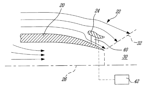
FIG. 2 is a schematic cross-sectional view of an example of a nacelle drag
reduction device; and

FIG. 3 is a schematic cross-sectional view showing the nacelle of FIG. 2
without
the device.


CA 02666190 2009-04-08
WO 2008/058368 3 PCT/CA2007/001812
DETAILED DESCRIPTION

FIG. 1 illustrates a confluent flow turbofan gas turbine engine 10 of a type
preferably provided for use in subsonic flight, generally comprising in serial
flow
communication a fan 12 through which ambient air is propelled, a multistage
compressor 14 for pressurizing the air, a combustor 16 in which the compressed
air is mixed with fuel and ignited for generating an annular stream of hot
combustion gases, and a turbine section 18 for extracting energy from the
combustion gases. The engine 10 is located inside a nacelle 20. In a confluent
flow turbofan engine, such as engine 10, the nacelle 20 at least covers a
significant portion of the aft section of the engine 10. In some designs, it
may
cover the entire aft section.

Referring now to FIG. 2, there is shown a schematic example of the upper half
of
an aft section of the nacelle 20, in a longitudinal cross section, on which is
provided a nacelle drag reduction device 22. The nacelle drag reduction device
22 comprises a hypercritical airfoil 24 which is substantially circular and
axis
symmetrical with reference to the central axis 26 of the aft section of the
nacelle
20. The airfoil 24 is concentric with the aft section of the nacelle 20 and is
located outside or adjacent to the propulsive jet zone 30 defined behind the
engine to avoid excessive flutter. The propulsive jet zone 30 is delimited by
a
boundary, hereafter called the jet boundary 32.

Because of the relatively high momentum of the gases at the outlet of the
engine,
the ambient air surrounding the engine is entrained and thereby accelerated
near
the outer surface of the nacelle 20.

FIG. 3 shows an example of the upper half of a nacelle 20' without the nacelle
drag reduction device. As can be seen, the nacelle rear external flow stream
lines bend inwards. The aft section 20a' of the nacelle 20' is then subjected
to a
low pressure which increases nacelle drag. The jet induced nacelle drag is


CA 02666190 2009-04-08
WO 2008/058368 4 PCT/CA2007/001812
somewhat directly proportional to the jet core flow rate and the mixing
intensity at
the jet boundary 32' behind the engine.

Referring back to FIG. 2, the airfoil 24 deflects ambient air entrained around
the
nacelle 20 to reduce the jet induced nacelle drag. The airfoil 24 is supported
around the nacelle 20 by mean of narrow supports 40 located at various
locations around the circumference of the nacelle 20. The airfoil 24 is
configured
and disposed to improve the nacelle external flow conditions. The exact shape,
angle of attack and configuration of the airfoil 24 will vary in accordance
with the
specific operational parameters of the gas turbine engine.

The optimal position of the airfoil relative to the nacelle, under any
conditions, is
at the location where the flow streamlines have the highest deflection angle
relative to the engine axis and the highest curvature.

In use, operating the engine creates a propulsive jet zone behind it. The
airfoil 24
is provided to deflect ambient air entrained around the nacelle 20. The
airfoil 24
is designed to increase the pressure on the aft section of the nacelle 20, by
reducing or even changing the direction of the stream line curvature at
distances
at least comparable to the airfoil chord. The airfoil lift and drag give a
forward
pointing component while the radial component is cancelled due to symmetry.
The operation of the nacelle drag reduction device 20 can be optimized using
one or more air circulation control devices normally encountered on aircraft
wings
such as trailing edge flaps, leading edge slots, blown flaps, Coanda effect
leading and trailing edge jets, plasma actuators, jet actuators and shape
control
actuators, all of which are generically illustrated in FIG. 2 with the block
diagram
42. These devices 42 may work intermittently, continuously or in a periodic
manner in function of the flight speed and engine thrust settings. If desired,
the
circulation control devices 42 can be used asymmetrically for the purpose of
thrust vectoring.


CA 02666190 2009-04-08
WO 2008/058368 PCT/CA2007/001812
The above description is meant to be exemplary only, and one skilled in the
art
will recognize that other changes may also be made to the embodiments
described without departing from the scope of the invention disclosed as
defined
by the appended claims. For instance, the present invention is not limited to
a
5 nacelle drag reduction device including an airfoil as illustrated in FIG. 2.
Other
shapes can be used as well. Similarly, the turbofan gas turbine engine may be
different from the one shown in FIG. 1. If desired, the airfoil may be
retractable
at high transonic speeds. The airfoil may be provided in different
circumferential
sections separated by spaces. Still other modifications which fall within the
scope of the present invention will be apparent to those skilled in the art,
in light
of a review of this disclosure, and such modifications are intended to fall
within
the appended claims.

Representative Drawing
A single figure which represents the drawing illustrating the invention.
Administrative Status

For a clearer understanding of the status of the application/patent presented on this page, the site Disclaimer , as well as the definitions for Patent , Administrative Status , Maintenance Fee  and Payment History  should be consulted.

Administrative Status

Title Date
Forecasted Issue Date 2013-01-29
(86) PCT Filing Date 2007-10-10
(87) PCT Publication Date 2008-05-22
(85) National Entry 2009-04-08
Examination Requested 2009-04-08
(45) Issued 2013-01-29
Deemed Expired 2020-10-13

Abandonment History

There is no abandonment history.

Payment History

Fee Type Anniversary Year Due Date Amount Paid Paid Date
Request for Examination $200.00 2009-04-08
Application Fee $400.00 2009-04-08
Maintenance Fee - Application - New Act 2 2009-10-13 $100.00 2009-10-08
Maintenance Fee - Application - New Act 3 2010-10-12 $100.00 2010-10-12
Maintenance Fee - Application - New Act 4 2011-10-11 $100.00 2011-09-14
Maintenance Fee - Application - New Act 5 2012-10-10 $200.00 2012-08-17
Final Fee $300.00 2012-11-16
Maintenance Fee - Patent - New Act 6 2013-10-10 $200.00 2013-09-13
Maintenance Fee - Patent - New Act 7 2014-10-10 $200.00 2014-09-17
Maintenance Fee - Patent - New Act 8 2015-10-13 $200.00 2015-09-24
Maintenance Fee - Patent - New Act 9 2016-10-11 $200.00 2016-09-21
Maintenance Fee - Patent - New Act 10 2017-10-10 $250.00 2017-09-20
Maintenance Fee - Patent - New Act 11 2018-10-10 $250.00 2018-09-21
Maintenance Fee - Patent - New Act 12 2019-10-10 $250.00 2019-09-20
Owners on Record

Note: Records showing the ownership history in alphabetical order.

Current Owners on Record
PRATT & WHITNEY CANADA CORP.
Past Owners on Record
ALECU, DANIEL T.
Past Owners that do not appear in the "Owners on Record" listing will appear in other documentation within the application.
Documents

To view selected files, please enter reCAPTCHA code :


To view images, click a link in the Document Description column. To download the documents, select one or more checkboxes in the first column and then click the "Download Selected in PDF format (Zip Archive)" or the "Download Selected as Single PDF" button.

List of published and non-published patent-specific documents on the CPD .

If you have any difficulty accessing content, you can call the Client Service Centre at 1-866-997-1936 or send them an e-mail at CIPO Client Service Centre.


Document
Description 
Date
(yyyy-mm-dd) 
Number of pages   Size of Image (KB) 
Abstract 2009-04-08 1 60
Claims 2009-04-08 2 48
Drawings 2009-04-08 2 31
Description 2009-04-08 5 194
Representative Drawing 2009-06-19 1 11
Cover Page 2009-07-31 2 45
Drawings 2011-11-14 2 30
Claims 2011-11-14 2 48
Representative Drawing 2012-05-14 1 8
Cover Page 2013-01-14 1 40
PCT 2009-04-08 3 80
Assignment 2009-04-08 6 216
Prosecution-Amendment 2009-12-15 1 26
Correspondence 2010-01-20 1 11
Correspondence 2010-01-26 3 100
Prosecution-Amendment 2011-08-26 2 48
Prosecution-Amendment 2011-11-14 5 128
Correspondence 2012-11-16 2 67