Note: Descriptions are shown in the official language in which they were submitted.
CA 02666296 2009-04-08
WO 2008/048448 PCT/US2007/021645
-1-
HEATING AN ORGANIC-RICH ROCK FORMATION IN SITU
TO PRODUCE PRODUCTS WITH IMPROVED
PROPERTIES
CROSS-REFERENCE TO RELATED APPLICATIONS
[00011 This application claims the benefit of U.S. Provisional application
60/XXX,XXX, titled "Products with Improved Aromatic Hydrocarbon Properties
Produced by In Situ Heating of an Organic-Rich Rock Formation", docket No.
2007EM267, which was filed on October 4, 2007, U.S. Provisional application
60/XXX,XXX, titled "Heating an Organic-Rich Rock Formation In Situ to Produce
Products with Improved Aromatic Hydrocarbon Properties", docket No. 2007EM266,
which was filed on October 4, 2007, U.S. Provisional application 60/XXX,XXX,
titled "Products with Improved Branched Hydrocarbon Properties Produced by In
Situ
Heating of an Organic-Rich Rock Formation", docket No. 2007EM269, which was
filed on October 4, 2007, U.S. Provisional application 60/XXX,XXX, titled
"Heating
an Organic-Rich Rock Formation In Situ to Produce Products with Improved
Branched Hydrocarbon Properties", docket No. 2007EM268, which was filed on
October 4, 2007, U.S. Provisional application 60/XXX,XXX, titled "Products
with
Improved Cyclic Hydrocarbon Properties Produced by In Situ Heating of an
Organic-
Rich Rock Formation", docket No. 2007EM271, which was filed on October 4,
2007,
U.S. Provisional application 60/XXX,XXX, titled "Heating an Organic-Rich Rock
Formation In Situ to Produce Products with Improved Cyclic Hydrocarbon
Properties", docket No. 2007EM270, which was filed on October 4, 2007, U.S.
Provisional application 60/XXX,XXX, titled "Products with Identifying Compound
Marker Properties Produced by In Situ Heating of an Organic-Rich Rock
Formation",
docket No. 2007EM272, which was filed on October 4, 2007, U.S. Provisional
application 60/851,432 which was filed on October 13, 2006, U.S. Provisional
application 60/851,534 which was filed on October 13, 2006, U.S. Provisional
application 601851,535 which was filed on October 13, 2006, U.S. Provisional
application 60/851,819 which was filed on October 13, 2006, U.S. Provisional
application 60/851,786 which was filed on October 13, 2006, and U.S. -
Provisional
CA 02666296 2009-04-08
WO 2008/048448 PCT/US2007/021645
-2-
application 60/851,820 which was filed on October 13, 2006. The above-
referenced
provisional applications are incorporated herein in their entirety by
reference.
BACKGROUND OF THE INVENTION
Field of the Invention
[0002] The present invention relates to the field of hydrocarbon recovery from
subsurface formations. More specifically, the present invention relates to in
situ
recovery of hydrocarbon fluids from organic-rich rock formations, including,
for
example, oil shale formations, coal formations and tar sands formations.
Background of the Invention
[0003] Certain geological formations are known to contain an organic matter
known as "kerogen." Kerogen is a solid, carbonaceous material. When kerogen is
imbedded in rock formations, the mixture is referred to as oil shale. This is
true
whether or not the mineral is, in fact, technically shale, that is, a rock
formed from
compacted clay.
[0004] Kerogen is subject to decomposing upon exposure to heat over a period
of
time. Upon heating, kerogen molecularly decomposes to produce oil, gas, and
carbonaceous coke. Small amounts of water may also be generated. The oil, gas
and
water fluids are mobile within the rock matrix, while the carbonaceous coke
remains
essentially immobile.
[0005] Oil shale formations are found in various areas world-wide, including
the
United States. Oil shale formations tend to reside at relatively shallow
depths. In the
United States, oil shale is most notably found in Wyoming, Colorado, and Utah.
These formations are often characterized by limited permeability. Some
consider oil
shale formations to be hydrocarbon deposits which have not yet experienced the
years
of heat and pressure thought to be required to create conventional oil and gas
reserves.
[0006] The decomposition rate of kerogen to produce mobile hydrocarbons is
temperature dependent. Temperatures generally in excess of 270 C(518 F) over
the
course of many months may be required for substantial conversion. At higher
CA 02666296 2009-04-08
WO 2008/048448 PCT/US2007/021645
-3-
temperatures substantial conversion may occur within shorter times. When
kerogen is
heated, chemical reactions break the larger molecules forming the solid
kerogen into
smaller molecules of oil and gas. The thermal conversion process is referred
to as
pyrolysis or retorting.
[0007] Attempts have been made for many years to extract oil from oil shale
formations. Near-surface oil shales have been mined and retorted at the
surface for
over a century. In 1862, James Young began processing Scottish oil shales. The
industry lasted for about 100 years. Commercial oil shale retorting through
surface
mining has been conducted in other countries as well such as Australia,
Brazil, China,
Estonia, France, Russia, South Africa, Spain, and Sweden. However, the
practice has
been mostly discontinued in recent years because it proved to be uneconomical
or
because of environmental constraints on spent shale disposal. (See T.F. Yen,
and
G.V. Chilingarian, "Oil Shale," Amsterdam, Elsevier, p. 292, the entire
disclosure of
which is incorporated herein by reference.) Further, surface retorting
requires mining
of the oil shale, which limits application to very shallow formations.
[0008] In the United States, the existence of oil shale deposits in
northwestern
Colorado has been known since the early 1900's. While research projects have
been
conducted in this area from time to time, no serious commercial development
has
been undertaken. Most research on oil shale production has been carried out in
the
latter half of the 1900's. The majority of this research was on shale oil
geology,
geochemistry, and retorting in surface facilities.
[0009] In 1947, U.S. Pat. No. 2,732,195 issued to Ljungstrom. That patent,
entitled "Method of Treating Oil Shale and Recovery of Oil and Other Mineral
Products Therefrom," proposed the application of heat at high temperatures to
the oil
shale formation in situ to distill and produce hydrocarbons. The `195
Ljungstrom
patent is incorporated herein by reference.
[0010] Ljungstrom coined the phrase "heat supply channels" to describe bore
holes drilled into the formation. The bore holes received an electrical heat
conductor
which transferred heat to the surrounding oil shale. Thus, the heat supply
channels
CA 02666296 2009-04-08
WO 2008/048448 PCT/US2007/021645
-4-
served as heat injection wells. The electrical heating elements in the heat
injection
wells were placed within sand or cement or other heat-conductive material to
permit
the heat injection well to transmit heat into the surrounding oil shale while
preventing
the inflow of fluid. According to Ljungstrom, the "aggregate" was heated to
between
500 and 1,000 C in some applications.
[0011] Along with the heat injection wells, fluid producing wells were also
completed in near proximity to the heat injection wells. As kerogen was
pyrolyzed
upon heat conduction into the rock matrix, the resulting oil and gas would be
recovered through the adjacent production wells.
[0012] Ljungstrom applied his approach of thermal conduction from heated
wellbores through the Swedish Shale Oil Company. A full scale plant was
developed
that operated from 1944 into the 1950's. (See G. Salamonsson, "The Ljungstrom
In
Situ Method for Shale-Oil Recovery," 2"d Oil Shale and Cannel Coal Conference,
v.
2, Glasgow, Scotland, Institute of Petroleum, London, p. 260-280 (1951), the
entire
disclosure of which is incorporated herein by reference.)
[0013] Additional in situ methods have been proposed. These methods generally
involve the injection of heat and/or solvent into a subsurface oil shale. Heat
may be
in the form of heated methane (see U.S. Pat. No. 3,241,611 to J.L. Dougan),
flue gas,
or superheated steam (see U.S. Pat. No. 3,400,762 to D.W. Peacock). Heat may
also
be in the form of electric resistive heating, dielectric heating, radio
frequency (RF)
heating (U.S. Pat. No. 4,140,180, assigned to the ITT Research Institute in
Chicago,
Illinois) or oxidant injection to support in situ combustion. In some
instances,
artificial permeability has been created in the matrix to aid the movement of
pyrolyzed fluids. Permeability generation methods include mining,
rubblization,
hydraulic fracturing (see U.S. Pat. No. 3,468,376 to M.L. Slusser and U.S.
Pat. No.
3,513,914 to J. V. Vogel), explosive fracturing (see U.S. Pat. No. 1,422,204
to W. W.
Hoover, et al.), heat fracturing (see U.S. Pat. No. 3,284,281 to R.W. Thomas),
and
steam fracturing (see U.S. Pat. No. 2,952,450 to H. Purre).
CA 02666296 2009-04-08
WO 2008/048448 PCT/US2007/021645
-5-
[0014] In 1989, U.S. Pat. No. 4,886,118 issued to Shell Oil Company, the
entire
disclosure of which is incorporated herein by reference. That patent, entitled
"Conductively Heating a Subterranean Oil Shale to Create Permeability and
Subsequently Produce Oil," declared that "[c]ontrary to the implications of
... prior
teachings and beliefs ... the presently described conductive heating process
is
economically feasible for use even in a substantially impermeable subterranean
oil
shale." (col. 6, ln. 50-54). Despite this declaration, it is noted that few,
if any,
commercial in situ shale oil operations have occurred other than Ljungstrom's
application. The '118 patent proposed controlling the rate of heat conduction
within
the rock surrounding each heat injection well to provide a uniform heat front.
[0015] Additional history behind oil shale retorting and shale oil recovery
can be
found in co-owned patent publication WO 2005/010320 entitled "Methods of
Treating
a Subterranean Formation to Convert Organic Matter into Producible
Hydrocarbons,"
and in patent publication WO 2005/045192 entitled "Hydrocarbon Recovery from
Impermeable Oil Shales." The Background and technical disclosures of these two
patent publications are incorporated herein by reference.
[0016] A need exists for improved processes for the production of shale oil.
In
addition, a need exists for improved methods of producing shale oil with
improved
properties.
SUMMARY OF THE INVENTION
[0017] In one embodiment, the invention includes a hydrocarbon fluid produced
through in situ pyrolysis of oil shale within an oil shale formation where the
hydrocarbon fluid comprises a condensable hydrocarbon portion and the
condensable
hydrocarbon portion has one or more of a n-C6 to benzene weight ratio less
than 35.0,
a n-C7 to toluene weight ratio less than 7.0, a n-C8 to ethylbenzene weight
ratio less
than 16.0, a n-C8 to ortho-xylene weight ratio less than 7.0, a n-C8 to meta-
xylene
weight ratio less than 1.9, a n-C9 to 1-ethyl-3-methylbenzene weight ratio
less than
8.2, a n-C9 to 1-ethyl-4-methylbenzene weight ratio less than 4.4, a n-C9 to
1,2,4-
trimethylbenzene weight ratio less than 2.7, a n-C10 to 1-ethyl-2,3-
dimethylbenzene
weight ratio less than 13.5, a n-C10 to tetralin weight ratio less than 25.0,
a n-C12 to
CA 02666296 2009-04-08
WO 2008/048448 PCT/US2007/021645
-6-
2-methylnaphthalene weight ratio less than 4.9, and a n-C12 to 1-
methylnaphthalene
weight ratio less than 6.9.
[0018] Another embodiment of the invention includes a hydrocarbon fluid
produced through in situ pyrolysis of oil shale within an oil shale formation
where the
hydrocarbon fluid comprises a condensable hydrocarbon portion and the
condensable
hydrocarbon portion has one or more of a n-C6 to benzene weight ratio less
than 24.0,
a n-C7 to toluene weight ratio less than 6.6, a n-C8 to ethylbenzene weight
ratio less
than 15.0, a n-C8 to ortho-xylene weight ratio less than 6.6, a n-C8 to meta-
xylene
weight ratio less than 1.8, a n-C9 to 1-ethyl-3-methylbenzene weight ratio
less than
7.9, a n-C9 to 1-ethyl-4-methylbenzene weight ratio less than 4.3, a n-C9 to
1,2,4-
trimethylbenzene weight ratio less than 2.6, a n-C 10 to 1-ethyl-2,3-
dimethylbenzene
weight ratio less than 13.1, a n-C10 to tetralin weight ratio less than 23.7,
a n-C12 to
2-methylnaphthalene weight ratio less than 5.0, and a n-C12 to 1-
methylnaphthalene
weight ratio less than 6.8.
[0019] Another embodiment of the invention includes a hydrocarbon fluid
produced through in situ pyrolysis of oil shale within an oil shale formation
where the
hydrocarbon fluid comprises a condensable hydrocarbon portion and the
condensable
hydrocarbon portion has one or more of a n-C6 to benzene weight ratio less
than 13.4,
a n-C7 to toluene weight ratio less than 5.1, a n-C8 to ethylbenzene weight
ratio less
than 12.3, a n-CS to ortho-xylene weight ratio less than 5.3, a n-C8 to meta-
xylene
weight ratio less than 1.5, a n-C9 to 1-ethyl-3-methylbenzene weight ratio
less than
5.9, a n-C9 to 1-ethyl-4-methylbenzene weight ratio less than 3.8, a n-C9 to
1,2,4-
trimethylbenzene weight ratio less than 2.2, a n-C 10 to 1-ethyl-2,3-
dimethylbenzene
weight ratio less than 12.2, a n-C10 to tetralin weight ratio less than 23.4,
a n-C 12 to
2-methylnaphthalene weight ratio less than 4.0, and a n-C12 to 1-
methylnaphthalene
weight ratio less than 6.1.
[0020] In one embodiment, the invention includes an in situ method of
producing
hydrocarbon fluids from an organic-rich rock formation. The method may include
heating in situ a section of an organic-rich rock formation containing
formation
hydrocarbons, where the section of an organic-rich rock formation has a
lithostatic
CA 02666296 2009-04-08
WO 2008/048448 PCT/US2007/021645
-7-
stress greater than 200 psi, pyrolyzing at least a portion of the formation
hydrocarbons
thereby forming a hydrocarbon fluid, and producing the hydrocarbon fluid from
the
organic-rich rock forrimation. The produced hydrocarbon fluid may include a
condensable hydrocarbon portion, where the condensable hydrocarbon portion has
one or more of a n-C6 to benzene weight ratio less than 35.0, a n-C7 to
toluene weight
ratio less than 7.0, a n-C8 =to ethylbenzene weight ratio less than 16.0, a n-
C8 to ortho-
xylene weight ratio less than 7.0, a n-C8 to meta-xylene weight ratio less
than 1.9, a
n-C9 to 1-ethyl-3-methylbenzene weight ratio less than 8.2, a n-C9 to 1-ethyl-
4-
methylbenzene weight ratio less than 4.4, a n-C9 to 1,2,4-trimethylbenzene
weight
ratio less than 2.7, a n-C10 to 1-ethyl-2,3-dimethylbenzene weight ratio less
than
13.5, a n-C10 to tetralin weight ratio less than 25.0, a n-C12 to 2-
methylnaphthalene
weight ratio less than 4.9, and a n-C12 to 1-methylnaphthalene weight ratio
less than
6.9.
[0021] In one embodiment, the invention includes a hydrocarbon fluid produced
through in situ pyrolysis of oil shale within an oil shale formation where the
hydrocarbon fluid comprises a condensable hydrocarbon portion and the
condensable
hydrocarbon portion has one or more of a n-C9 to IP-9 weight ratio greater
than 2.4, a
n-C 10 to IP-10 weight ratio greater than 1.4, a n-C 11 to IP-1 1 weight ratio
greater
than 1.0, a n-C 13 to IP-13 weight ratio greater than 1.1, a n-C 14 to IP-14
weight ratio
greater than 1.1, a n-C 15 to IP-15 weight ratio greater than 1.0, a n-C 16 to
IP-16
weight ratio greater than 0.8, a n-C 18 to IP-18 weight ratio greater than
1.0, and a n-
Cl9 to pristane weight ratio greater than 1.6.
[0022] Another embodiment of the invention includes a hydrocarbon fluid
produced through in situ pyrolysis of oil shale within an oil shale formation
where the
hydrocarbon fluid comprises a condensable hydrocarbon portion and the
condensable
hydrocarbon portion has one or more of a n-C9 to IP-9 weight ratio greater
than 2.5, a
n-C10 to IP-10 weight ratio greater than 1.5, a n-C11 to IP-11 weight ratio
greater
than 1.1, a n-C13 to IP-13 weight ratio greater than 1.2, a n-C14 to IP-14
weight ratio
greater than 1.2, a n-C 15 to IP-15 weight ratio greater than 1.1, a n-C 16 to
IP-16
weight ratio greater than 0.9, a n-C18 to IP-18 weight ratio greater than 1.1,
and a n-
C 19 to pristane weight ratio greater than 1.8.
CA 02666296 2009-04-08
WO 2008/048448 PCT/US2007/021645
-8-
[0023] Another embodiment of the invention includes a hydrocarbon fluid
produced through in situ pyrolysis of oil shale within an oil shale formation
where the
hydrocarbon fluid comprises a condensable hydrocarbon portion and the
condensable
hydrocarbon portion has one or more of a n-C9 to IP-9 weight ratio greater
than 2.6, a
n-C 10 to IP- 10 weight ratio greater than 1.6, a n-C 11 to IP- 11 weight
ratio greater
than 1.2, a n-C13 to IP-13 weight ratio greater than 1.3, a n-C14 to IP-14
weight ratio
greater than 1.4, a n-C 15 to IP-15 weight ratio greater than 1.4, a n-C 16 to
IP-16
weight ratio greater than 1.2, a n-C18 to IP-1 8 weight ratio greater than
1.5, and a n-
C 19 to pristane weight ratio greater than 2.4.
[0024] In one embodiment, the invention includes an in situ method of
producing
hydrocarbon fluids from an organic-rich rock formation. The method may include
heating in situ a section of an organic-rich rock formation containing
formation
hydrocarbons, where the section of an organic-rich rock formation has a
lithostatic
stress greater than 200 psi, pyrolyzing at least a portion of the formation
hydrocarbons
thereby forming a hydrocarbon fluid, and producing the hydrocarbon fluid from
the
organic-rich rock formation. The produced hydrocarbon fluid may include a
condensable hydrocarbon portion, where the condensable hydrocarbon portion has
one or more of a n-C9 to IP-9 weight ratio greater than 2.4, a n-C10 to IP-10
weight
ratio greater than 1.4, a n-C 11 to IP-11 weight ratio greater than 1.0, a n-C
13 to IP- 13
weight ratio greater than 1.1, a n-C14 to IP-14 weight ratio greater than 1.1,
a n-C15
to IP-15 weight ratio greater than 1.0, a n-C16 to IP-16 weight ratio greater
than 0.8, a
n-C18 to IP-18 weight ratio greater than 1.0, and a n-C19 to pristane weight
ratio
greater than 1.6.
[0025] In one embodiment, the invention includes a hydrocarbon fluid produced
through in situ pyrolysis of oil shale within an oil shale formation where the
hydrocarbon fluid comprises a condensable hydrocarbon portion and the
condensable
hydrocarbon portion has one or more of a n-C7 to cis 1,3-dimethyl cyclopentane
weight ratio less than 13.1, a n-C7 to trans 1,3-dimethyl cyclopentane weight
ratio
less than 14.9, a n-C7 to trans 1,2-dimethyl cyclopentane weight ratio less
than 7.0, a
n-C7 to methyl cyclohexane weight ratio less than 5.2, a n-C7 to ethyl
cyclopentane
weight ratio less than 11.3, a n-C8 to 1,1-dimethyl cyclohexane weight ratio
less than
CA 02666296 2009-04-08
WO 2008/048448 PCT/US2007/021645
-9-
16.0, a n-C8 to trans 1,2-dimethyl cyclohexane weight ratio less than 17.5,
and a n-C8
to ethyl cyclohexane weight ratio less than 12.3.
[0026] Another embodiment of the invention includes a hydrocarbon fluid
produced through in situ pyrolysis of oil shale within an oil shale formation
where the
hydrocarbon fluid comprises a condensable hydrocarbon portion and the
condensable
hydrocarbon portion has one or more of a n-C7 to cis 1,3-dimethyl cyclopentane
weight ratio less than 12.7, a n-C7 to trans 1,3-dimethyl cyclopentane weight
ratio
less than 14.7, a n-C7 to trans 1,2-dimethyl cyclopentane weight ratio less
than 6.6, a
n-C7 to methyl cyclohexane weight ratio less than 5.0, a n-C7 to ethyl
cyclopentane
weight ratio less than 10.9, a n-C8 to 1,1-dimethyl cyclohexane weight ratio
less than
15.4, a n-C8 to trans 1,2-dimethyl cyclohexane weight ratio less than 16.5,
and a n-C8
to ethyl cyclohexane weight ratio less than 12Ø
[0027] Another embodiment of the invention includes a hydrocarbon fluid
produced through in situ pyrolysis of oil shale within an oil shale formation
where the
hydrocarbon fluid comprises a condensable hydrocarbon portion and the
condensable
hydrocarbon portion has one or more of a n-C7 to cis 1,3-dimethyl cyclopentane
weight ratio less than 10.3, a n-C7 to trans 1,3-dimethyl cyclopentane weight
ratio
less than 11.6, a n-C7 to trans 1,2-dimethyl cyclopentane weight ratio less
than 5.9, a
n-C7 to methyl cyclohexane weight ratio less than 4.1, a n-C7 to ethyl
cyclopentane
weight ratio less than 9.5, a n-C8 to 1,1-dimethyl cyclohexane weight ratio
less than
13.9, a n-C8 to trans 1,2-dimethyl cyclohexane weight ratio less than 12.3,
and a n-C8
to ethyl cyclohexane weight ratio less than 10.3.
[0028] In one embodiment, the invention includes an in situ method of
producing
hydrocarbon fluids from an organic-rich rock formation. The method may include
heating in situ a section of an organic-rich rock formation containing
formation
hydrocarbons, where the section of an organic-rich rock formation has a
lithostatic
stress greater than 200 psi, pyrolyzing at least a portion of the formation
hydrocarbons
thereby forming a hydrocarbon fluid, and producing the hydrocarbon fluid from
the
organic-rich rock formation. The produced hydrocarbon fluid may include a
condensable hydrocarbon portion, where the condensable hydrocarbon portion has
CA 02666296 2009-04-08
WO 2008/048448 PCT/US2007/021645
-10-
one or more of a n-C7 to cis 1,3-dimethyl cyclopentane weight ratio less than
13.1, a
n-C7 to trans 1,3-dimethyl cyclopentane weight ratio less than 14.9, a n-C7 to
trans
1,2-dimethyl cyclopentane weight ratio less than 7.0, a n-C7 to methyl
cyclohexane
weight ratio less than 5.2, a n-C7 to ethyl cyclopentane weight ratio less
than 11.3, a
n-C8 to 1,1-dimethyl cyclohexane weight ratio less than 16.0, a n-C8 to trans
1,2-
dimethyl cyclohexane weight ratio less than 17.5, and a n-C8 to ethyl
cyclohexane
weight ratio less than 12.3.
[0029] In one embodiment, the invention includes a hydrocarbon fluid produced
through in situ pyrolysis of oil shale within an oil shale formation. The
hydrocarbon
fluid including a condensable hydrocarbon portion. The condensable hydrocarbon
portion having one or more of a total C9 to total C20 weight ratio between 2.5
and
6.0, a total C 10 to total C20 weight ratio between 2.8 and 7.3, a total C 11
to total C20
weight ratio between 2.6 and 6.5, a total C12 to total C20 weight ratio
between 2.6
and 6.4 and a total C13 to total C20 weight ratio between 3.2 and 8Ø
[0030] Another embodiment of the invention includes a hydrocarbon fluid
produced through in situ pyrolysis of oil shale within an oil shale formation.
The
hydrocarbon fluid including a condensable hydrocarbon portion. The condensable
hydrocarbon portion having one or more of a total C10 to total C25 weight
ratio
between 7.1 and 24.5, a total C 11 to total C25 weight ratio between 6.5 and
22.0, a
total C 12 to total C25 weight ratio between 6.5 and 22.0, and a total C 13 to
total C25
weight ratio between 8.0 and 27Ø
[0031] Another embodiment of the invention includes a hydrocarbon fluid
produced through in situ pyrolysis of oil shale within an oil shale formation.
The
hydrocarbon fluid including a condensable hydrocarbon portion. The condensable
hydrocarbon portion having one or more of a total C10 to total C29 weight
ratio
between 15.0 and 60.0, a total C 11 to total C29 weight ratio between 13.0 and
54.0, a
total C12 to total C29 weight ratio between 12.5 and 53.0, and a total C13 to
total C29
weight ratio between 16.0 and 65Ø
CA 02666296 2009-04-08
WO 2008/048448 PCT/US2007/021645
-11-
[0032] In one embodiment, the invention includes an in situ method of
producing
hydrocarbon fluid from an organic-rich rock formation. The method includes
heating
in situ a section of an organic-rich rock formation having a lithostatic
stress greater
than 200 psi. The method further includes producing a hydrocarbon fluid from
the
organic-rich rock formation. The produced hydrocarbon fluid including a
condensable hydrocarbon portion. The condensable hydrocarbon portion having
one
or more of a total C7 to total C20 weight ratio greater than 0.8, a total C8
to total C20
weight ratio greater than 1.7, a total C9 to total C20 weight ratio greater
than 2.5, a
total C10 to total C20 weight ratio greater than 2.8, a total C11 to total C20
weight
ratio greater than 2.3, a total C12 to total C20 weight ratio greater than
2.3, a total
C13 to total C20 weight ratio greater than 2.9, a total C14 to total C20
weight ratio
greater than 2.2, a total C 15 to total C20 weight ratio greater than 2.2, and
a total C 16
to total C20 weight ratio greater than 1.6.
[0033] In one embodiment, the invention includes an in situ method of
producing
hydrocarbon fluid from an organic-rich rock formation. The method includes
heating
in situ a section of an organic-rich rock formation having a lithostatic
stress greater
than 200 psi. The method further includes producing a hydrocarbon fluid from
the
organic-rich rock formation. The produced hydrocarbon fluid including a
condensable hydrocarbon portion. The condensable hydrocarbon portion having
one
or more of a total C7 to total C25 weight ratio greater than 2.0, a total C8
=to total C25
weight ratio greater than 4.5, a total C9 to total C25 weight ratio greater
than 6.5, a
total C 10 to total C25 weight ratio greater than 7.5, a total C 11 to total
C25 weight
ratio greater than 6.5, a total C12 to total C25 weight ratio greater than
6.5, a total
C13 to total C25 weight ratio greater than 8.0, a total C14 to total C25
weight ratio
greater than 6.0, a total C 15 to total C25 weight ratio greater than 6.0, a
total C 16 to
total C25 weight ratio greater than 4.5, a total C17 to total C25 weight ratio
greater
than 4.8, and a total C18 to total C25 weight ratio greater than 4.5.
(0034] In one embodiment, the invention includes an in situ method of
producing
hydrocarbon fluid from an organic-rich rock formation. The method includes
heating
in situ a section of an organic-rich rock formation having a lithostatic
stress greater
than 200 psi. The method further includes producing a hydrocarbon fluid from
the
CA 02666296 2009-04-08
WO 2008/048448 PCT/US2007/021645
-12-
organic-rich rock formation. The produced hydrocarbon fluid including a
condensable hydrocarbon portion. The condensable hydrocarbon portion having
one
or more of a total C7 to total C29 weight ratio greater than 3.5, a total C8
to total C29
weight ratio greater than 9.0, a total C9 to total C29 weight ratio greater
than 12.0, a
total C10 to total C29 weight ratio greater than 15.0, a total C11 to total
C29 weight
ratio greater than 13.0, a total C12 to total C29 weight ratio greater than
12.5, a total
C13 to total C29 weight ratio greater than 16.0, a total C14 to tota1-C29
weight ratio
greater than 12.0, a total C15 to total C29 weight ratio greater than 12.0, a
total C16 to
total C29 weight ratio greater than 9.0, a total C17 to total C29 weight ratio
greater
than 10.0, a total C 18 to total C29 weight ratio greater than 8.8, a total C
19 to total
C29 weight ratio greater than 7.0, a total C20 to total C29 weight ratio
greater than
6.0, a total C21 to total C29 weight ratio greater than 5.5, and a total C22
to total C29
weight ratio greater than 4.2.
[0035] In one embodiment, the invention includes a hydrocarbon fluid produced
through in situ pyrolysis of oil shale within an oil shale formation. The
hydrocarbon
fluid including a condensable hydrocarbon portion. The condensable hydrocarbon
portion having one or more of a normal-C7 to normal-C20 weight ratio greater
than
0.9, a normal-C8 to normal-C20 weight ratio greater than 2.0, a normal-C9 to
normal-
C20 weight ratio greater than 1.9, a normal-C 10 to normal-C20 weight ratio
greater
than 2.2; a normal-C 11 to normal-C20 weight ratio greater than 1.9, a normal-
C 12 to
normal-C20 weight ratio greater than 1.9, a normal-C 13 to normal-C20 weight
ratio
greater than 2.3, a normal-C14 to normal-C20 weight ratio greater than 1.8, a
norrnal-
C15 to normal-C20 weight ratio greater than 1.8, and normal-C16 to normal-C20
weight ratio greater than 1.3.
[0036] Another embodiment of the invention includes a hydrocarbon fluid
produced through in situ pyrolysis of oil shale within an oil shale formation.
The
hydrocarbon fluid including a condensable hydrocarbon portion. The condensable
hydrocarbon portion having one or more of a normal-C7 to normal-C25 weight
ratio
greater than 1.9, a normal-C8 to normal-C25 weight ratio greater than 3.9, a
normal-
C9 to normal-C25 weight ratio greater than 3.7, a normal-C10 to normal-C25
weight
ratio greater than 4.4, a normal-C11 to normal-C25 weight ratio greater than
3.8, a
CA 02666296 2009-04-08
WO 2008/048448 PCT/US2007/021645
-13-
normal-C12 to normal-C25 weight ratio greater than 3.7, a normal-C13 to normal-
C25 weight ratio greater than 4.7, a normal-C14 to normal-C25 weight ratio
greater
than 3.7, a normal-C15 to normal-C25 weight ratio greater than 3.7, a normal-
C16 to
normal-C25 weight ratio greater than 2.5, a normal-C17 to normal-C25 weight
ratio
greater than 3.0, and a normal-C18 to normal-C25 weight ratio greater than
3.4.
[0037] Another embodiment of the invention includes a hydrocarbon fluid
produced through in situ pyrolysis of oil shale within an oil shale formation.
The
hydrocarbon fluid including a condensable hydrocarbon portion. The condensable
hydrocarbon portion having one or more of a normal-C7 to normal-C29 weight
ratio
greater than 18.0, a normal-C8 to normal-C29 weight ratio greater than 16.0, a
normal-C9 to normal-C29 weight ratio greater than 14.0, a normal-C l0 to
normal-
C29 weight ratio greater than 14.0, a normal-Cl 1 to normal-C29 weight ratio
greater
than 13.0, a normal-C 12 to normal-C29 weight ratio greater than 11.0, a
normal-C 13
to normal-C29 weight ratio greater than 10.0, a normal-C 14 to normal-C29
weight
ratio greater than 9.0, a normal-C15 to normal-C29 weight ratio greater than
8.0, a
normal-C16 to normal-C29 weight ratio greater than 8.0, a normal-C17 to normal-
C29 weight ratio greater than 6.0, a normal-C18 to normal-C29 weight ratio
greater
than 6.0, a normal-C 19 to normal-C29 weight ratio greater than 5.0, a normal-
C20 to
normal-C29 weight ratio greater than 4.0, a normal-C21 to normal-C29 weight
ratio
greater than 3.6, and a normal-C22 to normal-C29 weight ratio greater than
2.8.
[0038] In one embodiment, the invention includes an in situ method of
producing
hydrocarbon fluid from an organic-rich rock formation. The method includes
heating
in situ a section of an organic-rich rock formation having a lithostatic
stress greater
than 200 psi. The method further includes producing a hydrocarbon fluid from
the
organic-rich rock formation. The produced hydrocarbon fluid including a
condensable hydrocarbon portion. The condensable hydrocarbon portion having
one
or more of a normal-C 10 to normal-C20 weight ratio greater than 2.2, a normal-
C 11
to normal-C20 weight ratio greater than 1.9, a normal-C 12 to normal-C20
weight ratio
greater than 1.9, a normal-C13 to normal-C20 weight ratio greater than 2.3, a
normal-
C14 to normal-C20 weight ratio greater than 1.8, a normal-C15 to normal-C20
weight
ratio greater than 1.8, and normal-C16 to normal-C20 weight ratio greater than
1.3.
CA 02666296 2009-04-08
WO 2008/048448 PCT/US2007/021645
-14-
[0039] In one embodiment, the invention includes an in situ method of
producing
hydrocarbon fluid from an organic-rich rock formation. The method includes
heating
in situ a section of an organic-rich rock formation having a lithostatic
stress greater
than 200 psi. The method further includes producing a hydrocarbon fluid from
the
organic-rich rock formation. The produced hydrocarbon fluid including a
condensable hydrocarbon portion. The condensable hydrocarbon portion having
one
or more of a normal-C10 to normal-C25 weight ratio greater than 4.4, a normal-
CI1
to normal-C25 weight ratio greater than 3.8, a normal-C 12 to normal-C25
weight ratio
greater than 3.7, a normal-C13 to normal-C25 weight ratio greater than 4.7, a
normal-
C 14 to normal-C25 weight ratio greater than 3.7, a normal-C 15 to normal-C25
weight
ratio greater than 3.7, a normal-C16 to normal-C25 weight ratio greater than
2.5, a
normal-C17 to normal-C25 weight ratio greater than 3.0, and a normal-C18 to
normal-C25 weight ratio greater than 3.4.
[0040] In one embodiment, the invention includes an in situ method of
producing
hydrocarbon fluid from an organic-rich rock formation. The method includes
heating
in situ a section of an organic-rich rock formation having a lithostatic
stress greater
than 200 psi. The method further includes producing a hydrocarbon fluid from
the
organic-rich rock formation. The produced hydrocarbon fluid including a
condensable hydrocarbon portion. The condensable hydrocarbon portion having
one
or more of a normal-C7 to normal-C29 weight ratio greater than 18.0, a normal-
C8 to
normal-C29 weight ratio greater than 16.0, a normal-C9 to normal-C29 weight
ratio
greater than 14.0, a normal-ClO to normal-C29 weight ratio greater than 14.0,
a
normal-C 11 to normal-C29 weight ratio greater than 13.0, a normal-C 12 to
normal-
C29 weight ratio greater than 11.0, a normal-C 13 to normal-C29 weight ratio
greater
than 10.0, a normal-C 14 to normal-C29 weight ratio greater than 9.0, a normal-
C 15 to
normal-C29 weight ratio greater than 8.0, a normal-C16 to normal-C29 weight
ratio
greater than 8.0, a normal-C17 to normal-C29 weight ratio greater than 6.0, a
normal-
C 18 to normal-C29 weight ratio greater than 6.0, a normal-C 19 to normal-C29
weight
ratio greater than 5.0, a normal-C20 to normal-C29 weight ratio greater than
4.0, a
normal-C21 to normal-C29 weight ratio greater than 3.6, and a normal-C22 to
normal-C29 weight ratio greater than 2.8.
CA 02666296 2009-04-08
WO 2008/048448 PCT/US2007/021645
-15-
[0041] In one embodiment, the invention includes a hydrocarbon fluid produced
through in situ pyrolysis of oil shale within an oil shale formation. The
hydrocarbon
fluid including a condensable hydrocarbon portion. The condensable hydrocarbon
portion having one or more of a normal-C 10 to total C10 weight ratio less
than 0.31, a
normal-C 11 to total C 11 weight ratio less than 0.32, a normal-C12 to total
C12 weight
ratio less than 0.29, a normal-C13 to total C13 weight ratio less than 0.28, a
normal-
C14 to total C14 weight ratio less than 0.31, a normal-C15 to total C15 weight
ratio
less than 0.27, a normal-C 16 to total C 16 weight ratio less than 0.31, a
normal-C 17 to
total C 17 weight ratio less than 0.31, a normal-C 18 to total C 18 weight
ratio less than
0.37, normal-C19 to total C19 weight ratio less than 0.37, a normal-C20 to
total C20
weight ratio less than 0.37, a normai-C21 to total C21 weight ratio less than
0.37, a
normal-C22 to total C22 weight ratio less than 0.38, normal-C23 to total C23
weight
ratio less than 0.43, a normal-C24 to total C24 weight ratio less than 0.48,
and a
normal-C25 to total C25 weight ratio less than 0.53.
[0042] In one embodiment, the invention includes an in situ method of
producing
hydrocarbon fluid from an organic-rich rock formation. The method includes
heating
in situ a section of an organic-rich rock formation having a lithostatic
stress greater
than 200 psi. The method further includes producing a hydrocarbon fluid from
the
organic-rich rock formation. The produced hydrocarbon fluid including a
condensable hydrocarbon portion. The condensable hydrocarbon portion having
one
or more of a normal-C 10 to total C 10 weight ratio less than 0.31, a normal-C
11 to
total C 11 weight ratio less than 0.32, a normal-C 12 to total C 12 weight
ratio less than
0.29, a nonnal-C 13 to total C 13 weight ratio less than 0.28, a nonnal-C 14
to total C 14
weight ratio less than 0.31, a normal-C15 to total C15 weight ratio less than
0.27, a
normal-C16 to total C16 weight ratio less than 0.31, a normal-C 17 to total
C17 weight
ratio less than 0.31, a normal-C18 to total C18 weight ratio less than 0.37,
normal-
C 19 to total C19 weight ratio less than 0.37, a normal-C20 to total C20
weight ratio
less than 0.37, a normal-C21 to total C21 weight ratio less than 0.37, a
normal-C22 to
total C22 weight ratio less than 0.38, normal-C23 to total C23 weight ratio
less than
0.43, a normal-C24 to total C24 weight ratio less than 0.48, and a normal-C25
to total
C25 weight ratio less than 0.53.
CA 02666296 2009-04-08
WO 2008/048448 PCT/US2007/021645
-16-
BRIEF DESCRIPTION OF THE DRAWINGS
[0043] So that the manner in which the features of the present invention can
be
better understood, certain drawings, graphs and flow charts are appended
hereto. It is
to be noted, however, that the drawings illustrate only selected embodiments
of the
inventions and are therefore not to be considered limiting of scope, for the
inventions
may admit to other equally effective embodiments and applications.
[0044] Figure 1 is a cross-sectional view of an illustrative subsurface area.
The
subsurface area includes an organic-rich rock matrix that defines a subsurface
formation.
[0045] Figure 2 is a flow chart demonstrating a general method of in situ
thermal
recovery of oil and gas from an organic-rich rock formation, in one
embodiment.
[0046] Figure 3 is a cross-sectional view of an illustrative oil shale
formation that
is within or connected to groundwater aquifers and a formation leaching
operation.
[0047] Figure 4 is a plan view of an illustrative heater well pattern, around
a
production well. Two layers of heater wells are shown.
[0048] Figure 5 is a bar chart comparing one ton of Green River oil shale
before
and after a simulated in situ, retorting process.
[0049] Figure 6 is a process flow diagram of exemplary surface processing
facilities for a subsurface formation development.
[0050] Figure 7 is a graph of the weight percent of each carbon number pseudo
component occurring from C6 to C38 for laboratory experiments conducted at
three
different stress levels.
[0051] Figure 8 is a graph of the weight percent ratios of each carbon number
pseudo component occurring from C6 to C38 as compared to the C20 pseudo
component for laboratory experiments conducted at three different stress
levels.
CA 02666296 2009-04-08
WO 2008/048448 PCT/US2007/021645
-17-
[0052] Figure 9 is a graph of the weight percent ratios of each carbon number
pseudo component occurring from C6 to C38 as compared to the C25 pseudo
component for laboratory experiments conducted at three different stress
levels.
[0053] Figure 10 is a graph of the weight percent ratios of each carbon number
pseudo component occurring from C6 to C38 as compared to the C29 pseudo
component for laboratory experiments conducted at three different stress
levels.
[0054] Figure 11 is a graph of the weight percent of normal alkane hydrocarbon
compounds occurring from normal-C6 to normal-C38 for laboratory experiments
conducted at three different stress levels.
[0055] Figure 12 is a graph of the weight percent of normal alkane hydrocarbon
compounds occurring from normal-C6 to normal-C38 as compared to the normal-C20
hydrocarbon compound for laboratory experiments conducted at three different
stress
levels.
[0056] Figure 13 is a graph of the weight percent of normal alkane hydrocarbon
compounds occurring from normal-C6 to normal-C38 as compared to the normal-C25
hydrocarbon compound for laboratory experiments conducted at three different
stress
levels.
[0057] Figure 14 is a graph of the weight percent of normal alkane hydrocarbon
compounds occurring from normal-C6 to normal-C38 as compared to the normal-C29
hydrocarbon compound for laboratory experiments conducted at three different
stress
levels.
[0058] Figure 15 is a graph of the weight ratio of normal alkane hydrocarbon
compounds to pseudo components for each carbon number from C6 to C38 for
laboratory experiments conducted at three different stress levels.
[0059] Figure 16 is a bar graph showing the concentration, in molar
percentage, of
the hydrocarbon species present in the gas samples taken from duplicate
laboratory
experiments conducted at three different stress levels.
CA 02666296 2009-04-08
WO 2008/048448 PCT/US2007/021645
-18-
[0060] Figure 17 is an exemplary view of the gold tube apparatus used in the
unstressed Parr heating test described in Example 1.
[0061] Figure 18 is a cross-sectional view of the Parr vessel used in Examples
1-
5.
[0062] Figure 19 is gas chromatogram of gas sampled from Example 1.
[0063] Figure 20 is a whole oil gas chromatogram of liquid sampled from
Example 1.
[0064] Figure 21 is an exemplary view of a Berea cylinder, Berea plugs, and an
oil shale core specimen as used in Examples 2-5.
[0065] Figure 22 is an exemplary view of the mini load frame and sample
assembly used in Examples 2-5.
[0066] Figure 23 is gas chromatogram of gas sampled from Example 2.
[0067] Figure 24 is gas chromatogram of gas sampled from Example 3.
[0068] Figure 25 is a whole oil gas chromatogram of liquid sampled from
Example 3.
[0069] Figure 26 is gas chromatogram of gas sampled from Example 4.
[0070] Figure 27 is a whole oil gas chromatogram of liquid sampled from
Example 4.
[0071] Figure 28 is gas chromatogram of gas sampled from Example 5.
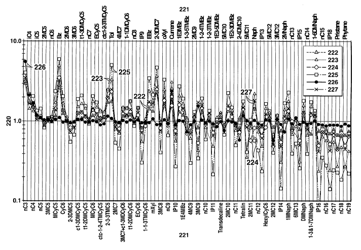
[0072] Figure 29 is a graph of the weight ratio of each identified compound
occurring from n-C3 to n-C19 for each of the six 393 C experiments (Examples
13-
19) compared to the weight ratio of each identified compound occurring from n-
C3 to
n-C 19 for Example 13 conducted at 393 C, 500 psig initial argon pressure and
0 psi
stress.
CA 02666296 2009-04-08
WO 2008/048448 PCT/US2007/021645
-19-
[0073] Figure 30 is a bar graph of the weight ratio of several normal
hydrocarbon
compounds to like carbon number aromatic hydrocarbon compounds for each of the
seven 393 C experiments (Examples 13-19) discussed in the Experimental section
herein.
[0074] Figure 31 is a bar graph of the weight ratio of several normal
hydrocarbon
compounds to like carbon number aromatic hydrocarbon compounds for each of the
seven 375 C experiments (Examples 6-12) discussed in the Experimental section
herein.
[0075] Figure 32 is a bar graph of the weight ratio of several normal
hydrocarbon
compounds to like carbon number aromatic hydrocarbon compounds for each of the
seven 375 C and seven 393 C experiments (Examples 6-19) discussed in the
Experimental section herein.
[0076] Figure 33 is a bar graph of the weight ratio of several normal
hydrocarbon
compounds to like carbon number aromatic hydrocarbon compounds for each of the
seven 375 C and seven 393 C experiments (Examples 6-19) discussed in the
Experimental section herein.
[0077] Figure 34 is a bar graph of the weight ratio of several normal
hydrocarbon
compounds to like carbon number cyclic hydrocarbon compounds for each of the
seven 393 C experiments (Examples 13-19) discussed in the Experimental section
herein.
[0078] Figure 35 is a bar graph of the weight ratio of several normal
hydrocarbon
compounds to like carbon number cyclic hydrocarbon compounds for each of the
seven 375 C and seven 393 C experiments (Examples 6-19) discussed in the
Experimental section herein.
[0079] Figure 36 is a bar graph of the weight ratio of several normal
hydrocarbon
compounds to like carbon number isoprenoid hydrocarbon compounds for each of
the
seven 393 C experiments (Examples 13-19) discussed in the Experimental section
herein.
CA 02666296 2009-04-08
WO 2008/048448 PCT/US2007/021645
-20-
[0080] Figure 37 is a bar graph of the weight ratio of several normal
hydrocarbon=
compounds to like carbon number isoprenoid hydrocarbon compounds for each of
the
seven 375 C and seven 393 C experiments (6-19) discussed in the Experimental
section herein.
[0081] Figure 38 is a bar graph of the weight ratio of the certain hydrocarbon
compounds to similar carbon number isoprenoid hydrocarbon compounds for each
of
thc sevcn 375 C and seven 393 C experiments (Examples 6-19) discussed in the
Experimental section herein.
[0082] Figure 39 is a C4-C19 GC chromatogram for hydrocarbon liquid sampled
in Example 6.
[0083] Figure 40 is a C4-C19 GC chromatogram for hydrocarbon liquid sampled
in Example 7.
[0084] Figure 41 is a C4-C 19 GC ch.romatogram for hydrocarbon liquid sampled
in Example 8.
[0085] Figure 42 is a C4-C19 GC chromatogram for hydrocarbon liquid sampled
in Example 9.
[0086] Figure 43 is a C4-C 19 GC chromatogram for hydrocarbon liquid sampled
in Example 10.
[0087] Figure 44 is a C4-C 19 GC chromatogram for hydrocarbon liquid sampled
in Example 11.
[0088] Figure 45 is a C4-C19 GC chromatogram for hydrocarbon liquid sampled
in Example 12.
[0089] Figure 46 is a C4-C19 GC chromatogram for hydrocarbon liquid sampled
in Example 13.
[0090] Figure 47 is a C4-C19 GC chromatogram for hydrocarbon liquid sampled
in Example 14.
CA 02666296 2009-04-08
WO 2008/048448 PCT/US2007/021645
-21-
[0091] Figure 48 is a C4-C19 GC chromatogram for hydrocarbon liquid sampled
in Example 15.
10092] Figure 49 is a C4-C19 GC chromatogram for hydrocarbon liquid sampled
in Example 16.
[0093] Figure 50 is a C4-C19 GC chromatogram for hydrocarbon liquid sampled
in Example 17.
[0094] Figure 51 is a C4-C19 GC chromatogram for hydrocarbon liquid sampled
in Example 18.
10095] Figure 52 is a C4-C19 GC chromatogram for hydrocarbon liquid sampled
in Example 19.
[0096] Figure 53 is a plot of the weight ratio of (trisnorhopane maturable) to
(trisnorhopane maturable + trisnorhopane stable) for Examples 6-20.
[0097] Figure 54 is a plot of the weight ratio of [C-29 17a(H), 21[3(H)
hopanel to
[C-29 17a(H), 21 [3(H) hopane + C-2917(3(H), 21(3(H) hopane] for Examples 6-
20.
[0098] Figure 55 is a plot of the weight ratio of [C-30 17a(H), 21[3(H)
hopane] to
[C-30 17a(H), 21(3(H) hopane + C-30 17R(H), 21(3(H) hopane] for Examples 6-20.
[0099] Figure 56 is a plot of the weight ratio of [C-31 17a(H), 21 [3(H), 22S
homohopane] to [C-31 17a(H), 21(3(H), 22S homohopane + C-31 17a(H), 21(3(H),
22R homahopane] for Examples 6-20.
[0100] Figure 57 is a plot of the weight ratio of [C-29 5 a, 14 a, 17 a(H) 20R
steranes] to [C-29 5 a, 14 a, 17 a(H) 20R steranes + C-29 5 a, 14 a, 17 a (H)
20S
steranes] for examples 6-20.
[0101] Figure 58 is a plot of the weight ratio of [C-29.5 a, 14 (3, 17 0 (H)
20S +
C-29 5 a., 14 (3, 17 (3 (H) 20R steranes] to [C-29 5 a, 14 P, 17 (3 (H) 20S +
C-29 5 a,
CA 02666296 2009-04-08
WO 2008/048448 PCT/US2007/021645
-22-
14 P, 17 (3 (H) 20R steranes + C-29 5 a, 14 a, 17 a(H) 20S + C-29 5 a, 14 a,
17 a
(H) 20R steranes] for Examples 6-20.
[0102] Figure 59 is a plot of the weight ratio of 3-methyl phenanthrene (3-MP)
+
2-methyl'-phenanthrene (2-MP) to 1-methyl phenanthrene (1-MP) + 9-methyl
phenanthrene (9-MP) for Examples 6-20.
[0103] Figure 60 is a graph of the weight ratio of each identified compound
occurring from i-C4 to n-C35 for each of the six 393 C experiments (Examples
13-
19) compared to the weight ratio of each identified compound occurring from i-
C4 to
n-C35 for Example 13 conducted at 393 C, 500 psig initial argon pressure and 0
psi
stress.
[0104] Figure 61 is a graph of the weight ratio of each identified compound
occurring from i-C4 to n-C35 for each of the six 375 C experiments (Examples 7-
12)
compared to the weight ratio of each identified compound occurring from i-C4
to n-
C35 for Example 6 conducted at 375 C, 500 psig initial argon pressure and 0
psi
stress.
[0105] Figure 62 is a photograph of an unheated oil shale core plug used in
experiments described herein.
[0106] Figure 63 is a photograph of a thin section detail of the unheated oil
shale
core plug depicted in Figure 62.
[0107] Figure 64 is a photograph of an oil shale core plug that has been
heated
under no stress as used in experiments described herein.
[0108] Figure 65 is a photograph of a thin section detail of the unstressed
and
heated oil shale core plug depicted in Figure 64.
[0109] Figure 66 is a photograph of an oil shale core plug that has been
heated
under stress as used in experiments described herein.
[0110] Figure 67 is a photograph of a thin section detail of the stressed and
heated
oil shale core plug depicted in Figure 66.
CA 02666296 2009-04-08
WO 2008/048448 PCT/US2007/021645
-23-
DETAILED DESCRIPTION OF CERTAIN EMBODIMENTS
Definitions
[0111] As used herein, the term "hydrocarbon(s)" refers to organic material
with
molecular structures containing carbon bonded to hydrogen. Hydrocarbons may
also
include other elements, such as, but not limited to, halogens, metallic
elements,
nitrogen, oxygen, and/or sulfur.
[0112] As used herein, the term "hydrocarbon . ui s" refers to a hydrocarbon
or
mixtures of hydrocarbons that are gases or liquids. For example, hydrocarbon
fluids
may include a hydrocarbon or mixtures of hydrocarbons that are gases or
liquids at
formation conditions, at processing conditions or at .ambient conditions (15
C and 1
atm pressure). Hydrocarbon fluids may include, for example, oil, natural gas,
coal
bed methane, shale oil, pyrolysis oil, pyrolysis gas, a pyrolysis product of
coal, and
other hydrocarbons that are in a gaseous or liquid state.
[0113] As used herein, the terms "produced fluids" and "production fluids"
refer
to liquids and/or gases removed from a subsurface formation, including, for
example,
an organic-rich rock formation. Produced fluids may include both hydrocarbon
fluids
and non-hydrocarbon fluids. Production fluids may include, but are not limited
to,
pyrolyzed shale oil, synthesis gas, a pyrolysis product of coal, carbon
dioxide,
hydrogen sulfide and water (including steam). Produced fluids may include both
hydrocarbon fluids and non-hydrocarbon fluids.
[0114] As used herein, the term "condensable hydrocarbons" means those
hydrocarbons that condense at 25 C and one atmosphere absolute pressure.
Condensable hydrocarbons may include a mixture of hydrocarbons having carbon
numbers greater than 4.
[0115] As used herein, the term "non-condensable hydrocarbons" means those
hydrocarbons that do not condense at 25 C and one atmosphere absolute
pressure.
Non-condensable hydrocarbons may include hydrocarbons having carbon numbers
less than 5.
CA 02666296 2009-04-08
WO 2008/048448 PCT/US2007/021645
-24-
[0116] As used herein, the term "heavy hydrocarbons" refers to hydrocarbon
fluids that are highly viscous at ambient conditions (15 C and 1 atm
pressure).
Heavy hydrocarbons may include highly viscous hydrocarbon fluids such as heavy
oil, tar, and/or asphalt. Heavy hydrocarbons may include carbon and hydrogen,
as
well as smaller concentrations of sulfur, oxygen, and nitrogen. Additional
elements
may also be present in heavy hydrocarbons in trace amounts. Heavy hydrocarbons
may be classified by API gravity. Heavy hydrocarbons generally have an API
gravity
below about 20 degrees. Heavy oil, for example, generally has an API gravity
of
about 10-20 degrees, whereas tar generally has an API gravity below about 10
degrees. The viscosity of heavy hydrocarbons is generally greater than about
100
centipoise at 15 C.
[0117] As used herein, the term "solid hydrocarbons" refers to any hydrocarbon
material that is found naturally in substantially solid form at formation
conditions.
Non-limiting examples include kerogen, coal, shungites, asphaltites, and
natural
mineral waxes.
[0118] As used herein, the term "formation hydrocarbons" refers to both heavy
hydrocarbons and solid hydrocarbons that are contained in an organic-rich rock
formation. Formation hydrocarbons may be, but are not limited to, kerogen, oil
shale,
coal, bitumen, tar, natural mineral waxes, and asphaltites.
[0119] As used herein, the term "tar" refers to a viscous hydrocarbon that
generally has a viscosity greater than about 10,000 centipoise at 15 C. The
specific
gravity of tar generally is greater than 1.000. Tar may have an API gravity
less than
10 degrees.
[0120] As used herein, the term "kerogen" refers to a solid, insoluble
hydrocarbon
that principally contains carbon, hydrogen, nitrogen, oxygen, and sulfur. Oil
shale
contains kerogen.
[0121] As used herein, the term "bitumen" refers to a non-crystalline solid or
viscous hydrocarbon material that is substantially soluble in carbon
disulfide.
CA 02666296 2009-04-08
WO 2008/048448 PCT/US2007/021645
-25-
[0122] As used herein, the term "oil" refers to a hydrocarbon fluid containing
a
mixture of condensable hydrocarbons.
[0123] As used herein, the term "subsurface" refers to geologic strata
occurring
below the earth's surface.
[00124] As used herein, the term "hydrocarbon-rich formation" refers to any
formation that contains more than trace amounts of hydrocarbons. For example,
a
hydrocarbon-rich formation may include portions that contain hydrocarbons at a
level
of greater than 5 volume percent. The hydrocarbons located in a hydrocarbon-
rich
forination may include, for example, oil, natural gas, heavy hydrocarbons, and
solid
hydrocarbons.
[00125] As used herein, the term "organic-rich rock" refers to any rock matrix
holding solid hydrocarbons and/or heavy hydrocarbons. Rock matrices may
include,
but are not limited to, sedimentary rocks, shales, siltstones, sands,
silicilytes,
carbonates, and diatomites.
[0126] As used herein, the term "formation" refers to any finite subsurface
region. .
The formation may contain one or more hydrocarbon-containing layers, one or
more
non-hydrocarbon containing layers, an overburden, and/or an underburden of any
subsurface geologic formation. An "overburden" and/or an "underburden" is
geological material above or below the formation of interest. An overburden or
underburden may include one or more different types of substantially
impermeable
materials. For example, overburden and/or underburden may include rock, shale,
mudstone, or wet/tight carbonate (i.e., an impermeable carbonate without
hydrocarbons). An overburden and/or an underburden may include a hydrocarbon-
containing layer that is relatively impermeable. In some cases, the overburden
and/or
underburden may be permeable.
[0127] As used herein, the term "organic-rich rock formation" refers to any
formation containing organic-rich rock. Organic-rich rock formations include,
for
example, oil shale formations, coal formations, and tar sands formations.
CA 02666296 2009-04-08
WO 2008/048448 PCT/US2007/021645
-26-
[0128] As used herein, the term "pyrolysis" refers to the breaking of chemical
bonds through the application of heat. For example, pyrolysis may include
transforming a compound into one or more other substances by heat alone or by
heat
in combination with an oxidant. Pyrolysis may include modifying the nature of
the
compound by addition of hydrogen atoms which may be obtained from molecular
hydrogen, water, carbon dioxide, or carbon monoxide. Heat may be transferred
to a
section of the formation to cause pyrolysis.
[0129] As used herein, the term "water-soluble minerals" refers to minerals
that
are soluble in water. Water-soluble minerals include, for example, nahcolite
(sodium
bicarbonate), soda ash (sodium carbonate), dawsonite (NaAI(C03)(OH)2), or
combinations thereof. Substantial solubility may require heated water and/or a
non-
neutral pH solution.
[0130] As used herein, the term "formation water-soluble minerals" refers to
water-soluble minerals that are found naturally in a formation.
[0131] As used herein, the term "migratory contaminant species" refers to
species
that are both soluble or moveable in water or an aqueous fluid, and are
considered to
be potentially harmful or of concern to human health or the environment.
Migratory
contaminant species may include inorganic and organic contaminants. Organic
contaminants may include saturated hydrocarbons, aromatic hydrocarbons, and
oxygenated hydrocarbons. Inorganic contaminants may include metal
contaminants,
and ionic contaminants of various types that may significantly alter pH or the
formation fluid chemistry. Aromatic hydrocarbons may include, for example,
benzene, toluene, xylene, ethylbenzene, and tri-methylbenzene, and various
types of
polyaromatic hydrocarbons such as anthracenes, naphthalenes, chrysenes and
pyrenes.
Oxygenated hydrocarbons may include, for example, alcohols, ketones, phenols,
and
organic acids such as carboxylic acid. Metal contaminants may include, for
example,
arsenic, boron, chromium, cobalt, molybdenum, mercury, selenium, lead,
vanadium,
nickel or zinc. Ionic contaminants include, for example, sulfides, sulfates,
chlorides,
fluorides, ammonia, nitrates, calcium, iron, magnesium, potassium, lithium,
boron,
and strontium.
CA 02666296 2009-04-08
WO 2008/048448 PCT/US2007/021645
-27-
[0132] As used herein, the term "cracking" refers to a process involving
decomposition and molecular recombination of organic compounds to produce a
greater number of molecules than were initially present. In cracking,. a
series of
reactions take place accompanied by a transfer of hydrogen atoms between
molecules.
For example, naphtha may undergo a thermal cracking reaction to form ethene
and H2
among other molecules.
[0133] As used herein, the term "sequestration" refers to the storing of a
fluid that
is a by-product of a process rather than discharging the fluid to the
atmosphere or
open environment.
[0134] As used herein, the term "subsidence" refers to a downward movement of
a surface relative to an initial elevation of the surface.
[0135] As used herein, the term "thickness" of a layer refers to the distance
between the upper and lower boundaries of a cross section of a layer, wherein
the
distance is measured normal to the average tilt of the cross section.
[0136] As used herein, the term "thermal fracture" refers to fractures created
in a
formation caused directly or indirectly by expansion or contraction of a
portion of the
formation and/or fluids within the formation, which in turn is caused by
increasing/decreasing the temperature of the formation and/or fluids within
the
formation, and/or by increasing/decreasing a pressure of fluids within the
formation
due to heating. Thermal fractures may propagate into or form in neighboring
regions
significantly cooler than the heated zone.
[0137] As used herein, the term "hydraulic fracture" refers to a fracture at
least
partially propagated into a formation, wherein the fracture is created through
injection
of pressurized fluids into the formation. The fracture may be artificially
held open by
injection of a proppant material. Hydraulic fractures may be substantially
horizontal
in orientation, substantially vertical in orientation, or oriented along any
other plane.
[0138] As used herein, the term "wellbore" refers to a hole in the subsurface
made
by drilling or insertion of a conduit into the subsurface. A wellbore may have
a
CA 02666296 2009-04-08
WO 2008/048448 PCT/US2007/021645
-28-
substantially circular cross section, or other cross-sectional shapes (e.g.,
circles, ovals,
squares, rectangles, triangles, slits, or other regular or irregular shapes).
As used
herein, the term "well", when referring to an opening in the formation, may be
used
interchangeably with the term "wellbore."
Description of Specific Embodiments
[0139] The inventions are described herein in connection with certain specific
embodiments. However, to the extent that the following detailed description is
specific to a particular embodiment or a particular use, such is intended to
be
illustrative only and is not to be construed as limiting the scope of the
invention.
[0140] As discussed herein, some embodiments of the invention include or have
application related to an in situ method of recovering natural resources. The
natural
resources may be recovered from an organic-rich rock formation, including, for
example, an oil shale formation. The organic-rich rock formation may include
formation hydrocarbons, including, for example, kerogen, coal, and heavy
hydrocarbons. In some embodiments of the invention the natural resources may
include hydrocarbon fluids, including, for example, products of the pyrolysis
of
formation hydrocarbons such as shale oil. In some embodiments of the invention
the
natural resources may also include water-soluble minerals, including, for
example,
nahcolite (sodium bicarbonate, or 2NaHCO3), soda ash (sodium carbonate, or
Na2CO3) and dawsonite (NaAI(C03)(OH)2).
[0141] Figure 1 presents a perspective view of an illustrative oil shale
development area 10. A surface 12 of the development area 10 is indicated.
Below
the surface is an organic-rich rock formation 16. The illustrative subsurface
formation 16 contains formation hydrocarbons (such as, for example, kerogen)
and
possibly valuable water-soluble minerals (such as, for example, nahcolite). It
is
understood that the representative formation 16 may be any organic-rich rock
formation, including a rock matrix containing coal or tar sands, for example.
In
addition, the rock matrix making up the formation 16 may be permeable, semi-
permeable or non-permeable. The present inventions are particularly
advantageous in
CA 02666296 2009-04-08
WO 2008/048448 PCT/US2007/021645
-29-
oil shale development areas initially having very limited or effectively no
fluid
permeability.
[0142] In order to access formation 16 and recover natural resources
therefrom, a
plurality of wellbores is formed. Wellbores are shown at 14 in Figure 1. The
representative wellbores 14 are essentially vertical in orientation relative
to the
surface 12. However, it is understood that some or all of the wellbores 14
could
deviate into an obtuse or even horizontal orientation. In the arrangement of
Figure 1,
each of the wellbores 14 is completed in the oil shale formation 16. The
completions
may be either open or cased hole. The well completions may also include
propped or
unpropped hydraulic fractures emanating therefrom.
[0143] In the view of Figure 1, only seven wellbores 14 are shown. However, it
is understood that in an oil shale development project, numerous additional
wellbores
14 will most likely be drilled. The wellbores 14 may be located in relatively
close
proximity, being from 10 feet to up to 300 feet in separation. In some
embodiments, a
well spacing of 15 to 25 feet is provided. Typically, the wellbores 14 are
also
completed at shallow depths, being from 200 to 5,000 feet at total depth. In
some
embodiments the oil shale formation targeted for in situ retorting is at a
depth greater
than 200 feet below the surface or alternatively 400 feet below the surface.
Alternatively, conversion and production occur at depths between 500 and 2,500
feet.
[0144] The wellbores 14 will be selected for certain functions and may be
designated as heat injection wells, water injection wells, oil production
wells and/or
water-soluble mineral solution production wells. In one aspect, the wellbores
14 are
dimensioned to serve two, three, or all four of these purposes. Suitable tools
and
equipment may be sequentially run into and removed from the wellbores 14 to
serve
the various purposes.
[0145] A fluid processing facility 17 is also shown schematically. The fluid
processing facility 17 is equipped to receive fluids produced from the organic-
rich
rock formation 16 through one or more pipelines or flow lines 18. The fluid
processing facility 17 may include equipment suitable for receiving and
separating oil,
CA 02666296 2009-04-08
WO 2008/048448 PCT/US2007/021645
-30-
gas, and water produced from the heated formation. The fluid processing
facility 17
may further include equipment for separating out dissolved water-soluble
minerals
and/or migratory contaminant species, including, for example, dissolved
organic
contaminants, metal contaminants, or ionic contaminants in the produced water
recovered from the organic-rich rock formation 16. The contaminants may
include,
for example, aromatic hydrocarbons such as benzene, toluene, xylene, and tri-
methylbenzene. The contaminants may also include polyaromatic hydrocarbons
such
as anthracene, naphthalene, chrysene and pyrene. Metal contaminants may
include
species containing arsenic, boron, chromium, mercury, selenium, lead,
vanadium,
nickel, cobalt, molybdenum, or zinc. Ionic contaminant species may include,
for
example, sulfates, chlorides, fluorides, lithium, potassium, aluminum,
ammonia, and
nitrates.
[0146] In order to recover oil, gas, and sodium (or other) water-soluble
minerals,
a series of steps may be undertaken. Figure 2 presents a flow chart
demonstrating a
method of in situ thermal recovery of oil and gas from an organic-rich rock
formation
100, in one embodiment. It is understood that the order of some of the steps
from
Figure 2 may be changed, and that the sequence of steps is merely for
illustration.
[0147] First, the oil shale (or other organic-rich rock) formation 16 is
identified
within the development area 10. This step is shown in box 110. Optionally, the
oil
shale formation may contain nahcolite or other sodium minerals. The targeted
development area within the oil shale formation may be identified by measuring
or
modeling the depth, thickness and organic richness of the oil shale as well as
evaluating the position of the organic-rich rock formation relative to other
rock types,
structural features (e.g. faults, anticlines or synclines), or hydrogeological
units (i.e.
aquifers). This is accomplished by creating and interpreting maps and/or
models of
depth, thickness, organic richness and other data from available tests and
sources.
This may involve performing geological surface surveys, studying outcrops,
performing seismic surveys, and/or drilling boreholes to obtain core samples
from
subsurface rock. Rock samples may be analyzed to assess kerogen content and
hydrocarbon fluid generating capability.
CA 02666296 2009-04-08
WO 2008/048448 PCT/US2007/021645
-31-
[0148] The kerogen content of the organic-rich rock formation may be
ascertained
from outcrop or core samples using a variety of data. Such data may include
organic
carbon content, hydrogen index, and modified Fischer assay analyses.
Subsurface
permeability may also be assessed via rock samples, outcrops, or studies of
ground
water flow. Furthermore the connectivity of the development area to ground
water
sources may be assessed.
[0149] Next, a plurality of wellbores 14 is formed across the targeted
development area 10. This step is shown schematically in box 115. The purposes
of
the wellbores 14 are set forth above and need not be repeated. However, it is
noted
that for purposes of the wellbore formation step of box 115, only a portion of
the
wells need be completed initially. For instance, at the beginning of the
project heat
injection wells are needed, while a majority of the hydrocarbon production
wells are
not yet needed. Production wells may be brought in once conversion begins,
such as
after 4 to 12 months of heating.
[0150] It is understood that petroleum engineers will develop a strategy for
the
best depth and arrangement for the wellbores 14, depending upon anticipated
reservoir characteristics, economic constraints, and work scheduling
constraints. In
addition, engineering staff will determine what wellbores 14 shall be used for
initial
formation 16 heating. This selection step is represented by box 120.
[0151] Concerning heat injection wells, there are various methods for applying
heat to the organic-rich rock formation 16. The present methods are not
limited to the
heating technique employed unless specifically so stated in the claims. The
heating
step is represented generally by box 130. Preferably, for in situ processes
the heating
of a production zone takes place over a period of months, or even four or more
years.
[0132] The formation 16 is heated to a temperature sufficient to pyrolyze at
least a
portion of the oil shale in order to convert the kerogen to hydrocarbon
fluids. The
bulk of the target zone of the formation may be heated to between 270 C to
800 C.
Alternatively, the targeted volume of the organic-rich formation is heated to
at least
350 C to create production fluids. The conversion step is represented in
Figure 2 by
CA 02666296 2009-04-08
WO 2008/048448 PCT/US2007/021645
-32-
box 135. The resulting liquids and hydrocarbon gases may be refined into
products
which resemble common commercial petroleum products. Such liquid products
include transportation fuels such as diesel, jet fuel and naptha. Generated
gases
include light alkanes, light alkenes, H2, C02, CO, and NH3.
[0153] Conversion of the oil shale will create permeability in the oil shale
section
in rocks that were originally impermeable. Preferably, the heating and
conversion
processes of boxes 130 and 135, occur over a lengthy period of time. In one
aspect,
the heating period is from three months to four or more years. Also as an
optional
part of box 135, the formation 1*6 may be heated to a temperature sufficient
to convert
at least a portion of nahcolite, if present, to soda ash. Heat applied to
mature the oil
shale and recover oil and gas will also convert nahcolite to sodium carbonate
(soda
ash), a related sodium mineral. The process of converting nahcolite (sodium
bicarbonate) to soda ash (sodium carbonate) is described herein.
[0154] In connection with the heating step 130, the rock formation 16 may
75 optionally be fractured to aid heat transfer or later hydrocarbon fluid
production. The
optional fracturing step is shown in box 125. Fracturing may be accomplished
by
creating thermal fractures within the formation through application of heat.
By
heating the organic-rich rock and transforming the kerogen to oil and gas, the
permeability of portions of the formation are increased via therrnal fracture
formation
and subsequent production of a portion of the hydrocarbon fluids generated
from the
kerogen. Alternatively, a process known as hydraulic fracturing may be used.
Hydraulic fracturing is a process known in the art of oil and gas recovery
where a
fracture fluid is pressurized within the wellbore above the fracture pressure
of the
formation, thus developing fracture planes within the formation to relieve the
pressure
generated within the wellbore. Hydraulic fractures may be used to create
additional
permeability in portions of the formation and/or be used to provide a planar
source for
heating.
[0155] As part of the hydrocarbon fluid production process 100, certain wells
14
may be designated as oil and gas production wells. This step is depicted by
box 140.
Oil and gas production might not be initiated until it is determined that the
kerogen
CA 02666296 2009-04-08
WO 2008/048448 PCT/US2007/021645
-33-
has been sufficiently retorted to allow maximum recovery of oil and gas from
the
formation 16. In some instances, dedicated production wells are not drilled
until after
heat injection wells (box 130) have been in operation for a period of several
weeks or
months. Thus, box 140 may include the formation of additional wellbores 14. In
other instances, selected heater wells are converted to production wells.
[0156] After certain wellbores 14 have been designated as oil and gas
production
wells, oil and/or gas is produced from the wellbores 14. The oil and/or gas
production
process is shown at box 145. At this stage (box 145), any water-soluble
minerals,
such as nahcolite and converted soda ash may remain substantially trapped in
the rock
formation 16 as finely disseminated crystals or nodules within the oil shale
beds, and
are not produced. However, some nahcolite and/or soda ash may be dissolved in
the
water created during heat conversion (box 135) within the formation.
[0157] Box 150 presents an optional next step in the oil and gas recovery
method
100. Here, certain wellbores 14 are designated as water or aqueous fluid
injection
wells. Aqueous fluids are solutions of water with other species. The water may
constitute "brine," and may include dissolved inorganic salts of chloride,
sulfates and
carbonates of Group I and II elements of The Periodic Table of Elements.
Organic
salts can also be present in the aqueous fluid. The water may alternatively be
fresh
water containing other species. The other species may be present to alter the
pH.
Alternatively, the other species may reflect the availability of brackish
water not
saturated in the species wished to be leached from the subsurface. Preferably,
the
water injection wells are selected from some or all of the wellbores used for
heat
injection or for oil and/or gas production. However, the scope of the step of
box 150
may include the drilling of yet additional wellbores 14 for use as dedicated
water
injection wells. In this respect, it may be desirable to complete water
injection wells
along a periphery of the development area 10 in order to create a boundary of
high
pressure.
[0158] Next, optionally water or an aqueous fluid is injected through the
water
injection wells and into the oil shale formation 16. This step is shown at box
155.
The water may be in the form of steam or pressurized hot water. Alternatively
the
CA 02666296 2009-04-08
WO 2008/048448 PCT/US2007/021645
-34-
injected water may be cool and becomes heated as it contacts the previously
heated
formation. The injection process may further induce fracturing. This process
may
create fingered caverns and brecciated -zones in the nahcolite-bearing
intervals some
distance, for example up to 200 feet out, from the water injection wellbores.
In one
aspect, a gas cap, such as nitrogen, may be maintained at the top of each
"cavern" to
prevent vertical growth.
[0159] Along with the designation of certain wellbores 14 as water injection
wells, the design engineers may also designate certain wellbores 14 as water
or water-
soluble mineral solution production wells. This step is shown in box 160.
These wells
may be the same as wells used to previously produce hydrocarbons or inject
heat.
These recovery wells may be used to produce an aqueous solution of dissolved
water-
soluble minerals and other species, including, for example, migratory
contaminant
species. For example, the solution may be one primarily of dissolved soda ash.
This
step is shown in box 165. Alternatively, single wellbores may be used to both
inject
water and then to recover a sodium mineral solution. Thus, box 165 includes
the
option of using the same wellbores 14 for both water injection and solution
production (Box 165).
[0160] Temporary control of the migration of the migratory contaminant
species,
especially during the pyrolysis process, can be obtained via placement of the
injection
and production wells 14 such that fluid flow out of the heated zone is
minimized.
Typically, this involves placing injection wells at the periphery of the
heated zone so
as to cause pressure gradients which prevent flow inside the heated zone from
leaving
the zone.
[0161] Figure 3 is a cross-sectional view of an illustrative oil shale
formation that
is within or connected to ground water aquifers and a formation leaching
operation.
Four separate oil shale formation zones are depicted (23, 24, 25 and 26)
within the oil
shale formation. The water aquifers are below the ground surface 27, and are
categorized as an upper aquifer 20 and a lower aquifer 22. Intermediate the
upper and
lower aquifers is an aquitard 21. It can be seen that certain zones of the
formation are
both aquifers or aquitards and oil shale zones. A plurality of wells (28, 29,
30 and 31)
CA 02666296 2009-04-08
WO 2008/048448 PCT/US2007/021645
-35-
is shown traversing vertically downward through the aquifers. One of the wells
is
serving as a water injection well 31, while another is serving as a water
production
well 30. In this way, water is circulated 32 through at least the lower
aquifer 22.
[0162] Figure 3 shows diagrammatically the water circulation 32 through an oil
shale volume that was heated 33, that resides within or is connected to an
aquifer 22,
and from which hydrocarbon fluids were previously recovered. Introduction of
water
via the water injection well 31 forces water into the previously heated oil
shale 33 and
water-soluble minerals and migratory contaminants species are swept to the
water
production well 30. The water may then be processed in a facility 34 wherein
the
water-soluble minerals (e.g. nahcolite or soda ash) and the migratory
contaminants
may be substantially removed from the water stream. Water is then reinjected
into the
oil shale volume 33 and the formation leaching is repeated. This leaching with
water
is intended to continue until levels of migratory contaminant species are at
environmentally acceptable levels within the previously heated oil shale zone
33.
This may require 1 cycle, 2 cycles, 5 cycles 10 cycles or more cycles of
formation
leaching, where a single cycle indicates injection and production of
approximately
one pore volume of water. It is understood that there may be numerous water
injection and water production wells in an actual oil shale development.
Moreover,
the system may include monitoring wells (28 and 29) which can be utilized
during the
oil shale heating phase, the shale oil production phase, the leaching phase,
or during
any combination of these phases to monitor for migratory contaminant species
and/or
water-soluble minerals.
10163] In order to expand upon various features and methods for shale oil
development, certain sections are specifically entitled below.
[0164] In some fields, formation hydrocarbons, such as oil shale, may exist in
more than one subsurface formation. In some instances, the organic-rich rock
formations may be separated by rock layers that are hydrocarbon-free or that
otherwise have little or no commercial value. Therefore, it may be desirable
for the
operator of a field under hydrocarbon development to undertake an analysis as
to
CA 02666296 2009-04-08
WO 2008/048448 PCT/US2007/021645
-36-
which of the subsurface, organic-rich rock formations to target or in which
order they
should be developed.
[0165] The organic-rich rock formatiori may be selected for development based
on various factors. One such factor is the thickness of the hydrocarbon
containing
layer within the formation. Greater pay zone thickness may indicate a greater
potential volumetric production of hydrocarbon fluids. Each of the hydrocarbon
containing layers may have a thickness that varies depending on, for example,
conditions under which the formation hydrocarbon containing layer was formed.
Therefore, an organic-rich rock formation will typically be selected for
treatment if
that formation includes at least one formation hydrocarbon-containing layer
having a
thickness sufficient for economical production of produced fluids.
[0166] An organic-rich rock formation may also be chosen if the thickness of
several layers that are closely spaced together is sufficient for economical
production
of produced fluids. For exarnple, an in situ conversion process for formation
hydrocarbons may include selecting and treating a layer within an organic-rich
rock
formation having a thickness of greater than about 5 meters, 10 meters, 50 m,
or even
100 meters. In this manner, heat losses (as a fraction of total injected heat)
to layers
formed above and below an organic-rich rock formation may be less than such
heat
losses from a thin layer of formation hydrocarbons. A process as described
herein,
however, may also include selecting and treating layers that may include
layers
substantially free of formation hydrocarbons or thin layers of formation
hydrocarbons.
[0167] The richness of one or more organic-rich rock formations may also be
considered. Richness may depend on many factors including the conditions under
which the formation hydrocarbon containing layer was formed, an amount of
formation hydrocarbons in the layer, and/or a composition of formation
hydrocarbons
in the layer. A thin and rich formation hydrocarbon layer may be able to
produce
significantly m.ore valuable hydrocarbons than a much thicker, less rich
formation
hydrocarbon layer. Of course, producing hydrocarbons from a formation that is
both
thick and rich is desirable.
CA 02666296 2009-04-08
WO 2008/048448 PCT/US2007/021645
-37-
[0168] The kerogen content of an organic-rich rock formation may be
ascertained
from outcrop or core samples using a variety of data. Such data may include
organic
carbon content, hydrogen index, and modified Fischer assay analyses. The
Fischer
Assay is a standard method which involves heating a sample of a formation
hydrocarbon containing layer to approximately 500 C in one hour, collecting
fluids
produced from the heated sample, and quantifying the amount of fluids
produced.
[0169] Subsurface formation permeability may also be assessed via rock
samples,
outcrops, or studies of ground water flow. Furthermore the connectivity of the
development area to ground water sources may be assessed. Thus, an organic-
rich
rock formation may be chosen for development based on the permeability or
porosity
of the formation matrix even if the thickness of the formation is relatively
thin.
[0170] Other factors known to petroleum engineers may be taken into
consideration when selecting a formation for development. Such factors include
depth of the perceived pay zone, stratigraphic proximity of fresh ground water
to
kerogen-containing zones, continuity of thickness, and other factors. For
instance, the
assessed fluid production content within a formation will also effect eventual
volumetric production.
[0171] In producing hydrocarbon fluids from an oil shale field, it may be
desirable to control the migration of pyrolyzed fluids. In some instances,
this includes
the use of injection wells, particularly around the periphery of the field.
Such wells
may inject water, steam, C02, heated methane, or other fluids to drive cracked
kerogen fluids inwardly towards production wells. In some embodiments,
physical
barriers may be placed around the area of the organic-rich rock formation
under
development. One example of a physical barrier involves the creation of freeze
walls_
Freeze walls are formed by circulating refrigerant through peripheral wells to
substantially reduce the temperature of the rock formation. This, in turn,
prevents the
pyrolyzation of kerogen present at the periphery of the field and the outward
migration of oil and gas. Freeze walls will also cause native water in the
formation
along the periphery to. freeze.
CA 02666296 2009-04-08
WO 2008/048448 PCT/US2007/021645
-38 -
[0172] The use of subsurface freezing to stabilize poorly consolidated soils
or to
provide a barrier to fluid flow is known in the art. Shell Exploration and
Production
Company has discussed the use of freeze walls for oil shale production in
several
patents, including U.S. Pat. No. 6,880,633 and U.S. Pat. No. 7,032,660.
Shell's `660
patent uses subsurface freezing to protect against groundwater flow and
groundwater
contamination during in situ shale oil production. Additional patents that
disclose the
use of so-called freeze walls are U.S. Pat. No. 3,528,252, U.S. Pat. No.
3,943,722,
U.S. Pat. No. 3,729,965, U.S. Pat. No. 4,358,222, U.S. Pat. No. 4,607,488, and
WO
Pat. No. 98996480.
[0173] Another example of a physical barrier that may be used to limit fluid
flow
into or out of an oil shale field is the creation of grout walls. Grout walls
are formed
by injecting cement into the formation to fill permeable pathways. In the
context of
an oil shale field, cement would be injected along the periphery of the field.
This
prevents the movement of pyrolyzed fluids out of the field under development,
and
the movement of water from adjacent aquifers into the field.
[0174] As noted above, several different types of wells may be used in the
development of an organic-rich rock formation, including, for example, an oil
shale
field. For example, the heating of the organic-rich rock formation may be
accomplished through the use of heater wells. The heater wells may include,
for
example, electrical resistance heating elements. The production of hydrocarbon
fluids
from the formation may be accomplished through the use of wells completed for
the
production of fluids. The injection of an aqueous fluid may be accomplished
through
the use of injection wells. Finally, the production of an aqueous solution may
be
accomplished through use of solution production wells.
[0175] The different wells listed above may be used for more than one purpose.
Stated another way, wells initially completed for one purpose may later be
used for
another purpose, thereby lowering project costs and/or decreasing the time
required to
perform certain tasks. For example, one or more of the production wells may
also be
used as injection wells for later injecting water into the organic-rich rock
formation.
Alternatively, one or more of the production wells may also be used as
solution
CA 02666296 2009-04-08
WO 2008/048448 PCT/US2007/021645
-39-
production wells for later producing an aqueous solution from the organic-rich
rock
formation.
[0176] In other aspects, production wells (and in some circumstances heater
wells) may initially be used as dewatering wells (e.g., before heating is
begun and/or
when heating is initially started). In addition, in some circumstances
dewatering wells
can later be used as production wells (and in some circumstances heater
wells). As
such, the dewatering wells may be placed and/or designed so that such wells
can be
later used as production wells and/or heater wells. The heater wells may be
placed
and/or designed so that such wells can be later used as production wells
and/or
dewatering wells. The production wells may be placed and/or designed so that
such
wells can be later used as dewatering wells and/or heater wells. Similarly,
injection
wells may be wells that initially were used for other purposes (e.g., heating,
production, dewatering, monitoring, etc.), and injection wells may later be
used for
other purposes. Similarly, monitoring wells may be wells that initially were
used for
other purposes (e.g., heating, production, dewatering, injection, etc.).
Finally,
monitoring wells may later be used for other purposes such as water
production.
[0177] The wellbores for the various wells may be located in relatively close
proximity, being from 10 feet to up to 300 feet in separation. Alternatively,
the
wellbores may be spaced from 30 to 200 feet or 50 to 100 feet. Typically, the
wellbores are also completed at shallow depths, being from 200 to 5,000 feet
at total
depth. Alternatively, the wellbores may be completed at depths from 1,000 to
4,000
feet, or 1,500 to 3,500 feet. In some embodiments, the oil shale formation
targeted for
in situ retorting is at a depth greater than 200 feet below the surface. In
alternative
embodiments, the oil shale formation targeted for in situ retorting is at a
depth greater
than 500, 1,000, or 1,500 feet below the surface. In altemative embodiments,
the oil
shale formation targeted for in situ retorting is at a depth between 200 and
5,000 feet,
alternatively between 1,000 and 4,000 ft, 1,200 and 3,700 feet, or 1,500 and
3,500 feet
below the surface.
[0178] It is desirable to arrange the various wells for an oil shale field in
a pre-
planned pattern. For instance, heater wells may be arranged in a variety of
patterns
CA 02666296 2009-04-08
WO 2008/048448 PCT/US2007/021645
-40-
including, but not limited to triangles, squares, hexagons, and other
polygons. The
pattern may include a regular polygon to promote uniform heating through at
least the
portion of the formation in which the heater wells are placed. The pattern may
also be
a line drive pattern. A line drive pattern generally includes a first linear
array of
heater wells, a second linear array of heater wells, and a production well or
a linear
array of production wells between the first and second linear array of heater
wells.
Interspersed among the heater wells are typically one or more production
wells. The
injection wells may likewise be disposed within a repetitive pattern of units,
which
may be similar to or different from that used for the heater wells.
[0179] One method to reduce the number of wells is to use a single well as
both a
heater well and a production well. Reduction of the number of wells by using
single
wells for sequential purposes can reduce project costs. One or more monitoring
wells
may be disposed at selected points in the field. The monitoring wells may be
configured with one or more devices that measure a temperature, a pressure,
and/or a
property of a fluid in the wellbore. In some instances, a heater well may also
serve as
a monitoring well, or otherwise be instrumented.
[0180] Another method for reducing the number of heater wells is to use well
patterns. Regular patterns of heater wells equidistantly spaced from a
production well
may be used. The patterns may form equilateral triangular arrays, hexagonal
arrays,
or other array pattems. The arrays of heater wells may be disposed such that a
distance between each heater well is less than about 70 feet (21 m). A portion
of the
formation may be heated with heater wells disposed substantially parallel to a
boundary of the hydrocarbon formation.
[0181] In alternative embodiments, the array of heater wells may be disposed
such
that a distance between each heater well may be less than about 100 feet, or
50 feet, or
feet. Regardless of the arrangement of or distance between the heater wells,
in
certain embodiments, a ratio of heater wells to production wells disposed
within a
organic-rich rock formation may be greater than about 5, 8, 10, 20, or more.
CA 02666296 2009-04-08
WO 2008/048448 PCT/US2007/021645
-41 -
[0182] In one embodiment, individual production wells are surrounded by at
most
one layer of heater wells. This may include arrangements such as 5-spot, 7-
spot, or 9-
spot arrays, with alternating rows of production and heater wells. In another
embodiment, two layers of heater wells may surround a production well, but
with the
heater wells staggered so that a clear pathway exists for the majority of flow
away
from the further heater wells. Flow and reservoir simulations may be employed
to
assess the pathways and temperature history of hydrocarbon fluids generated in
situ as
they migrate from their points of origin to production wells.
[0183] Figure 4 provides a plan view of an illustrative heater well
arrangement
using more than one layer of heater wells. The heater well arrangement is used
in
connection with the production of hydrocarbons from a shale oil development
area
400. In Figure 4, the heater well arrangement employs a first layer of heater
wells
410, surrounded by a second layer of heater wells 420. The heater wells in the
first
layer 410 are referenced at 431, while the heater wells in the second layer
420 are
referenced at 432.
[0184] A production well 440 is shown central to the well layers 410 and 420.
It
is noted that the heater wells 432 in the second layer 420 of wells are offset
from the
heater wells 431 in the first layer 410 of wells, relative to the production
well 440.
The purpose is to provide a flowpath for converted hydrocarbons that minimizes
travel near a heater well in the first layer 410 of heater wells. This, in
turn, minimizes
secondary cracking of hydrocarbons converted from kerogen as hydrocarbons flow
from the second layer of wells 420 to the production wells 440.
[0185] In the illustrative arrangement of Figure 4, the first layer 410 and
the
second layer 420 each defines a 5-spot pattern. However, it is understood that
other
patterns may be employed, such as 3-spot or 6-spot patterns. In any instance,
a
plurality of heater wells 431 comprising a first layer of heater wells 410 is
placed
around a production well 440, with a second plurality of heater wells 432
comprising
a second layer of heater wells 420 placed around the first layer 410.
CA 02666296 2009-04-08
WO 2008/048448 PCT/US2007/021645
- 42 -
[0186] The heater wells in the two layers also may be arranged such that the
majority of hydrocarbons generated by heat from each heater well 432 in the
second
layer 420 are able to migrate to a production well 440 without passing
substantially
near a heater well 431 in the first layer 410. The heater wells 431, 432 in
the two
layers 410, 420 further may be arranged such that the majority of hydrocarbons
generated by heat from each heater well 432 in the second layer 420 are able
to
migrate to the production well 440 without passing through a zone of
substantially
increasing formation temperature.
[0187] One method to reduce the number of heater wells is to use well patterns
that are elongated in a particular direction, particularly in the direction of
most
efficient thermal conductivity. Heat convection may be affected by various
factors
such as bedding planes and stresses within the formation. For instance, heat
convection may be more efficient in the direction perpendicular to the least
horizontal
principal stress on the formation. In some instanced, heat convection may be
more
efficient in the direction parallel to the least horizontal principal stress.
[0188] In connection with the development of an oil shale field, it may be
desirable that the progression of heat through the subsurface in accordance
with steps
130 and 135 be uniform. However, for various reasons the heating arid
maturation of
formation hydrocarbons in a subsurface formation may not proceed uniformly
despite
a regular arrangement of heater and production wells. Heterogeneities in the
oil shale
properties and formation structure may cause certain local areas to be more or
less
productive. Moreover, formation fracturing which occurs due to the heating and
maturation of the oil shale can lead to an uneven distribution of preferred
pathways
and, thus, increase flow to certain production wells and reduce flow to
others.
Uneven fluid maturation may be an undesirable condition since certain
subsurface
regions may receive more heat energy than necessary where other regions
receive less
than desired. This, in turn, leads to the uneven flow and recovery of
production
fluids. Produced oil quality, overall production rate, and/or ultimate
recoveries may
be reduced.
CA 02666296 2009-04-08
WO 2008/048448 PCT/US2007/021645
-43-
[01 S9] To detect uneven flow conditions, production and heater wells may be
instrumented with sensors. Sensors may include equipment to measure
temperature,
pressure, flow rates, and/or compositional information. Data from these
sensors can
be processed via simple rules or input to detailed simulations to reach
decisions on
how to adjust heater and production wells to improve subsurface performance.
Production well performance may be adjusted by controlling backpressure or
throttling on the well. Heater well performance may also be adjusted by
controlling
energy input. Sensor readings may also sometimes imply mechanical problems
with a
well or downhole equipment which requires repair, replacement, or abandonment.
[0190] In one embodiment, flow rate, compositional, temperature and/or
pressure
data are utilized from two or more wells as inputs to a computer algorithm to
control
heating rate and/or production rates. Unmeasured conditions at or in the
neighborhood of the well are then estimated and used to control the well. For
example, in situ fracturing behavior and kerogen maturation are estimated
based on
thermal, flow, and compositional data from a set of wells. In another example,
well
integrity is evaluated based on pressure data, well temperature data, and
estimated in
situ stresses. In a related embodiment the number of sensors is reduced by
equipping
only a subset of the wells with instruments, and using the'results to
interpolate,
calculate, or estimate conditions at uninstrumented wells. Certain wells may
have
only a limited set of sensors (e.g., wellhead temperature and pressure only)
where
others have a much larger set of sensors (e.g., wellhead temperature and
pressure,
bottomhole temperature and pressure, production composition, flow rate,
electrical
signature, casing strain, etc.).
[0191] As noted above, there are various methods for applying heat to an
organic-
rich rock formation. For example, one method may include electrical resistance
heaters disposed in a wellbore or outside of a welibore. One such method
involves
the use of electrical resistive heating elements in a cased or uncased
wellbore.
Electrical resistance heating involves directly passing electricity through a
conductive
material such that resistive losses cause it to heat the conductive material.
Other
heating methods include the use of downhole combustors, in situ combustion,
radio-
frequency (RF) electrical energy, or microwave energy. Still others include
injecting
CA 02666296 2009-04-08
WO 2008/048448 PCT/US2007/021645
-44-
a hot fluid into the oil shale formation to directly heat it. The hot fluid
may or may
not be circulated. One method may include generating heat by burning a fuel
external
to or within a subsurface formation. For example, heat may be supplied by
surface
burners or downhole burners or by circulating hot fluids (such as methane gas
or
naphtha) into the formation through, for example, wellbores via, for example,
natural
or artificial fractures. Some burners may be configured to perform flameless
combustion. Alternatively, some methods may include combusting fuel within the
formation such as via a natural distributed combustor, which generally refers
to a
heater that uses an oxidant to oxidize at least a portion of the carbon in the
formation
to generate heat, and wherein the oxidation takes place in a vicinity
proximate to a
wellbore. The present methods are not limited to the heating technique
employed
unless so stated in the claims.
[0192] One method for formation heating involves the use of electrical
resistors in
which an electrical current is passed through a resistive material which
dissipates the
electrical energy as heat. This method is distinguished from dielectric
heating in
which a high-frequency oscillating electric current induces electrical
currents in
nearby materials and causes them to heat. The electric heater may include an
insulated conductor, an elongated member disposed in the opening, and/or a
conductor disposed in a conduit. An early patent disclosing the use of
electrical
resistance heaters to produce oil shale in situ is U.S. Pat. No. 1,666,488.
The `488
patent issued to Crawshaw in 1928. Since 1928, various designs for downhole
electrical heaters have been proposed. Illustrative designs are presented in
U.S. Pat.
No_ 1,701,884, U.S. Pat. No. 3,376,403, U.S. Pat. No. 4,626,665, U.S. Pat. No.
4,704,514, and U.S. Pat. No. 6,023,554).
[0193] A review of application of electrical heating methods for heavy oil
reservoirs is given by R. Sierra and S.M. Farouq Ali, "Promising Progress in
Field
Application of Reservoir Electrical Heating Methods", Society of Petroleum
Engineers Paper 69709, 2001. The entire disclosure of this reference is hereby
incorporated by reference.
CA 02666296 2009-04-08
WO 2008/048448 PCT/US2007/021645
- 45 -
[0194] Certain previous designs for in situ electrical resistance heaters
utilized
solid, continuous heating elements (e.g., metal wires or strips). However,
such
elements may lack the necessary robustness for long-term, high temperature
applications such as oil shale maturation. As the formation heats and the oil
shale
matures, significant expansion of the rock occurs. This leads to high stresses
on wells
intersecting the formation. These stresses can lead to bending and stretching
of the
wellbore pipe and internal components. Cementing (e.g., U.S. Pat. No.
4,886,118) or
packing (e.g., U.S. Pat. No. 2,732,195) a heating element in place may provide
some
protection against stresses, but some stresses may still be transmitted to the
heating
element.
[0195] As an alternative, international patent publication WO 2005/010320
teaches the use of electrically conductive fractures to heat the oil shale. A
heating
element is constructed by forming wellbores and then hydraulically fracturing
the oil
shale formation around the wellbores. The fractures are filled with an
electrically
conductive material which forms the heating element. Calcined petroleum coke
is an
exemplary suitable conductant material. Preferably, the fractures are created
in a
vertical orientation along longitudinal, horizontal planes formed by
horizontal
wellbores. Electricity may be conducted through the conductive fractures from
the
heel to the toe of each well. The electrical circuit may be completed by an
additional
horizontal well that intersects one or more of the vertical fractures near the
toe to
supply the opposite electrical polarity. The WO 2005/010320 process creates an
"in
situ toaster" that artificially matures oil shale through the application of
electric heat.
Thermal conduction heats the oil shale to conversion temperatures in excess of
300 C
causing artificial maturation.
[0196] International patent publication WO 2005/045192 teaches an alternative
heating means that employs the circulation of a heated fluid within an oil
shale
formation. In the process of WO 2005/045192 supercritical heated naphtha may
be
circulated through fractures in the formation. This means that the oil shale
is heated
by circulating a dense, hot hydrocarbon vapor through sets of closely-spaced
hydraulic fractures. In one aspect, the fractures are horizontally formed and
conventionally propped. Fracture temperatures of 320 - 400 C are maintained
for
CA 02666296 2009-04-08
WO 2008/048448 PCT/US2007/021645
-46-
up to five to ten years. Vaporized naptha may be the preferred heating medium
due to
its high volumetric heat capacity, ready availability and relatively low
degradation
rate at the heating temperature. In the WO 2005/045192 process, as the kerogen
matures, fluid pressure will drive the generated oil to the heated fractures,
where it
will be produced with the cycling hydrocarbon vapor.
[0197] The purpose for heating the organic-rich rock formation is to pyrolyze
at
least a portion of the solid formation hydrocarbons to create hydrocarbon
fluids. The
solid formation hydrocarbons may be pyrolyzed in situ by raising the organic-
rich
rock formation, (or zones within the formation), to a pyrolyzation
temperature. In
certain embodiments, the temperature of the formation may be slowly raised
through
the pyrolysis temperature range. For example, an in situ conversion process
may
include heating at least a portion of the organic-rich rock formation to raise
the
average temperature of the zone above about 270 C at a rate less than a
selected
amount (e.g., about 10 C, 50 C; 3* C, l' C, 0S C, or 0.1* C) per day. In a
further
embodiment, the portion may be heated such that an average temperature of the
selected zone may be less than about 375'C or, in some embodiments, less than
about
0
400 C. The formation may be heated such that a temperature within the
formation
reaches (at least) an initial pyrolyzation temperature (e.g., a temperature at
the lower
end of the temperature range where pyrolyzation begins to occur.
[0190] The pyrolysis temperature range may vary depending on the types of
formation hydrocarbons within the formation, the heating methodology, and the
distribution of heating sources. For example, a pyrolysis temperature range
may
include temperatures between about 270 C and about 900 C. Alternatively, the
bulk
of the target zone of the formation may be heated to between 300 to 600 C.
In an
alternative embodiment, a pyrolysis temperature range may include temperatures
between about 270 C to about 500 C.
[0199] Preferably, for in situ processes the heating of a production zone
takes
place over a period of months, or even four or more years. Alternatively, the
formation may be heated for one to fifteen years, alternatively, 3 to 10
years, 1.5 to 7
years, or 2 to 5 years. The bulk of the target zone of the formation may be
heated to
CA 02666296 2009-04-08
WO 2008/048448 PCT/US2007/021645
-47-
between 270 to 800 C. Preferably, the bulk of the target zone of the
formation is
heated to between 300 to 600 C. Alternatively, the bulk of the target zone
is
ultimately heated to a temperature below 400 C(752 F).
[0200] In certain embodiments of the methods of the present invention,
downhole
burners may be used to heat a targeted oil shale zone. Downhole burners of
various
design have been discussed in the patent literature for use in oil shale and
other
largely solid hydrocarbon deposits. Examples include U.S. Pat. No. 2,887,160;
U.S.
Pat. No. 2,847,071; U.S. Pat. No. 2,895,555; U.S. Pat. No. 3,109,482; U.S.
Pat. No.
3,225,829; U.S. Pat. No. 3,241,615; U.S. Pat. No. 3,254,721; U.S. Pat. No.
3,127,936;
U.S. Pat. No. 3,095,031; U.S. Pat. No. 5,255,742; and U.S. Pat. No. 5,899,269.
Downhole burners operate through the transport of a combustible fuel
(typically
natural gas) and an oxidizer (typically air) to a subsurface position in a
wellbore. The
fuel and oxidizer react downhole to generate heat. The combustion gases are
removed
(typically by transport to the surface, but possibly via injection into the
formation).
Oftentimes, downhole burners utilize pipe-in-pipe arrangements to transport
fuel and
oxidizer downhole, and then to remove the flue gas back up to the surface.
Some
downhole burners generate a flame, while others may not.
[0201] The use of downhole burners is an alternative to another form of
downhole
heat generation called steam generation. In downhole steam generation, a
combustor
in the well is used to boil water placed in the wellbore for injection into
the formation.
Applications of the downhole heat technology have been described in F.M.
Smith, "A
Down-hole burner - Versatile tool for well heating," 25`h Technical Conference
on
Petroleum Production, Pennsylvania State University, pp 275-285 (Oct. 19-21,
1966);
H. Brandt, W.G. Poynter, and J.D. Hummell, "Stimulating Heavy Oil Reservoirs
with
Downhole Air-Gas Burners," World Oil, pp. 91-95 (Sept. 1965); and C.I.
DePriester
and A.J. Pantaleo, "Well Stimulation by Downhole Gas-Air Burner," Journal of
Petroleum Technology, pp. 1297-1302 (Dec. 1963).
[0202] Downhole burners have advantages over electrical heating methods due to
the reduced infrastructure cost. In this respect, there is no need for an
expensive
electrical power plant and distribution system. Moreover, there is increased
thermal
CA 02666296 2009-04-08
WO 2008/048448 PCT/US2007/021645
-48-
efficiency because the energy losses inherently experienced during electrical
power
generation are avoided.
[0203] Few applications of downhole burners exist. Downhole burner design
issues include temperature control and metallurgy limitations. In this
respect, the
flame temperature can overheat the tubular and bumer hardware and cause them
to
fail via melting, thermal stresses, severe loss of tensile strength, or creep.
Certain
stainless steels, typically with high chromium content, can tolerate
temperatures up to
-700 C for extended periods. (See for example H.E. Boyer and T.L. Gall
(eds.),
Metals Handbook, "Chapter 16: Heat-Resistant Materials", American Society for
Metals, (1985.) The existence of flames can cause hot spots within the burner
and in
the formation surrounding the bumer. This is due to radiant heat transfer from
the
luminous portion of the flame. However, a typical gas flame can produce
temperatures up to about 1,650 C. Materials of construction for the burners
must be
sufficient to withstand the temperatures of these hot spots. The heaters are
therefore
more expensive than a comparable heater without flames.
[0204] For downhole burner applications, heat transfer can occur in one of
several
ways. These include conduction, convection, and radiative methods. Radiative
heat
transfer can be particularly strong for an open flame. Additionally, the flue
gases can
be corrosive due to the COZ and water content. Use of refractory metals or
ceramics
can help solve these problems, but typically at a higher cost. Ceramic
materials with
acceptable strength at temperatures in excess of 900 C are generally high
alumina
content ceramics. Other ceramics that may be useful include chrome oxide,
zirconia
oxide, and magnesium oxide based ceramics. Additionally, depending on the
nature
of the downhole combustion NO,, generation may be significant.
[0205] Heat transfer in a pipe-in-pipe arrangement for a downhole burner can
also
lead to difficulties. The down going fuel and air will heat exchange with the
up going
hot flue gases. In a well there is minimal room for a high degree of
insulation and
hence significant heat transfer is typically expected. This cross heat
exchange can
lead to higher flame temperatures as the fuel and air become preheated.
Additionally,
CA 02666296 2009-04-08
WO 2008/048448 PCT/US2007/021645
-49-
the cross heat exchange can limit the transport of heat downstream of the
burner since
the hot flue gases may rapidly lose heat energy to the rising cooler flue
gases.
[0206] In the production of oil and gas resources, it may be desirable to use
the
produced hydrocarbons as a source of power for ongoing operations. This may be
applied to the development of oil and gas resources from oil shale. In this
respect,
when electrically resistive heaters are used in connection with in situ shale
oil
recovery, large amounts of power are required.
[0207] Electrical power may be obtained from turbines that turn generators. It
may be economically advantageous to power the gas turbines, by utilizing
produced
gas from the field. However, such produced gas must be carefully controlled so
not to
damage the turbine, cause the turbine to misfire, or generate excessive
pollutants (e.g.,
NOX).
[0208] One source of problems for gas turbines is the presence of contaminants
within the fuel. Contaminants include solids, water, heavy components present
as
liquids, and hydrogen sulfide. Additionally, the combustion behavior of the
fuel is
important. Combustion parameters to consider include heating value, specific
gravity,
adiabatic flame temperature, flammability limits, autoignition temperature,
autoignition delay time, and flame velocity. Wobbe Index (WI) is often used as
a key
measure of fuel quality. WI is equal to the ratio of the lower heating value
to the
square root of the gas specific gravity. Control of the fuel's Wobbe Index to
a target
value and range of, for example, 10% or 20% can allow simplified turbine
design
and increased optimization of performance.
[0209] Fuel quality control may be useful for shale oil developments where the
produced gas composition may change over the life of the field and where the
gas
typically has significant amounts of C02, CO, and H2 in addition to light
hydrocarbons. Commercial scale oil shale retorting is expected to produce a
gas
composition that changes with time.
[0210] Inert gases in the turbine fuel can increase power generation by
increasing
mass flow while maintaining a flame temperature in a desirable range. Moreover
CA 02666296 2009-04-08
WO 2008/048448 PCT/US2007/021645
-50-
inert gases can lower flame temperature and thus reduce NOX pollutant
generation.
Gas generated from oil shale maturation may have significant CO2 content.
Therefore, in certain embodiments of the production processes, the CO2 content
of the
fuel gas is adjusted via separation or addition in the surface facilities to
optimize
turbine performance.
[0211] Achieving a certain hydrogen content for low-BTU fuels may also be
desirable to achieve appropriate burn properties. In certain embodiments of
the
processes herein, the H2 content of the fuel gas is adjusted via separation or
addition
in the surface facilities to optimize turbine performance. Adjustment of Ha
content in
non-shale oil surface facilities utilizing low BTU fuels has been discussed in
the
patent literature (e.g., U.S. Pat. No. 6,684,644 and U.S. Pat. No. 6,858,049,
the entire
disclosures of which are hereby incorporated by reference).
[0212] The process of heating formation hydrocarbons within an organic-rich
rock formation, for example, by pyrolysis, may generate fluids. The heat-
generated
fluids may include water which is vaporized within the formation. In addition,
the
action of heating kerogen produces pyrolysis fluids which tend to expand upon
heating. The produced pyrolysis fluids may include not only water, but also,
for
example, hydrocarbons, oxides of carbon, ammonia, molecular nitrogen, and
molecular hydrogen. Therefore, as temperatures within a heated portion of the
formation increase, a pressure within the heated portion may also increase as
a result
of increased fluid generation, molecular expansion, and vaporization of water.
Thus,
some corollary exists between subsurface pressure in an oil shale formation
and the
fluid pressure generated during pyrolysis. This, in turn, indicates that
formation
pressure may be monitored to detect the progress of a kerogen conversion
process.
[0213] The pressure within a heated portion of an organic-rich rock formation
depends on other reservoir characteristics. These may include, for example,
formation depth, distance from a heater well, a richness of the formation
hydrocarbons within the organic-rich rock formation, the degree of heating,
and/or a
distance from a producer well.
CA 02666296 2009-04-08
WO 2008/048448 PCT/US2007/021645
-51-
[0214] It may be desirable for the developer of an oil shale field to monitor
formation pressure during development. Pressure within a formation may be
determined at a number of different locations. Such locations may include, but
may
not be limited to, at a wellhead and at varying depths within a wellbore. In
some
embodiments, pressure may be measured at a producer well. In an alternate
embodiment, pressure may be measured at a heater well. In still another
embodiment,
pressure may be measured downhole of a dedicated monitoring well.
[0215] The process of heating an organic-rich rock formation to a pyrolysis
temperature range not only will increase formation pressure, but will also
increase
formation permeability. The pyrolysis temperature range should be reached
before
substantial permeability has been generated within the organic-rich rock
formation.
An initial lack of permeability may prevent the transport of generated fluids
from a
pyrolysis zone within the formation. In this manner, as heat is initially
transferred
from a heater well to an organic-rich rock formation, a fluid pressure within
the
organic-rich rock formation may increase proximate to that heater well. Such
an
increase in fluid pressure may be caused by, for example, the generation of
fluids
during pyrolysis of at least some formation hydrocarbons in the formation.
(0216] Alternatively, pressure generated by expansion of pyrolysis fluids or
other
fluids generated in the formation may be allowed to increase. This assumes
that an
open path to a production well or other pressure sink does not yet exist in
the
formation. In one aspect, a fluid pressure may be allowed to increase to or
above a
lithostatic stress. In this instance, fractures in the hydrocarbon containing
formation
may form when the fluid pressure equals or exceeds the lithostatic stress. For
example, fractures may form from a heater well to a production well. The
generation
of fractures within the heated portion may reduce pressure within the portion
due to
the production of produced fluids through a production well.
[0217] Once pyrolysis has begun within an organic-rich rock formation, fluid
pressure may vary depending upon various factors. These include, for example,
thermal expansion of hydrocarbons, generation of pyrolysis fluids, rate of
conversion,
and withdrawal of generated fluids from the formation. For example, as fluids
are
CA 02666296 2009-04-08
WO 2008/048448 PCT/US2007/021645
-52-
generated within the formation, fluid pressure within the pores may increase.
Removal of generated fluids from the formation may then decrease the fluid
pressure
within the near wellbore region of the formation.
[0218) In certain embodiments, a mass of at least a portion of an organic-rich
rock
formation may be reduced due, for example, to pyrolysis of formation
hydrocarbons
and the production of hydrocarbon fluids from the formation. As such, the
permeability and porosity of at least a portion of the formation may increase.
Any in
situ method that effectively produces oil and gas from oil shale will create
permeability in what was originally a very low permeability rock. The extent
to
which this will occur is illustrated by the large amount of expansion that
must be
accommodated if fluids generated from kerogen are unable to flow. The concept
is
illustrated in Figure 5.
[0219] Figure 5 provides a bar chart comparing one ton of Green River oil
shale
before 50 and after 51 a simulated in situ, retorting process. The simulated
process
was carried out at 2,400 psi and 750 F on oil shale having a total organic
carbon
content of 22 wt. % and a Fisher assay of 42 gallons/ton. Before the
conversion, a
total of 15.3 ft3 of rock matrix 52 existed. This matrix comprised 7.2 ft3 of
mineral
53, i.e., dolomite, limestone, etc., and 8.1 ft3 of kerogen 54 imbedded within
the shale.
As a result of the conversion the material expanded to 26.1 ft3 55. This
represented
7.2 ft3 of mineral 56 (the same number as before the conversion), 6.6 ft3 of
hydrocarbon liquid 57, 9.4 ft3 of hydrocarbon vapor 58, and 2.9 ft3 of coke
59. It can
be seen that substantial volume expansion occurred during the conversion
process.
This, in turn, increases permeability of the rock structure.
[0220] In an embodiment, heating a portion of an organic-rich rock formation
in
situ to a pyrolysis temperature may increase permeability of the heated
portion. For
example, permeability may increase due to formation of thermal fractures
within the
heated portion caused by application of heat. As the temperature of the heated
portion
increases, water may be removed due to vaporization. The vaporized water may
escape and/or be removed from the formation. In addition, permeability of the
heated
portion may also increase as a result of production of hydrocarbon fluids from
CA 02666296 2009-04-08
WO 2008/048448 PCT/US2007/021645
-53-
pyrolysis of at least some of the formation hydrocarbons within the heated
portion on
a macroscopic scale.
[0221] Certain systems and methods described herein may be used to treat
formation hydrocarbons in at least a portion of a relatively low permeability
formation
(e.g., in "tight" formations that contain formation hydrocarbons). Such
formation
hydrocarbons may be heated to pyrolyze at least some of the formation
hydrocarbons
in a selected zone of the formation. Heating may also increase the
permeability of at
least a portion of the selected zone. Hydrocarbon fluids generated from
pyrolysis may
be produced from the formation, thereby further increasing the formation
permeability.
[0222] Permeability of a selected zone within the heated portion of the
organic-
rich rock formation may also rapidly increase while the selected zone is
heated by
conduction. For example, permeability of an impermeable organic-rich rock
formation may be less than about 0.1 millidarcy before heating. In some
embodiments, pyrolyzing at least a portion of organic-rich rock formation may
increase permeability within a selected zone of the portion to greater than
about 10
millidarcies, 100 millidarcies, 1 Darcy, 10 Darcies, 20 Darcies, or 50
Darcies.
Therefore, a permeability of a selected zone of the portion may increase by a
factor of
more than about 10, 100, 1,000, 10,000, or 100,000. In one embodiment, the
organic-
rich rock formation has an initial total permeability less than 1 millidarcy,
alternatively less than 0.1 or 0.01 millidarcies, before heating the organic-
rich rock
formation. In one embodiment, the organic-rich rock formation has a post
heating
total permeability of greater than I millidarcy, alternatively, greater than
10, 50 or 100
millidarcies, after heating the organic-rich rock formation.
[0223] In connection with heating the organic-rich rock formation, the organic-
rich rock formation may optionally be fractured to aid heat transfer or
hydrocarbon
fluid production. In one instance, fracturing may be accomplished naturally by
creating thermal fractures within the formation through application of heat.
Thermal
fracture formation is caused by thermal expansion of the rock and fluids and
by
chemical expansion of kerogen transforming into oil and gas. Thermal
fracturing can
CA 02666296 2009-04-08
WO 2008/048448 PCT/US2007/021645
-54-
occur both in the immediate region undergoing heating, and in cooler
neighboring
regions. The thermal fracturing in the neighboring regions is due to
propagation of
fractures and tension stresses developed due to the expansion in the hotter
zones.
Thus, by both heating the organic-rich rock and transforming the kerogen to
oil and
gas, the permeability is increased not only from fluid formation and
vaporization, but
also via thermal fracture formation. The increased permeability aids fluid
flow within
the formation and production of the hydrocarbon fluids generated from the
kerogen.
[0224] In addition, a process known as hydraulic fracturing may be used.
Hydraulic fracturing is a process known in the art of oil and gas recovery
where a
fracture fluid is pressurized within the wellbore above the fracture pressure
of the
formation; thus developing fracture planes within the forrnation to relieve
the pressure
generated within the wellbore. Hydraulic fractures may be used to create
additional
permeability and/or be used to provide an extended geometry for a heater well.
The
WO 2005/010320 patent publication incorporated above describes one such
method.
[0225] In connection with the production of hydrocarbons from a rock matrix,
particularly those of shallow depth, a concern may exist with respect to earth
subsidence. This is particularly true in the in situ heating of organic-rich
rock where a
portion of the matrix itself is thermally converted and removed. Initially,
the
formation may contain formation hydrocarbons in solid form, such as, for
example,
kerogen. The formation may also initially contain water-soluble minerals.
Initially,
the formation may also be substantially impermeable to fluid flow.
[0226] The in situ heating of the matrix pyrolyzes at least a portion of the
formation hydrocarbons to create hydrocarbon fluids. This, in turn, creates
permeability within a matured (pyrolyzed) organic-rich rock zone in the
organic-rich
rock formation. The combination of pyrolyzation and increased permeability
permits
hydrocarbon fluids to be produced from the formation. At the same time, the
loss of
supporting matrix material also creates the potential for subsidence relative
to the
earth surface.
CA 02666296 2009-04-08
WO 2008/048448 PCT/US2007/021645
-55-
[0227] In some instances, subsidence is sought to be minimized in order to
avoid
environmental or hydrogeological impact. In this respect, changing the contour
and
relief of the earth surface, even by a few inches, can change runoff patterns,
affect
vegetation patterns, and impact watersheds. In addition, subsidence has the
potential
of damaging production or heater wells formed in a production area. Such
subsidence
can create damaging hoop and compressional stresses on wellbore casings,
cement
jobs, and equipment downhole.
[0228] In order to avoid or minimize subsidence, it is proposed to leave
selected
portions of the formation hydrocarbons substantially unpyrolyzed. This serves
to
preserve one or more unmatured, organic-rich rock zones. In some embodiments,
the
unmatured organic-rich rock zones may be shaped as substantially vertical
pillars
extending through a substantial portion of the thickness of the organic-rich
rock
formation.
[0229] The heating rate and distribution of heat within the formation may be
designed and implemented to leave sufficient unmatured pillars to prevent
subsidence.
In one aspect, heat injection wellbores are formed in a pattern such that
untreated
pillars of oil shale are left therebetween to support the overburden and
prevent
subsidence.
[0230] It is preferred that thermal recovery of oil and gas be conducted
before any
solution mining of nahcolite or other water-soluble minerals present in the
formation.
Solution mining can generate large voids in a rock formation and collapse
breccias in
an oil shale development area. These voids and brecciated zones may pose
problems
for in situ and mining recovery of oil shale, further increasing the utility
of supporting
pillars.
[0231] In some embodiments, compositions and properties of the hydrocarbon
fluids produced by an in situ conversion process may vary depending on, for
example,
conditions within an organic-rich rock formation. Controlling heat and/or
heating
rates of a selected section in an organic-rich rock formation may increase or
decrease
production of selected produced fluids.
CA 02666296 2009-04-08
WO 2008/048448 PCT/US2007/021645
-56-
[0232] In one embodiment, operating conditions may be determined by measuring
at least one property of the organic-rich rock formation. The measured
properties
may be input into a computer executable program. At least one property of the
produced fluids selected to be produced from the formation may also be input
into the
computer executable program. The program may be operable to determine a set of
operating conditions from at least the one or more measured properties. The
program
may also be configured to determine the set of operating conditions from* at
least one
property of the selected produced fluids. In this manner, the determined set
of
operating conditions may be configured to increase production of selected
produced
fluids from the formation.
[0233] Certain heater well embodiments may include an operating system that is
coupled to any of the heater wells such as by insulated conductors or other
types of
wiring. The operating system may be configured to interface with the heater
well.
The operating system may receive a signal (e.g., an electromagnetic signal)
from a
heater that is representative of a temperature distribution of the heater
well.
Additionally, the operating system may be further configured to control the
heater
well, either locally or remotely. For example, the operating system may alter
a
temperature of the heater well by altering a parameter of equipment coupled to
the
heater well. Therefore, the operating system may monitor, alter, and/or
control the
heating of at least a portion of the formation.
[0234] In some embodiments, a heater well may be turned down and/or off after
an average temperature in a formation may have reached a selected temperature.
Turning down and/or off the heater well may reduce input energy costs,
substantially
inhibit overheating of the formation, and allow heat to substantially transfer
into
colder regions of the formation.
[0235] Temperature (and average temperatures) within a heated organic-rich
rock
formation may vary, depending on, for example, proximity to a heater well,
thermal
conductivity and thermal diffusivity of the formation, type of reaction
occurring, type
of formation hydrocarbon, and the presence of water within the organic-rich
rock
formation. At points in the field where monitoring wells are established,
temperature
CA 02666296 2009-04-08
WO 2008/048448 PCT/US2007/021645
-57-
measurements may be taken directly in the wellbore. Further, at heater wells
the
temperature of the immediately surrounding formation is fairly well
understood.
However, it is desirable to interpolate temperatures to points in the
formation
intermediate temperature sensors and heater wells.
[0236] In accordance with one aspect of the production processes of the
present
inventions, a temperature distribution within the organic-rich rock formation
may be
computed using a numerical simulation model. The numerical simulation model
may
calculate a subsurface temperature distribution through interpolation of known
data
points and assumptions of formation conductivity. In addition, the numerical
simulation model may be used to determine other properties of the formation
under
the assessed temperature distribution. For example, the various properties of
the
formation may include, but are not limited to, permeability of the formation.
[0237] The numerical simulation model may also include assessing various
properties of a fluid formed within an organic-rich rock formation under the
assessed
temperature distribution. For example, the various properties of a formed
fluid may
include, but are not limited to, a cumulative volume of a fluid formed in the
formation, fluid viscosity, fluid density, and a composition of the fluid
formed in the
formation. Such a simulation may be used to assess the performance of a
commercial-scale operation or small-scale field experiment. For example, a
performance of a commercial-scale development may be assessed based on, but
not
limited to, a total volume of product that may be produced from a research-
scale
operation.
[0238] Some embodiments include producing at least a portion of the
hydrocarbon fluids from the organic-rich rock formation. The hydrocarbon
fluids
may be produced through production wells. Production wells may be cased or
uncased wells and drilled and completed through methods known in the art.
[0239] Some embodiments further include producing a production fluid from the
organic-rich rock formation where the production fluid contains the
hydrocarbon
fluids and an aqueous fluid. The aqueous fluid may contain water-soluble
minerals
CA 02666296 2009-04-08
WO 2008/048448 PCT/US2007/021645
-52f-
and/or migratory contaminant species. In such case, the production fluid may
be
separated into a hydrocarbon stream and an aqueous stream at a surface
facility.
Thereafter the water-soluble minerals and/or migratory contaminant species may
be
recovered from the aqueous stream. This embodiment may be combined with any of
the other aspects of the invention discussed herein.
[0240] The produced hydrocarbon fluids may include a pyrolysis oil component
(or condensable component) and a pyrolysis gas component (or non-condensable
component). Condensable hydrocarboins produced from the formation will
typically
include paraffins, cycloalkanes, mono-aromatics, and di-aromatics as
components.
Such condensable hydrocarbons may also include other components such as tri-
aromatics and other hydrocarbon species.
[0249] In certain embodiments, a majority of the hydrocarbons in the produced
fluid may have a carbon number of less than approximately 25. Alternatively,
less
than about 15 weight % of the hydrocarbons in the fluid may have a carbon
number
greater than approximately 25. The non-condensable hydrocarbons may include,
but
are not limited to, hydrocarbons having carbon numbers less than 5.
102421 In certain embodiments, the API gravity of the condensable hydrocarbons
in the produced fluid may be approximately 20 or above (e.g., 25, 30, 40, 50,
etc.). In
certain embodiments, the hydrogen to carbon atomic ratio in produced fluid may
be at
least approximately 1.7 (e.g., 1.8, 1.9, etc.).
[0243] One embodiment of the invention includes an in situ method of producing
hydrocarbon fluids with improved properties from an organic-rich rock
formation.
Applicants have surprisingly discovered that the quality of the hydrocarbon
fluids
produced from in situ heating and pyrolysis of an organic-rich rock formation
may be
improved by selecting sections of the organic-rich rock formation with higher
lithostatic stress for in situ heating and pyrolysis.
[0244] The method may include in situ heating of a section of the organic-rich
rock formation that has a high lithostatic stress to form hydrocarbon fluids
with
improved properties. The method may include creating the hydrocarbon fluid by
CA 02666296 2009-04-08
WO 2008/048448 PCT/US2007/021645
-~y-
pyrolysis of a solid hydrocarbon and/or a heavy hydrocarbon present in the
organic-
rich rock formation. Embodiments may include the hydrocarbon fluid being
partially,
predominantly or substantially completely created by pyrolysis of the solid
hydrocarbon and/or heavy hydrocarbon present in the organic-rich rock
formation.
The method may include heating the section of the organic-rich rock formation
by any
method, including any of the methods described herein. For example, the method
may include heating the section of the organic-rich rock formation by
electrical
resistance heating. Further, the method may include heating the section of the
organic-rich rock formation through use of a heated heat transfer fluid. The
method
may include heating the section of the organic-rich rock formation to above
270 C.
Alternatively, the method may include heating the section of the organic-rich
rock
formation between 270 C and 500 C.
[0245] The method may include heating in situ a section of the organic-rich
rock
formation having a lithostatic stress greater than 200 psi and producing a
hydrocarbon
fluid from the heated section of the organic-rich rock formation. In
altemative
embodiments, the heated section of the organic-rich rock formation may have a
lithostatic stress greater than 400 psi. In alternative embodiments, the
heated section
of the organic-rich"rock formation may have a lithostatic stress greater than
800 psi,
greater than 1,000 psi, greater than 1,200 psi, greater than 1,500 psi or
greater than
2,000 psi. Applicants have found that in situ heating and pyrolysis of organic-
rich
rock formations with increasing amounts of stress lead to the production of
hydrocarbon fluids with improved properties.
[02461 The lithostatic stress of a section of an organic-rich formation can
normally be estimated by recognizing that it will generally be equal to the
weight of
the rocks overlying the formation. The density of the overlying rocks can be
expressed in units of psi/ft. Generally, this value will fall between 0.8 and
1.1 psi/ft
and can often be approximated as 0.9 psi/ft. As a result the lithostatic
stress of a
section of an organic-rich formation can be estimated by multiplying the depth
of the
organic-rich rock formation interval by 0.9 psi/ft. Thus the lithostatic
stress of a
section of an organic-rich formation occurring at about 1,000 ft can be
estimated to be
about (0.9 psi/ft) multiplied by (1,000 ft) or about 900 psi. If a more
precise estimate
r__ ., .. _ . .-- -- -- - - ---
CA 02666296 2009-04-08
WO 2008/048448 PCT/US2007/021645
-60-
of lithostatic stress is desired the density of overlying rocks can be
measured using
wireline logging techniques or by making laboratory measurements on samples
recovered from coreholes. The method may include heating a section of the
organic-
rich rock formation that is located at a depth greater than 200 ft below the
earth's
surface. Alternatively, the method may include heating a section of the
organic-rich
rock formation that is located at a depth greater than 500 ft below the
earth's surface,
greater than 1,000 ft below the earth's surface, greater than 1,200 ft below
the earth's
surface, greater than 1,500 ft below the earth's surface, or greater than
2,000 ft below
the earth's surface.
[0247] The organic-rich rock formation may be, for example, a heavy
hydrocarbon formation or a solid hydrocarbon formation. Particular examples of
such
formations may include an oil shale formation, a tar sands formation or a coal
formation. Particular formation hydrocarbons present in such formations may
include
oil shale, kerogen, coal, and/or bitumen.
[0248] The hydrocarbon fluid produced from the organic-rich rock formation may
include both a condensable hydrocarbon portion (e.g. liquid) and a non-
condensable
hydrocarbon portion (e.g. gas). The hydrocarbon fluid may additionally be
produced
together with non-hydrocarbon fluids. Exemplary non-hydrocarbon fluids
include,
for example, water, carbon dioxide, hydrogen sulfide, hydrogen, ammonia,
and/or
carbon monoxide.
[0249] The condensable hydrocarbon portion of the hydrocarbon fluid may be a
fluid present within different locations associated with an organic-rich rock
development project. For example, the condensable hydrocarbon portion of the
hydrocarbon fluid may be a fluid present within a production well that is in
fluid
communication with the organic-rich rock formation. The production well may
serve
as a device for withdrawing the produced hydrocarbon fluids from the organic-
rich
rock formation. Alternatively, the condensable hydrocarbon portion may be a
fluid
present within processing equipment adapted to process hydrocarbon fluids
produced
from the organic-rich rock formation. Exemplary processing equipment is
described
herein. Alternatively, the condensable hydrocarbon portion may be a fluid
present
CA 02666296 2009-04-08
WO 2008/048448 PCT/US2007/021645
- bl -
within a fluid storage vessel. Fluid storage vessels may include, for example,
fluid
storage tanks with fixed or floating roofs, knock-out vessels, and other
intermediate,
temporary or product storage vessels. Alternatively, the condensable
hydrocarbon
portion may be a fluid present within a fluid transportation pipeline. A fluid
transportation pipeline may include, for example, piping from production wells
to
processing equipment or fluid storage vessels, piping from processing
equipment to
fluid storage vessels, or pipelines associated with collection or
transportation of fluids
to or from intermediate or centralized storage locations.
[0250] The following discussion of Fig. 7 - 16 concerns data obtained in
Examples 1- 5 which are discussed in the section labeled "Experiments". The
data
was obtained through the experimental procedures, gas and liquid sample
collection
procedures, hydrocarbon gas sample gas chromatography (GC) analysis
methodology,
gas sample GC peak integration methodology, gas sample GC peak identification
methodology, whole oil gas chromatography (WOGC) analysis methodology, whole
oil gas chromatography (WOGC) peak integration methodology, whole oil gas
chromatography (WOGC) peak identification methodology, and pseudo component
analysis methodology discussed in the Experiments section. For clarity, when
referring to gas chromatography chromatograms of hydrocarbon gas samples,
graphical data is provided for one unstressed experiment through Example 1,
two 400
psi stressed experiments through Examples 2 and 3, and two 1,000 psi stressed
experiments through Examples 4 and 5. When referring to whole oil gas
chromatography (WOGC) chromatograms of liquid hydrocarbon samples, graphical
data is provided for one unstressed experiment through Example 1, one 400 psi
stressed experiments through Example 3, and one 1,000 psi stressed experiment
through Example 4.
[0251] Fig. 7 is a graph of the weight percent of each carbon number pseudo
component occurring from C6 to C38 for each of the three stress levels tested
and
analyzed in the laboratory experiments discussed herein. The pseudo component
weight percentages were obtained through the experimental procedures, liquid
sample
collection procedures, whole oil gas chromatography (WOGC) analysis
methodology,
whole oil gas chromatography (WOGC) peak identification and integration
CA 02666296 2009-04-08
WO 2008/048448 PCT/US2007/021645
-62-
methodology, and pseudo component analysis methodology discussed in the
Experiments section. For clarity, the pseudo component weight percentages are
taken
as a percentage of the entire C3 to pseudo C3 8 whole oil gas chromatography
areas
and calculated weights. Thus the graphed C6 to C38 weight percentages do not
include the weight contribution of the associated gas phase product from any
of the
experiments which was separately treated. Further, the graphed weight
percentages
do not include the weight contribution of any liquid hydrocarbon compounds
heavier
than (i.e. having a longer retention time than) the C38 pseudo component. The
y-axis
2000 represents the concentration in terms of weight percent of each C6 to C38
pseudo component in the liquid phase. The x-axis 2001 contains the identity of
each
hydrocarbon pseudo component from C6 to C38. The data points occurring on line
2002 represent the weight percent of each C6 to C38 pseudo component for the
unstressed experiment of Example 1. The data points occurring on line 2003
represent the weight percent of each C6 to C3 8 pseudo component for the 400
psi
stressed experiment of Example 3. While the data points occurring on line 2004
represent the weight percent of each C6 to C38 pseudo component for the 1,000
psi
stressed experiment of Example 4. From Fig. 7 it can be seen that the
hydrocarbon
liquid produced in the unstressed experiment, represented by data points on
line 2002,
contains a lower weight percentage of lighter hydrocarbon components in the C8
to
C 17 pseudo component range and a greater weight percentage of heavier
hydrocarbon
components in the C20 to C29 pseudo component range, both as compared to the
400
psi stress experiment hydrocarbon liquid and the 1,000 psi stress experiment
hydrocarbon liquid. Looking now at the data points occurring on line 2003, it
is
apparent that the intermediate level 400 psi stress experiment produced a
hydrocarbon
liquid having C8 to C17 pseudo component concentrations between the unstressed
experiment represented by line 2002 and the 1,000 psi stressed experiment
represented by line 2004. It is noted that the C 17 pseudo component data for
both the
400 psi and 1,000 psi stressed experiments are about equal. Further, it is
apparent that
the weight percentage of heavier hydrocarbon components in the C20 to C29
pseudo
component range for the intermediate stress level experiment represented by
line 2003
falls between the unstressed experiment (Line 2002) hydrocarbon liquid and the
1,000
psi stress experiment (Line 2004) hydrocarbon liquid. Lastly, it is apparent
that the
CA 02666296 2009-04-08
WO 2008/048448 PCT/US2007/021645
-63-
high level 1,000 psi stress experiment produced a hydrocarbon liquid having C8
to
C 17 pseudo component concentrations greater than both the unstressed
experiment
represented by line 2002 and the 400 psi stressed experiment represented by
line
2003. Further, it is apparent that the weight percentage of heavier
hydrocarbon
components in the C20 to C29 pseudo component range for the high level stress
experiment represented by line 2004 are less than both the unstressed
experiment
(Line 2002) hydrocarbon liquid and the 400 psi stress experiment (Line 2003)
hydrocarbon liquid. Thus pyrolyzing oil shale under increasing levels of
lithostatic
stress appears to produce hydrocarbon liquids having increasingly lighter
carbon
number distributions.
[0252] Fig. 8 is a graph of the weight percent ratios of each carbon number
pseudo component occurring from C6 to C38 as compared to the C20 pseudo
component for each of the three stress levels tested and analyzed in the
laboratory
experiments discussed herein. The pseudo component weight percentages were
obtained as described for Fig. 7.. The y-axis 2020 represents the weight ratio
of each
C6 to C38 pseudo component compared to the C20 pseudo component in the liquid
phase. The x-axis 2021 contains the identity of each hydrocarbon pseudo
component
ratio from C6/C20 to C38/C20. The data points occurring on line 2022 represent
the
weight ratio of each C6 to C38 pseudo component to C20 pseudo component for
the
unstressed experiment of Example 1. The data points occurring on line 2023
represent the weight ratio of each C6 to C38 pseudo component to C20 pseudo
component for the 400 psi stressed experiment of Example 3. While the data
points
occurring on line 2024 represent the weight ratio of each C6 to C38 pseudo
component to C20 pseudo component for the 1,000 psi stressed experiment of
Example 4. From Fig. 8 it can be seen that the hydrocarbon liquid produced in
the
unstressed experiment, represented by data points on line 2022, contains a
lower
weight percentage of lighter hydrocarbon components in the C8 to C18 pseudo
component range as compared to the C20 pseudo component and a greater weight
percentage of heavier hydrocarbon components in the C22 to C29 pseudo
component
range as compared to the C20 pseudo component, both as compared to the 400 psi
stress experiment hydrocarbon liquid and the 1,000 psi stress experiment
hydrocarbon
CA 02666296 2009-04-08
WO 2008/048448 PCT/US2007/021645
-64-
liquid. Looking now at the data points occurring on line 2023, it is apparent
that the
intermediate leve1400 psi stress experiment produced a hydrocarbon liquid
having C8
to C18 pseudo component concentrations as compared to the C20 pseudo component
between the unstressed experiment represented by line 2022 and the 1,000 psi
stressed
experiment represented by line 2024. Further, it is apparent that the weight
percentage of heavier hydrocarbon components in the C22 to C29 pseudo
component
range as compared to the C20 pseudo component for the intermediate stress
level
experiment represented by line 2023 falls between the unstressed experiment
(Line
2022) hydrocarbon liquid and the 1,000 psi stress experiment (Line 2024)
hydrocarbon liquid. Lastly, it is apparent that the high level 1,000 psi
stress
experiment produced a hydrocarbon liquid having C8 to C18 pseudo component
concentrations as compared to the C20 pseudo component greater than both the
unstressed experiment represented by line 2022 and the 400 psi stressed
experiment
represented by line 2023. Further, it is apparent that the weight percentage
of heavier
hydrocarbon components in the C22 to C29 pseudo component range as compared to
the C20 pseudo component for the high level stress experiment represented by
line
2024 are less than both the unstressed experiment (Line 2022) hydrocarbon
liquid and
the 400 psi stress experiment (Line 2023) hydrocarbon liquid. This analysis
further
supports the relationship that pyrolizing oil shale under increasing levels of
lithostatic
stress produces hydrocarbon liquids having increasingly lighter carbon number
distributions.
[0253] Fig. 9 is a graph of the weight percent ratios of each carbon number
pseudo component occurring from C6 to C38 as compared to the C25 pseudo
component for each of the three stress levels tested and analyzed in the
laboratory
experiments discussed herein. The pseudo component weight percentages were
obtained as described for Fig. 7.. The y-axis 2040 represents the weight ratio
of each
C6 to C38 pseudo component compared to the C25 pseudo component in the liquid
phase. The x-axis 2041 contains the identity of each hydrocarbon pseudo
component
ratio from C6/C25 to C38/C25. The data points occurring on line 2042 represent
the
weight ratio of each C6 to C38 pseudo component to C25 pseudo component for
the
unstressed experiment of Example 1. The data points occurring on line 2043
CA 02666296 2009-04-08
WO 2008/048448 PCT/US2007/021645
- 65 -
represent the weight ratio of each C6 to C38 pseudo component to C25 pseudo
component for the 400 psi stressed experiment of Example 3. While the data
points
occurring on line 2044 represent the weight ratio of each C6 to C38 pseudo
component to C25 pseudo component for the 1,000 psi stressed experiment of
Example 4. From Fig. 9 it can be seen that the hydrocarbon liquid produced in
the
unstressed experiment, represented by data points on line 2042, contains a
lower
weight percentage of lighter hydrocarbon components in the C7 to C24 pseudo
component range as compared to the C25 pseudo component and a greater weight
percentage of heavier hydrocarbon components in the C26 to C29 pseudo
component
range as compared to the C25 pseudo component, both as compared to the 400 psi
stress experiment hydrocarbon liquid and the 1,000 psi stress experiment
hydrocarbon
liquid. Looking now at the data points occurring on line 2043, it is apparent
that the
intermediate level 400 psi stress experiment produced a hydrocarbon liquid
having C7
to C24 pseudo component concentrations as compared to the C25 pseudo component
between the unstressed experiment represented by line 2042 and the 1,000 psi
stressed
experiment represented by line 2044. Further, it is apparent that the weight
percentage of heavier hydrocarbon components in the C26 to C29 pseudo
component
range as compared to the C25 pseudo component for the intermediate stress
level
experiment represented by line 2043 falls between the unstressed experiment
(Line
2042) hydrocarbon liquid and the 1,000 psi stress experiment (Line 2044)
hydrocarbon liquid. Lastly, it is apparent that the high level 1,000 psi
stress
experiment produced a hydrocarbon liquid having C7 to C24 pseudo component
concentrations as compared to the C25 pseudo component greater than both the
unstressed experiment represented by line 2042 and the 400 psi stressed
experiment
represented by line 2043. Further, it is apparent that the weight percentage
of heavier
hydrocarbon components in the C26 to C29 pseudo component range as compared to
the C25 pseudo component for the high level stress experiment represented by
line
2044 are less than both the unstressed experiment (Line 2042) hydrocarbon
liquid and
the 400 psi stress experiment (Line 2043) hydrocarbon liquid. This analysis
further
supports the relationship that pyrolizing oil shale under increasing levels of
lithostatic
stress produces hydrocarbon liquids having increasingly lighter carbon number
distributions.
CA 02666296 2009-04-08
WO 2008/048448 PCT/US2007/021645
-66-
[0254] Fig. 10 is a graph of the weight percent ratios of each carbon number
pseudo component occurring from C6 to C38 as compared to the C29 pseudo
component for each of the three stress levels tested and analyzed in the
laboratory
experiments discussed herein. The pseudo component weight percentages were
obtained as described for Fig. 7.. The y-axis 2060 represents the weight ratio
of each
C6 to C38 pseudo component compared to the C29 pseudo component in the liquid
phase. The x-axis 2061 contains the identity of each hydrocarbon pseudo
component
ratio from C6/ C29 to C38/ C29. The data points occurring on line 2062
represent the
weight ratio of each C6 to C38 pseudo component to C29 pseudo component for
the
unstressed experiment of Example 1. The data points occurring on line 2063
represent the weight ratio of each C6 to C38 pseudo component to C29 pseudo
component for the 400 psi stressed experiment of Example 3. While the data
points
occurring on line 2064 represent the weight ratio of each C6 to C38 pseudo
component to C29 pseudo component for the 1,000 psi stressed experiment of
Example 4. From Fig. 10 it can be seen that the hydrocarbon liquid produced in
the
unstressed experiment, represented by data points on line 2062, contains a
lower
weight percentage of lighter hydrocarbon components in the C6 to C28 pseudo
component range as compared to the C29 pseudo component, both as compared to
the
400 psi stress experiment hydrocarbon liquid and the 1,000 psi stress
experiment
hydrocarbon liquid. Looking now at the data points occurring on line 2063, it
is
apparent that the intermediate level 400 psi stress experiment produced a
hydrocarbon
liquid having C6 to C28 pseudo component concentrations as compared to the C29
pseudo component between the unstressed experiment represented by line 2062
and
the 1,000 psi stressed experiment represented by line 2064. Lastly, it is
apparent that
the high level 1,000 psi stress experiment produced a hydrocarbon liquid
having C6 to
C28 pseudo component concentrations as compared to the C29 pseudo component
greater than both the unstressed experiment represented by line 2062 and the
400 psi
stressed experiment represented by line 2063. This analysis further supports
the
relationship that pyrolizing oil shale under increasing levels of lithostatic
stress
produces hydrocarbon liquids having increasingly lighter carbon number
distributions.
CA 02666296 2009-04-08
WO 2008/048448 PCT/US2007/021645
-67-
[0255] Fig. 11 is a graph of the weight percent of normal alkane hydrocarbon
compounds occurring from the normal-C6 alkane to the normal-C38 alkane for
each
of the three stress levels tested and analyzed in the laboratory experiments
discussed
herein. The normal alkane compound weight percentages were obtained as
described
for Fig. 7., except that each individual normal alkane compound peak area
integration
was used to determine each respective normal alkane compound weight
percentage.
For clarity, the normal alkane hydrocarbon weight percentages are taken as a
percentage of the entire C3 to pseudo C38 whole oil gas chromatography areas
and
calculated weights as used in the pseudo compound data presented in Fig. 7.
The y-
axis 2080 represents the concentration in terms of weight percent of each
normal-C6
to normal-C38 compound found in the liquid phase. The x-axis 2081 contains the
identity of each normal alkane hydrocarbon compound from normal-C6 to normal-
C38. The data points occurring on line 2082 represent the weight percent of
each
normal-C6 to normal-C38 hydrocarbon compound for the unstressed experiment of
Example 1. The data points occurring on line 2083 represent the weight percent
of
each normal-C6 to normal-C38 hydrocarbon compound for the 400 psi stressed
experiment of Example 3. While the data points occurring on line 2084
represent the
weight percent of each normal-C6 to normal-C38 hydrocarbon compound for the
1,000 psi stressed experiment of Example 4. From Fig. 11 it can be seen that
the
hydrocarbon liquid produced in the unstressed experiment, represented by data
points
on line 2082, contains a greater weight percentage of hydrocarbon compounds in
the
normal-C12 to normal-C30 compound range, both as compared to the 400 psi
stress
experiment hydrocarbon liquid and the 1,000 psi stress experiment hydrocarbon
liquid. Looking now at the data points occurring on line 2083, it is apparent
that the
intermediate level 400 psi stress experiment produced a hydrocarbon liquid
having
normal-C12 to normal-C30 compound concentrations between the unstressed
experiment represented by line 2082 and the 1,000 psi stressed experiment
represented by line 2084. Lastly, it is apparent that the high level 1,000 psi
stress
experiment produced a hydrocarbon liquid having normal-C12 to normal-C30
compound concentrations less than both the unstressed experiment represented
by line
2082 and the 400 psi stressed experiment represented by line 2083. Thus
pyrolyzing
CA 02666296 2009-04-08
WO 2008/048448 PCT/US2007/021645
-68-
oil shale under increasing levels of lithostatic stress appears to produce
hydrocarbon
liquids having lower concentrations of normal alkane hydrocarbons.
[0256] Fig. 12 is a graph of the weight percent of normal alkane hydrocarbon
compounds occurring from normal-C6 to normal-C38 as compared to the normal-C20
hydrocarbon compound for each of the three stress levels tested and analyzed
in the
laboratory experiments discussed herein. The normal compound weight
percentages
were obtained as described for Fig. 11.. The y-axis 3000 represents the
concentration
in terms of weight ratio of each normal-C6 to normal-C38 compound as compared
to
the normal-C20 compound found in the liquid phase. The x-axis 3001 contains
the
identity of each normal alkane hydrocarbon compound ratio from normal-
C6/normal-
C20 to normal-C3 8/normal-C20. The data points occurring on line 3002
represent the
weight ratio of each normal-C6 to normal-C38 hydrocarbon compound as compared
to the normal-C20 compound for the unstressed experiment of Example 1. The
data
points occurring on line 3003 represent the weight ratio of each normal-C6 to
normal-
C38 hydrocarbon compound as compared to the normal-C20 compound for the 400
psi stressed experiment of Example 3. While the data points occurring on line
3004
represent the weight ratio of each normal-C6 to normal-C38 hydrocarbon
compound
as compared to the normal-C20 compound for the 1,000 psi stressed experiment
of
Example 4. From Fig. 12 it can be seen that the hydrocarbon liquid produced in
the
unstressed experiment, represented by data points on line 3002, contains a
lower
weight percentage of lighter normal alkane hydrocarbon components in the
normal-
C6 to normal-C17 compound range as compared to the normal-C20 compound and a
greater weight percentage of heavier hydrocarbon components in the normal-C22
to
normal-C34 compound range as compared to the normal-C20 compound, both as
compared to the 400 psi stress experiment hydrocarbon liquid and the 1,000 psi
stress
experiment hydrocarbon liquid. Looking now at the data points occurring on
line
3003, it is apparent that the intermediate level 400 psi stress experiment
produced a
hydrocarbon liquid having normal-C6 to nonnal-C 17 compound concentrations as
compared to the normal-C20 compound between the unstressed experiment
represented by line 3002 and the 1,000 psi stressed experiment represented by
line
3004. Further, it is apparent that the weight percentage of heavier
hydrocarbon
CA 02666296 2009-04-08
WO 2008/048448 PCT/US2007/021645
-69-
components in the normal-C22 to normal-C34 compound range as compared to the
normal-C20 compound for the intermediate stress level experiment represented
by
line 3003 falls between the unstressed experiment (Line 3002) hydrocarbon
liquid and
the 1,000 psi stress experiment (Line 3004) hydrocarbon liquid. Lastly, it is
apparent
that the high level 1,000 psi stress experiment produced a hydrocarbon liquid
having
normal-C6 to normal-C17 compound concentrations as compared to the normal-C20
compound greater than both the unstressed experiment represented by line 3002
and
the 400 psi stressed experiment represented by line 3003. Further, it is
apparent that
the weight percentage of heavier hydrocarbon components in the normal-C22 to
normal-C34 compound range as compared to the normal-C20 compound for the high
level stress experiment represented by line 3004 are less than both the
unstressed
experiment (Line 3002) hydrocarbon liquid and the 400 psi stress experiment
(Line
3003) hydrocarbon liquid. This analysis further supports the relationship that
pyrolizing oil shale under increasing levels of lithostatic stress produces
hydrocarbon
liquids having lower concentrations of normal alkane hydrocarbons.
[0257] Fig. 13 is a graph of the weight percent of normal alkane hydrocarbon
compounds occurring from normal-C6 to normal-C38 as compared to the normal-C25
hydrocarbon compound for each of the three stress levels tested and analyzed
in the
laboratory experiments discussed herein. The normal compound weight
percentages
were obtained as described for Fig. 11.. The y-axis 3020 represents the
concentration
in terms of weight ratio of each normal-C6 to normal-C38 compound as compared
to
the normal-C25 compound found in the liquid phase. The x-axis 3021 contains
the
identity of each normal alkane hydrocarbon compound ratio from normal-
C6/normal-
C25 to normal-C38/normal-C25. The data points occurring on line 3022 represent
the
weight ratio of each normal-C6 to normal-C38 hydrocarbon compound as compared
to the normal-C25 compound for the unstressed experiment of Example 1. The
data
points occurring on line 3023 represent the weight ratio of each normal-C6 to
normal-
C38 hydrocarbon compound as compared to the normal-C25 compound for the 400
psi stressed experiment of Example 3_ While the data points occurring on line
3024
represent the weight ratio of each normal-C6 to normal-C38 hydrocarbon
compound
as compared to the normal-C25 compound for the 1,000 psi stressed experiment
of
CA 02666296 2009-04-08
WO 2008/048448 PCT/US2007/021645
-70-
Example 4. From Fig. 13 it can be seen that the hydrocarbon liquid produced in
the
unstressed experiment, represented by data points on line 3022, contains a
lower
weight percentage of lighter normal alkane hydrocarbon components in the
normal-
C6 to normal-C24 compound range as compared to the normal-C25 compound and a
greater weight percentage of heavier hydrocarbon components in the normal-C26
to
normal-C30 compound range as compared to the normal-C25 compound, both as
compared to the 400 psi stress experiment hydrocarbon liquid and the 1,000 psi
stress
experiment hydrocarbon liquid. Looking now at the data points occurring on
line
3023, it is apparent that the intermediate level 400 psi stress experiment
produced a
hydrocarbon liquid having normal-C6 to normal-C24 compound concentrations as
compared to the normal-C25 compound between the unstressed experiment
represented by line 3022 and the 1,000 psi stressed experiment represented by
line
3024. Further, it is apparent that the weight percentage of heavier
hydrocarbon
components in the normal-C26 to normal-C30 compound range as compared to the
normal-C25 compound for the intermediate stress level experiment represented
by
line 3023 falls between the unstressed experiment (Line 3022) hydrocarbon
liquid and
the 1,000 psi stress experiment (Line 3024) hydrocarbon liquid. Lastly, it is
apparent
that the high level 1,000 psi stress experiment produced a hydrocarbon liquid
having
normal-C6 to normal-C24 compound concentrations as compared to the normal-C25
compound greater than both the unstressed experiment represented by line 3022
and
the 400 psi stressed experiment represented by line 3023. Further, it is
apparent that
the weight percentage of heavier hydrocarbon components in the normal-C26 to
normal-C30 compound range as compared to the normal-C25 compound for the high
level stress experiment represented by line 3024 are less than both the
unstressed
experiment (Line 3022) hydrocarbon liquid and the 400 psi stress experiment
(Line
3023) hydrocarbon liquid. This analysis further supports the relationship that
pyrolizing oil shale under increasing levels of lithostatic stress produces
hydrocarbon
liquids having lower concentrations of normal alkane hydrocarbons.
[0258] Fig. 14 is a graph of the weight percent of normal alkane hydrocarbon
compounds occurring from normal-C6 to normal-C38 as compared to the normal-C29
hydrocarbon compound for each of the three stress levels tested and analyzed
in the
CA 02666296 2009-04-08
WO 2008/048448 PCT/US2007/021645
-71 -
laboratory experiments discussed herein. The normal compound weight
percentages
were obtained as described for Fig. 11.. The y-axis 3040 represents the
concentration
in terms of weight ratio of each normal-C6 to normal-C38 compound as compared
to
the normal-C29 compound found in the liquid phase. The x-axis 3041 contains
the
identity of each normal alkane hydrocarbon compound ratio from normal-
C6/normal-
C29 to normal-C38/normal-C29. The data points occurring on line 3042 represent
the
weight ratio of each normal-C6 to normal-C38 hydrocarbon compound as compared
to the normal-C29 compound for the unstressed experiment of Example 1. The
data
points occurring on line 3043 represent the weight ratio of each normal-C6 to
normal-
C38 hydrocarbon compound as compared to the normal-C29 compound for the 400
psi stressed experiment of Example 3. While the data points occurring on line
3044
represent the weight.ratio of each normal-C6 to normal-C38 hydrocarbon
compound
as compared to the normal-C29 compound for the 1,000 psi stressed experiment
of
Example 4. From Fig. 14 it can be seen that the hydrocarbon liquid produced in
the
unstressed experiment, represented by data points on line 3042, contains a
lower
weight percentage of lighter normal alkane hydrocarbon components in the
normal-
C6 to normal-C26 compound range as compared to the normal-C29 compound, both
as compared to the 400 psi stress experiment hydrocarbon liquid and the 1,000
psi
stress experiment hydrocarbon liquid. Looking now at the data points occurring
on
line 3043, it is apparent that the intermediate level 400 psi stress
experiment produced
a hydrocarbon liquid having normal-C6 to normal-C26 compound concentrations as
compared to the normal-C29 compound between the unstressed experiment
represented by line 3042 and the 1,000 psi stressed experiment represented by
line
3044. Lastly, it is apparent that the high level 1,000 psi stress experiment
produced a
hydrocarbon liquid having normal-C6 to normal-C26 compound concentrations as
compared to the normal-C29 compound greater than both the unstressed
experiment
represented by line 3042 and the 400 psi stressed experiment represented by
line
3043. This analysis further supports the relationship that pyrolizing oil
shale under
increasing levels of lithostatic stress produces hydrocarbon liquids having
lower
concentrations of normal alkane hydrocarbons.
CA 02666296 2009-04-08
WO 2008/048448 PCT/US2007/021645
- /L -
[025s] Fig. 15 is a graph of the weight ratio of normal alkane hydrocarbon
compounds to pseudo components for each carbon number from C6 to C38 for each
of the three stress levels tested and analyzed in the laboratory experiments
discussed
herein. The normal compound and pseudo component weight percentages were
obtained as described for Figs. 7 & 11.. For clarity, the normal alkane
hydrocarbon
and pseudo component weight percentages are taken as a percentage of the
entire C3
to pseudo C38 whole oil gas chromatography areas and calculated weights as
used in
the pseudo compound data presented in Fig. 7. The y-axis 3060 represents the
concentration in terms of weight ratio of each normal-C6/pseudo C6 to normal-
C38/pseudo C38 compound found in the liquid phase. The x-axis 3061 contains
the
identity of each normal alkane hydrocarbon compound to pseudo component ratio
from normal-C6/pseudo C6 to normal-C38/pseudo C38. The data points occurring
on
line 3062 represent the weight ratio of each normal-C6/pseudo C6 to normal-
C38/pseudo C38 ratio for the unstressed experiment of Example 1. The data
points
occurring on line 3063 represent the weight ratio of each normal-C6/pseudo C6
to
normal-C38/pseudo C38 ratio for the 400 psi stressed experiment of Example 3.
While the data points occurring on line 3064 represent the weight ratio of
each
normal-C6/pseudo C6 to normal-C38/pseudo C38 ratio for the 1,000 psi stressed
experiment of Example 4. From Fig. 15 it can be seen that the hydrocarbon
liquid
produced in the unstressed experiment, represented by data points on line
3062,
contains a greater weight percentage of normal alkane hydrocarbon compounds to
pseudo components in the C10 to C26 range, both as compared to the 400 psi
stress
experiment hydrocarbon liquid and the 1,000 psi stress experiment hydrocarbon
liquid. Looking now at the data points occurring on line 3063, it is apparent
that the
intermediate level 400 psi stress experiment produced a hydrocarbon liquid
having
normal alkane hydrocarbon compound to pseudo component ratios in the C 10 to
C26
range between the unstressed experiment represented by line 3062 and the 1,000
psi
stressed experiment represented by line 3064. Lastly, it is apparent that the
high level
1,000 psi stress experiment produced a hydrocarbon liquid having normal alkane
hydrocarbon compound to pseudo component ratios in the C 10 to C26 range less
than
both the unstressed experiment represented by line 3062 and the 400 psi
stressed
experiment represented by line .3063. Thus pyrolizing oil shale under
increasing
CA 02666296 2009-04-08
WO 2008/048448 PCT/US2007/021645
-73-
levels of lithostatic stress appears to produce hydrocarbon liquids having
lower
concentrations of normal alkane hydrocarbons as compared to the total
hydrocarbons
for a given carbon number occurring between C10 and C26.
[0260] The following discussion of Fig. 60 - 61 concerns data obtained in
Examples 6 - 19 which are discussed in the section labeled "Experiments". The
data
was obtained through the experimental procedures, gas and liquid sample
collection
procedures, whole oil gas chromatography (WOGC) analysis methodology, whole
oil
gas chromatography (WOGC) peak integration methodology, whole oil gas
chromatography (WOGC) peak identification methodology, and analysis
methodology discussed in the Experiments section.
[0261] Fig. 60 is a graph of the weight ratio of each WOGC identified compound
occurring from i-C4 to n-C35 for each of the six 393 C experiments tested and
analyzed by WOGC in the laboratory experiments (Examples 13-19) discussed
herein
compared to the weight ratio of each identified compound occurring from i-C4
to n-
C35 for Example 13 conducted at 393 C, 500 psig initial argon pressure and 0
psi
stress. The compound weight ratios were obtained through the experimental
procedures, liquid sample collection procedures, whole oil gas chromatography
(WOGC) analysis methodology, whole oil gas chromatography (WOGC) peak
integration methodology, and whole oil gas chromatography (WOGC) peak
identification methodology discussed in the Experiments section. For clarity,
the
compound weight ratios were derived as a ratio of a particular compound's
percentage
of the total peak area in one experiment to the same compound's percentage of
the
total peak area for the 393/500/0 experiment (Experiment 13). When referring
to
experimental conditions herein, the notational format "Temperature (
C)/Initial Argon
Pressure (psig)/Stress load (psi)" will be used as a shorthand to refer to the
temperature, initial argon pressure and stress loading of a particular
experiment. For
example, the notation "393/500/0" refers to an experiment conducted at 393 C,
500
psig initial argon pressure and 0 psi stress load as present in Example 13.
Thus the
graphed i-C4 to n-C35 weight ratios do not include the weight contribution of
the
associated gas phase product from any of the experiments. Further, the graphed
weight ratios do not include the weight contribution of any liquid hydrocarbon
CA 02666296 2009-04-08
WO 2008/048448 PCT/US2007/021645
-74-
compounds heavier than (i.e. having a longer retention time than) n-C35 or any
unidentified (i.e., not listed in Fig. 60) compounds from the WOGC data. The y-
axis
600 represents the weight ratio of a particular compound for a given
experiment to the
same compound for the 393/500/0 experiment (Experiment 13). The x-axis 601
contains the identity of each identified compound from i-C4 to n-C35. The data
points occurring on line 602 represent the weight ratio of each identified i-
C4 to n-
C35 compound for the 393/500/400 experiment of Example 15 to the 393/500/0
experiment of Experiment 13. The data points occurring on line 603 represent
the
weight ratio of each identified i-C4 to n-C35 compound for the 393/500/1000
experiment of Example 18 to the 393/500/0 experiment of Experiment 13. The
data
points occurring on line 604 represent the weight ratio of each identified i-
C4 to n-
C35 compound for the 393/200/400 experiment of Example 16 to the 393/500/0
experiment of Experiment 13. The data points occurring on line 605 represent
the
weight ratio of each identified i=C4 to n-C35 compound for the 393/200/1000
experiment of Example 19 to the 393/500/0 experiment of Experiment 13. The
data
points occurring on line 606 represent the weight ratio of each identified i-
C4 to n-
C35 compound for the 393/200/0 experiment of Example 14 to the 393/500/0
experiment of Experiment 13. The data points occurring on line 607 represent
the
weight ratio of each identified i-C4 to n-C35 compound for the 393/50/400
experiment of Example 17 to the 393/500/0 experiment of Experiment 13.
[0262] From Fig. 60 it can also be seen that the hydrocarbon liquids produced
in
the two 1,000 psi stressed experiments, represented by data points on line 603
& 605,
generally contain a decreased weight ratio of normal alkane hydrocarbon
compounds
for n-C8 and heavier normal alkane hydrocarbon compounds, including for
example
n-C9 through n-C35. It also can be seen that for the two 1,000 psi stress
experiments,
the lower initial argon pressure (200 psig argon) experiment represented by
line 605 is
generally more depleted of normal hydrocarbon compounds relative to the higher
initial argon pressure (500 psig argon) experiment represented by line 603.
From Fig.
60 it can also be seen that the hydrocarbon liquid produced in the three 400
psi
stressed experiments, represented by data points on line 602, 604 & 607,
generally
contain a decreased amount of normal hydrocarbon compounds for n-C8 and
heavier
CA 02666296 2009-04-08
WO 2008/048448 PCT/US2007/021645
-75-
relative to the unstressed experiments (i.e., line 606 & the "1" line on the y-
axis
representing Experiments 13 & 14) but a less depleted weight ratio of normal
hydrocarbon compounds relative to the 1,000 psi stressed experiments (Lines
603 &
605). It also can be seen that for the three 400 psi stress experiments, the
lowest initial
argon pressure (50 psig argon) experiment represented by line 607 is generally
more
depleted of normal compounds for n-C8 and heavier relative to the middle
initial
argon pressures (200 psig argon) experiment represented by line 604 and the
highest
initial argon pressures (500 psig argon) experiment represented by line 602,
with the
middle initial argon pressures (200 psig argon) experiment represented by line
604
generally falling between the highest and lowest initial argon pressure
experiments. It
is also apparent that for normal hydrocarbon compounds lighted than n-C8
(e.g., n-
C5, n-C6 & n-C7), the above described trends go in the opposite direction with
increasing stress and decreasing pressure. Thus pyrolyzing oil shale under
increasing
levels of stress appears to deplete the produced hydrocarbon liquid in normal
hydrocarbon compounds for n-C8 and heavier while decreasing pressure also
appears
to decrease normal hydrocarbon compound for n-C8 and heavier production.
Further,
pyrolyzing oil shale under increasing levels of stress appears to enrich the
produced
hydrocarbon liquid in normal hydrocarbon compounds for n-C7 and lighter while
decreasing pressure also appears to increase normal hydrocarbon compound for n-
C7
and lighter production. Trends apparent for aromatic hydrocarbon compounds
(e.g.,
benzene & toluene) and cyclic hydrocarbon compounds (e.g., methyl cyclohexane
&
methyl cyclopentane) will be discussed further with regard to the C4-C19 GC
data
described herein.
[0263] Fig. 61 is a graph of the weight ratio of each WOGC identified compound
occurring from i-C4 to n-C35 for each of the six 375 C experiments tested and
analyzed by WOGC in the laboratory experiments (Examples 7-12) discussed
herein
compared to the weight ratio of each identified compourid occurring from i-C4
to n-
C35 for Example 6 conducted at 375 C, 500 psig initial argon pressure and 0
psi
stress. The data was obtained in a similar manner as discussed above for Fig.
60. The
y-axis 610 represents the weight ratio of a particular compound for a given
experiment to the same compound for the 375/500/0 experiment (Experiment 6).
The
CA 02666296 2009-04-08
WO 2008/048448 PCT/US2007/021645
-76-
x-axis 611 contains the identity of each identified compound from i-C4 to n-
C35. The
data points occurring on line 612 represent the weight ratio of each
identified i-C4 to
n-C35 compound for the 375/500/400 experiment of Example 8 to the 375/500/0
experiment of Experiment 6. The data points occurring on line 613 represent
the
weight ratio of each identified i-C4 to n-C35 compound for the 375/500/1000
experiment of Example 11 to the 3 75/500/0 experiment of Experiment 6. The
data
points occurring on line 614 represent the weight ratio of each identified i-
C4 to n-
C35 compound for the 375/200/400 experiment of Example 9 to the 375/500/0
experiment of Experiment 6. The data points occurring on line 615 represent
the
weight ratio of each identified i-C4 to n-C35 compound for the 375/200/1000
experiment of Example 12 to the 375/500/0 experiment of Experiment 6. The data
points occurring on line 616 represent the weight ratio of each identified i-
C4 to n-
C35 compound for the 375/200/0 experiment of Example 7 to the 375/500/0
experiment of Experiment 6. The data points occurring on line 617 represent
the
weight ratio of each identified i-C4 to n-C35 compound for the 375/50/400
experiment of Example 10 to the 375/500/0 experiment of Experiment 6. While
the
trends for the 375 C data are not as consistent as the trends discussed above
for the
393 C data, the same general relationships as discussed above for the 393 C
data are
apparent for the 375 C data. Further, it is apparent that the magnitude of the
deviations from the zero line are not as great as for the 393 C data. Thus it
is
apparent that temperature also has a significant effect on the above discussed
compositional changes.
[0264] From the above-described data, it can be seen that heating and
pyrolysis of
oil shale under increasing levels of stress results in a condensable
hydrocarbon fluid
product that is lighter (i.e., greater proportion of lower carbon number
compounds or
components relative to higher carbon number compounds or components) and
contains a lower concentration of normal alkane hydrocarbon compounds. Such a
product may be suitable for refining into gasoline and distillate products.
Further,
such a product, either before or after further fractionation, may have utility
as a feed
stock for certain chemical processes.
CA 02666296 2009-04-08
WO 2008/048448 PCT/US2007/021645
-77-
[0265] In some embodiments, the produced hydrocarbon fluid includes a
condensable hydrocarbon portion. In some embodiments the condensable
hydrocarbon portion may have one or more of a total C7 to total C20 weight
ratio
greater than 0.8, a total C8 to total C20 weight ratio greater than 1.7, a
total C9 to total
C20 weight ratio greater than 2.5, a total C10 to total C20 weight ratio
greater than
2.8, a total C 11 to total C20 weight ratio greater than 2.3, a total C 12 to
total C20
weight ratio greater than 2.3, a total C13 to total C20 weight ratio greater
than 2.9, a
total C14 to total C20 weight ratio greater than 2.2, a total C15 to total C20
weight
ratio greater than 2.2, and a total C16 to total C20 weight ratio greater than
1.6. In
alternative embodiments the condensable hydrocarbon portion has one or more of
a
total C7 to total C20 weight ratio greater than 2.5, a total C8 to total C20
weight ratio
greater than 3.0, a total C9 to total C20 weight ratio greater than 3.5, a
total C10 to
total C20 weight ratio greater than 3.5, a total C11 to total C20 weight ratio
greater
than 3.0, and a total C12 to total C20 weight ratio greater than 3Ø In
alternative
embodiments the condensable hydrocarbon portion has one or more of a total C7
to
total C20 weight ratio greater than 3.5, a total C8 to total C20 weight ratio
greater
than 4.3, a total C9 to total. C20 weight ratio greater than 4.5, a total C 10
to total C20
weight ratio greater than 4.2, a total C 11 to total C20 weight ratio greater
than 3.7,
and a total C12 to total C20 weight ratio greater than 3.5. As used in this
paragraph
and in the claims, the phrase "one or more" followed by a listing of different
compound or component ratios with the last ratio introduced by the conjunction
"and"
is meant to include a condensable hydrocarbon portion that has at least one of
the
listed ratios or that has two or more, or three or more, or four or more,
etc., or all of
the listed ratios. Further, a particular condensable hydrocarbon portion may
also have
additional ratios of different compounds or components that are not included
in a
particular sentence or claim and still fall within the scope of such a
sentence or claim.
The embodiments described in this paragraph may be combined with any of the
other
aspects of the invention discussed herein.
[0266] In some embodiments the condensable hydrocarbon portion has a total C7
to total C20 weight ratio greater than 0.8. Alternatively, the condensable
hydrocarbon
portion may have a total C7 to total C20 weight ratio greater than 1.0,
greater than
CA 02666296 2009-04-08
WO 2008/048448 PCT/US2007/021645
-78-
1.5, greater than 2.0, greater than 2.5, greater than 3.5 or greater than 3.7.
In
alternative embodiments, the condensable hydrocarbon portion may have a total
C7 to
total C20 weight ratio less than 10.0, less than 7.0, less than 5.0 or less
than 4Ø In
some embodiments the condensable hydrocarbon portion has a total C8 to total
C20
weight ratio greater than 1.7. Alternatively, the condensable hydrocarbon
portion
may have a total C8 to total C20 weight ratio greater than 2.0, greater than
2.5, greater
than 3.0, greater than 4.0, greater than 4.4, or greater than 4.6. In
alternative
embodiments, the condensable hydrocarbon portion may have a total C8 to total
C20
weight ratio less than 7.0 or less than 6Ø In some embodiments the
condensable
hydrocarbon portion has a total C9 to total C20 weight ratio greater than 2.5.
Alternatively, the condensable hydrocarbon portion may have a total C9 to
total C20
weight ratio greater than 3.0, greater than 4.0, greater than 4.5, or greater
than 4.7. In
alternative embodiments, the condensable hydrocarbon portion may have a total
C9 to
total C20 weight ratio less than 7.0 or less than 6Ø In some embodiments the
condensable hydrocarbon portion has a total C 10 to total C20 weight ratio
greater
than 2.8. Alternatively, the condensable hydrocarbon portion may have a total
Cl0 to
total C20 weight ratio greater than 3.0, greater than 3.5, greater than 4.0,
or greater
than 4.3. In alternative embodiments, the condensable hydrocarbon portion may
have
a total C 10 to total C20 weight ratio less than 7.0 or less than 6Ø In some
embodiments the condensable hydrocarbon portion has a total C11 to total C20
weight ratio greater than 2.3. Alternatively, the condensable hydrocarbon
portion
may have a total C11 to total C20 weight ratio greater than 2.5, greater than
3.5,
greater than 3.7, greater than 4Ø In alternative embodiments, the
condensable
hydrocarbon portion may have a total C11 to total C20 weight ratio less than
7.0 or
less than 6Ø In some embodiments the condensable hydrocarbon portion has a
total
C12 to total C20 weight ratio greater than 2.3. Alternatively, the condensable
hydrocarbon portion may have a total C12 to total C20 weight ratio greater
than 2.5,
greater than 3.0, greater than 3.5, or greater than 3.7. In alternative
embodiments, the
condensable hydrocarbon portion may have a total C12 to total C20 weight ratio
less
than 7.0 or less than 6Ø In some embodiments the condensable hydrocarbon
portion
has a total C13 to total C20 weight ratio greater than 2.9. Alternatively, the
condensable hydrocarbon portion may have a total C13 to total C20 weight ratio
CA 02666296 2009-04-08
WO 2008/048448 PCT/US2007/021645
-79-
greater than 3.0, greater than 3.1, or greater than 3.2. In alternative
embodimerits, the
condensable hydrocarbon portion may have a total C13 to total C20 weight ratio
less
than 6.0 or less than 5Ø In some embodiments the condensable hydrocarbon
portion
has a total C14 to total C20 weight ratio greater than 2.2. Alternatively, the
condensable hydrocarbon portion may have a total C14 to total C20 weight ratio
greater than 2.5, greater than 2.6, or greater than 2.7. In alternative
embodiments, the
condensable hydrocarbon portion may have a total C14 to total C20 weight ratio
less
than 6.0 or less than 4Ø In some embodiments the condensable hydrocarbon
portion
has a total C 15 to total C20 weight ratio greater than 2.2. Alternatively,
the
condensable hydrocarbon portion may have a total C15 to total C20 weight ratio
greater than 2.3, greater than 2.4, or greater than 2.6. In alternative
embodiments, the
condensable hydrocarbon portion may have a total C 15 to total C20 weight
ratio less
than 6.0 or less than 4Ø In some embodiments the condensable hydrocarbon
portion
has a total C16 to total C20 weight ratio greater than 1.6. Alternatively, the
condensable hydrocarbon portion may have a total C16 to total C20 weight ratio
greater than 1.8, greater than 2.3, or greater than 2.5. In alternative
embodiments, the
condensable hydrocarbon portion may have a total C16 to total C20 weight ratio
less
than 5.0 or less than 4Ø Certain features of the present invention are
described in
terms of a set of numerical upper limits (e.g. "less than") and a set of
numerical lower
limits (e.g. "greater than") in the preceding paragraph. It should be
appreciated that
ranges formed by any combination of these limits are within the scope of the
invention unless otherwise indicated. The embodiments described in this
paragraph
may be combined with any of the other aspects of the invention discussed
herein.
[0267] In some embodiments the condensable hydrocarbon portion may have the
one or more of a total C7 to total C25 weight ratio greater than 2.0, a total
C8 to total
C25 weight ratio greater than 4.5, a total C9 to total C25 weight ratio
greater than 6.5,
a total C 10 to total C25 weight ratio greater than 7.5, a total Cl 1 to total
C25 weight
ratio greater than 6.5, a total C12 to total C25 weight ratio greater than
6.5, a total
C13 to total C25 weight ratio greater than 8.0, a total C14 to total C25
weight ratio
greater than 6.0, a total C 15 to total C25 weight ratio greater than 6.0, a
total C 16 to
total C25 weight ratio greater than 4.5, a total C17 to total C25 weight ratio
greater
CA 02666296 2009-04-08
WO 2008/048448 PCT/US2007/021645
-80-
than 4.8, and a total C18 to total C25 weight ratio greater than 4.5. In
alternative
embodiments the condensable hydrocarbon portion has one or more of a total C7
to
total C25 weight ratio greater than 7.0, a total C8 to total C25 weight ratio
greater
than 10.0, a total C9 to total C25 weight ratio greater than 10.0, a total C
10 to total
C25 weight ratio greater than 10.0, a total C11 to total C25 weight ratio
greater than
8.0, and a total C12 to total C25 weight ratio greater than 8Ø In
alternative
embodiments the condensable hydrocarbon portion has one or more of a total C7
to
total C25 weight ratio greater than 13.0, a total C8 to total C25 weight ratio
greater
than 17.0, a total C9 to total C25 weight ratio greater than 17.0, a total C10
to total
C25 weight ratio greater than 15.0, a total C11 to total C25 weight ratio
greater than
14.0, and a total C12 to total C25 weight ratio greater than 13Ø As used in
this
paragraph and in the claims, the phrase "one or more" followed by a listing of
different compound or component ratios with the last ratio introduced by the
conjunction "and" is meant to include a condensable hydrocarbon portion that
has at
least one of the listed ratios or that has two or more, or three or more, or
four or more,
etc., or all of the listed ratios. Further, a particular condensable
hydrocarbon portion
may also have additional ratios of different compounds or components that are
not
included in a particular sentence or claim and still fall within the scope of
such a
sentence or claim. The embodiments described in this paragraph may be combined
with any of the other aspects of the invention discussed herein.
[0268] In some embodiments the condensable hydrocarbon portion has a total C7
to total C25 weight ratio greater than 2Ø Alternatively, the condensable
hydrocarbon
portion may have a total C7 to total C25 weight ratio greater than 3.0,
greater than
5.0, greater than 10.0, greater than 13.0, or greater than 15Ø In altemative
embodiments, the condensable hydrocarbon portion may have a total C7 to total
C25
weight ratio less than 30.0 or less than 25Ø In some embodiments the
condensable
hydrocarbon portion has a total C8 to total C25 weight ratio greater than 4.5.
Alternatively, the condensable hydrocarbon portion may have a total C8 to
total C25
weight ratio greater than 5.0, greater than 7.0, greater than 10.0, greater
than 15.0, or
greater than 17Ø In alternative embodiments, the condensable hydrocarbon
portion
may have a total C8 to total C25 weight ratio less than 35.0, or less than
30Ø In
CA 02666296 2009-04-08
WO 2008/048448 PCT/US2007/021645
- 2S 1 -
some embodiments the condensable hydrocarbon portion has a total C9 to total
C25
weight ratio greater than 6.5. Alternatively, the condensable hydrocarbon
portion
may have a total C9 to total C25 weight ratio greater than 8.0, greater than
10.0,
greater than 15.0, greater than 17.0, or greater than 19Ø In alternative
embodiments,
the condensable hydrocarbon portion may have a total C9 to total C25 weight
ratio
less than 40.0 or less than 35Ø In some embodiments the condensable
hydrocarbon
portion has a total C10 to total C25 weight ratio greater than 7.5.
Alternatively, the
condensable hydrocarbon portion may have a total C 10 to total C25 weight
ratio
greater than 10.0, greater than 14.0, or greater than 17Ø In alternative
embodiments,
the condensable hydrocarbon portion may have a total C10 to total C25 weight
ratio
less than 35.0 or less than 30Ø In some embodiments the condensable
hydrocarbon
portion has a total C11 to total C25 weight ratio greater than 6.5.
Alternatively, the
condensable hydrocarbon portion may have a total C11 to total C25 weight ratio
greater than 8.5, greater than 10.0, greater than 12.0, or greater than 14Ø
In
alternative embodiments, the condensable hydrocarbon portion may have a total
C 11
to total C25 weight ratio less than 35.0 or less than 30Ø In some
embodiments the
condensable hydrocarbon portion has a total C12 to total C25 weight ratio
greater
than 6.5. Alternatively, the condensable hydrocarbon portion may have a total
C 12 to
total C25 weight ratio greater than 8.5, a total C12 to total C25 weight ratio
greater
than 10.0, greater than 12.0, or greater than 14Ø In alternative
embodiments, the
condensable hydrocarbon portion may have a total C12 to total C25 weight ratio
less
than 30.0 or less than 25Ø In some embodiments the condensable hydrocarbon
portion has a total C13 to total C25 weight ratio greater than 8Ø
Alternatively, the
condensable hydrocarbon portion may have a total C 13 to total C25 weight
ratio
greater than 10.0, greater than 12.0, or greater than 14Ø In alternative
embodiments,
the condensable hydrocarbon portion may have a total C13 to total C25 weight
ratio
less than 25.0 or less than 20Ø In some embodiments the condensable
hydrocarbon
portion has a total C14 to total C25 weight ratio greater than 6Ø
Alternatively, the
condensable hydrocarbon portion may have a total C14 to total C25 weight ratio
greater than 8.0, greater than 10.0, or greater than 12Ø In alternative
embodiments,
the condensable hydrocarbon portion may have a total C14 to total C25 weight
ratio
less than 25.0 or less than 20Ø In some embodiments the condensable
hydrocarbon
CA 02666296 2009-04-08
WO 2008/048448 PCT/US2007/021645
-82-
portion has a total C15 to total C25 weight ratio greater than 6Ø
Alternatively, the
condensable hydrocarbon portion may have a total C15 to total C25 weight ratio
greater than 8.0, or greater than 10Ø In alternative embodiments, the
condensable
hydrocarbon portion may have a total C15 to total C25 weight ratio less than
25.0 or
less than 20Ø In some embodiments the condensable hydrocarbon portion has a
total
C16 to total C25 weight ratio greater than 4.5. Alternatively, the condensable
hydrocarbon portion may have a total C16 to total C25 weight ratio greater
than 6.0,
greater than 8.0, or greater than 10Ø In alternative embodiments, the
condensable
hydrocarbon portion may have a total C 16 to total C25 weight ratio less than
20.0 or
less than 15Ø In some embodiments the condensable hydrocarbon portion has a
total
C17 to total C25 weight ratio greater than 4.8. Alternatively, the condensable
hydrocarbon portion may have a total C 17 to total C25 weight ratio greater
than 5.5 or
greater than 7Ø In alternative embodiments, the condensable hydrocarbon
portion
may have a total C17 to total C25 weight ratio less than 20Ø In some
embodiments
the condensable hydrocarbon portion has a total C 18 to total C25 weight ratio
greater
than 4.5. Alternatively, the condensable hydrocarbon portion may have a total
C 18 to
total C25 weight ratio greater than 5.0 or greater than 5.5. In alternative
embodiments, the condensable hydrocarbon portion may have a total C18 to total
C25
weight ratio less than 15Ø Certain features of the present invention are
described in
terms of a set of numerical upper limits (e.g. "less than") and a set of
numerical lower
limits (e.g. "greater than") in the preceding paragraph. It should be
appreciated that
ranges formed by any combination of these limits are within the scope of the
invention unless otherwise indicated. The embodiments described in this
paragraph
may be combined with any of the other aspects of the invention discussed
herein.
[0269] In some embodiments the condensable hydrocarbon portion may have the
one or more of a total C7 to total C29 weight ratio greater than 3.5, a total
C8 to total
C29 weight ratio greater than 9.0, a total C9 to total C29 weight ratio
greater than
12.0, a total C10 to total C29 weight ratio greater than 15.0, a total C11 to
total C29
weight ratio greater than 13.0, a total C12 to total C29 weight ratio greater
than 12.5,
and a total C13 to total C29 weight ratio greater than 16.0, a total C 14 to
total C29
weight ratio greater than 12.0, a total C 15 to total C29 weight ratio greater
than 12.0,
CA 02666296 2009-04-08
WO 2008/048448 PCT/US2007/021645
-83-
a total C16 to total C29 weight ratio greater than 9.0, a total C17 to total
C29 weight
ratio greater than 10.0, a total C18 to total C29 weight ratio greater than
8.8, a total
C19 to total C29 weight ratio greater than 7.0, a total C20 to total C29
weight ratio
greater than 6.0, a total C21 to total C29 weight ratio greater than 5.5, and
a total C22
to total C29 weight ratio greater than 4.2. In alternative embodiments the
condensable hydrocarbon portion has one or more of a total C7 to total C29
weight
ratio greater than 16.0, a total C8 to total C29 weight ratio greater than
19.0, a total
C9 to total C29 weight ratio greater than 20.0, a total C10 to total C29
weight ratio
greater than 18.0, a total C11 to total C29 weight ratio greater than 16.0, a
total C12 to
total C29 weight ratio greater than 15.0, and a total C13 to total C29 weight
ratio
greater than 17.0, a total C14 to total C29 weight ratio greater than 13.0, a
total C15 to
total C29 weight ratio greater than 13.0, a total C16 to total C29 weight
ratio greater
than 10.0, a total C 17 to total C29 weight ratio greater than 11.0, a total C
18 to total
C29 weight ratio greater than 9.0, a total C19 to total C29 weight ratio
greater than
8.0, a total C20 to total C29 weight ratio greater than 6.5, and a total C21
to total C29
weight ratio greater than 6Ø In alternative embodiments the condensable
hydrocarbon portion has one or more of a total C7 to total C29 weight ratio
greater
than 24.0, a total C8 to total C29 weight ratio greater than 30.0, a total C9
to total C29
weight ratio greater than 32.0, a total C10 to total C29 weight ratio greater
than 30.0,
a total C 11 to total C29 weight ratio greater than 27.0, a total C12 to total
C29 weight
ratio greater than 25.0, and a total C13 to total C29 weight ratio greater
than 22.0, a
total C14 to total C29 weight ratio greater than 18.0, a total C15 to total
C29 weight
ratio greater than 18.0, a total C 16 to total C29 weight ratio greater than
16.0, a total
C 17 to total C29 weight ratio greater than 13.0, a total C 18 to total C29
weight ratio
greater than 10.0, a total C19 to total C29 weight ratio greater than 9.0, and
a total
C20 to total C29 weight ratio greater than 7Ø As used in this paragraph and
in the
claims, the phrase "one or more" followed by a listing of different compound
or
component ratios with the last ratio introduced by the conjunction "and" is
meant to
include a condensable hydrocarbon portion that has at least one of the listed
ratios or
that has two or more, or three or more, or four or more, etc., or all of the
listed ratios.
Further, a particular condensable hydrocarbon portion may also have additional
ratios
of different compounds or components that are not included in a particular
sentence or
CA 02666296 2009-04-08
WO 2008/048448 PCT/US2007/021645
-tS4-
claim and still fall within the scope of such a sentence or claim. The
embodiments
described in this paragraph may be combined with any of the other aspects of
the
invention discussed herein.
[0270] In some embodiments the condensable hydrocarbon portion has a total C7
to total C29 weight ratio greater than 3.5. Altematively, the condensable
hydrocarbon
portion may have a total C7 to total C29 weight ratio greater than 5.0,
greater than
10.0, greater than 18.0, greater than 20.0, or greater than 24Ø In
alternative
embodiments, the condensable hydrocarbon portion may have a total C7 to total
C29
weight ratio less than 60.0 or less than 50Ø In some embodiments the
condensable
hydrocarbon portion has a total C8 to total C29 weight ratio greater than 9Ø
Alternatively, the condensable hydrocarbon portion may have a total C8 to
total C29
weight ratio greater than 10.0, greater than 18.0, greater than 20.0, greater
than 25.0,
or greater than 30Ø In alternative embodiments, the condensable hydrocarbon
portion may have a total C8 to total C29 weight ratio less than 85.0 or less
than 75Ø
In some embodiments the condensable hydrocarbon portion has a total C9 to
total
C29 weight ratio greater than 12Ø Alternatively, the condensable hydrocarbon
portion may have a total C9 to total C29 weight ratio greater than 15.0,
greater than
20.0, greater than 23.0, greater than 27.0, or greater than 32Ø In
alternative
embodiments, the condensable hydrocarbon portion may have a total C9 to total
C29
weight ratio less than 85.0 or less than 75Ø In some embodiments the
condensable
hydrocarbon portion has a total C10 to total C29 weight ratio greater than
15Ø
Alternatively, the condensable hydrocarbon portion may have a total C10 to
total C29
weight ratio greater than 18.0, greater than 22.0, or greater than 28Ø In
alternative
embodiments, the condensable hydrocarbon portion may have a total C 10 to
total C29
weight ratio less than 80.0 or less than 70Ø In some embodiments the
condensable
hydrocarbon portion has a total C11 to total C29 weight ratio greater than
13Ø
Alternatively, the condensable hydrocarbon portion may have a total C11 to
total C29
weight ratio greater than 16.0, greater than 18.0, greater than 24.0, or
greater than
27Ø In alternative embodiments, the condensable hydrocarbon portion may have
a
total C11 to total C29 weight ratio less than 75.0 or less than 65Ø In some
embodiments the condensable hydrocarbon portion has a total C12 to total C29
CA 02666296 2009-04-08
WO 2008/048448 PCT/US2007/021645
-85-
weight ratio greater than 12.5. Alternatively, the condensable hydrocarbon
portion
may have a total C12 to total C29 weight ratio greater than 14.5, greater than
18.0,
greater than 22.0, or greater than 25Ø In alternative embodiments, the
condensable
hydrocarbon portion may have a total C12 to total C29 weight ratio less than
75.0 or
less than 65Ø In some embodiments the condensable hydrocarbon portion has a
total
C13 to total C29 weight ratio greater than 16Ø Alternatively, the
condensable
hydrocarbon portion may have a total C13 to total C29 weight ratio greater
than 18.0,
greater than 20.0, or greater than 22Ø In alternative embodiments, the
condensable
hydrocarbon portion may have a total C13 to total C29 weight ratio less than
70.0 or
less than 60Ø In some embodiments the condensable hydrocarbon portion has a
total
C14 to total C29 weight ratio greater than 12Ø Alternatively, the
condensable
hydrocarbon portion may have a total C14 to total C29 weight ratio greater
than 14.0,
greater than 16.0, or greater than 18Ø In alternative embodiments, the
condensable
hydrocarbon portion may have a total C14 to total C29 weight ratio less than
60.0 or
less than 50Ø In some embodiments the condensable hydrocarbon portion has a
total
C15 to total C29 weight ratio greater than 12Ø Alternatively, the
condensable
hydrocarbon portion may have a total C 15 to total C29 weight ratio greater
than 15.0
or greater than 18Ø In alternative embodiments, the condensable hydrocarbon
portion may have a total C 15 to total C29 weight ratio less than 60.0 or less
than 50Ø
In some embodiments the condensable hydrocarbon portion has a total C16 to
total
C29 weight ratio greater than 9Ø Alternatively, the condensable hydrocarbon
portion
may have a total C 16 to total C29 weight ratio greater than 10.0, greater
than 13.0, or
greater than 16Ø In alternative embodiments, the condensable hydrocarbon
portion
may have a total C16 to total C29 weight ratio less than 55.0 or less than
45Ø In
some embodiments the condensable hydrocarbon portion has a total C 17 to total
C29
weight ratio greater than 10Ø Alternatively, the condensable hydrocarbon
portion
may have a total C 17 to total C29 weight ratio greater than 11.0 or greater
than 12Ø
In alternative embodiments, the condensable hydrocarbon portion may have a
total
C17 to total C29 weight ratio less than 45Ø In some embodiments the
condensable
hydrocarbon portion has a total C18 to total C29 weight ratio greater than
8.8.
Alternatively, the condensable hydrocarbon portion may have a total C 18 to
total C29
weight ratio greater than 9.0 or greater than 10Ø In alternative
embodiments, the
CA 02666296 2009-04-08
WO 2008/048448 PCT/US2007/021645
-tSb-
condensable hydrocarbon portion may have a total C18 to total C29 weight ratio
less
than 35Ø In some embodiments the condensable hydrocarbon portion has a total
C19 to total C29 weight ratio greater than 7Ø Alternatively, the condensable
hydrocarbon portion may have a total C19 to total C29 weight ratio greater
than 8.0 or
greater than 9Ø In alternative embodiments, the condensable hydrocarbon
portion
may have a total C19 to total C29 weight ratio less than 30Ø Certain
features of the
present invention are described in terms of a set of numerical upper limits
(e.g. "less
than") and a set of numerical lower limits (e.g. "greater than") in the
preceding
paragraph. It should be appreciated that ranges formed by any combination of
these
limits are within the scope of the invention unless otherwise indicated. The
embodiments described in this paragraph may be combined with any of the other
aspects of the invention discussed herein.
[0271] In some embodiments the condensable hydrocarbon portion may have the
one or more of a total C9 to total C20 weight ratio between 2.5 and 6.0, a
total C 10 to
total C20 weight ratio between 2.8 and 7.3, a total C11 to total C20 weight
ratio
between 2.6 and 6.5, a total C 12 to total C20 weight ratio between 2.6 and
6.4 and a
total C13 to total C20 weight ratio between 3.2 and 8Ø In alternative
embodiments
the condensable hydrocarbon portion has one or more of a total C9 to total C20
weight ratio between 3.0 and 5.5, a total C 10 to total C20 weight ratio
between 3.2
and 7.0, a total C 11 to total C20 weight ratio between 3.0 and 6.0, a total C
12 to total
C20 weight ratio between 3.0 and 6.0, and a total C13 to total C20 weight
ratio
between 3.3 and 7Ø In alternative embodiments the condensable hydrocarbon
portion has one or more of a total C9 to total C20 weight ratio between 4.6
and 5.5, a
total C 10 to total C20 weight ratio between 4.2 and 7.0, a total C 11 to
total C20
weight ratio between 3.7 and 6.0, a total C12 to total C20 weight ratio
between 3.6
and 6.0, and a total C 13 to total C20 weight ratio between 3.4 and 7Ø As
used in this
paragraph and in the claims, the phrase "one or more" followed by a listing of
different compound or component ratios with the last ratio introduced by the
conjunction "and" is meant to include a condensable hydrocarbon portion that
has at
least one of the listed ratios or that has two or more, or three or more, or
four or more,
etc., or all of the listed ratios. Further, a particuIar condensable
hydrocarbon portion
CA 02666296 2009-04-08
WO 2008/048448 PCT/US2007/021645
-tS7-
may also have additional ratios of different compounds or components that are
not
included in a particular sentence or claim and still fall within the scope of
such a
sentence or claim. The embodiments described in this paragraph may be combined
with any of the other aspects of the invention discussed herein.
[02721 In some embodiments the condensable hydrocarbon portion has a total C9
to total C20 weight ratio between 2.5 and 6Ø Alternatively, the condensable
hydrocarbon portion may have a total C9 to total C20 weight ratio between 3.0
and
5.8, between 3.5 and 5.8, between 4.0 and 5.8, between 4.5 and 5.8, between
4.6 and
5.8, or between 4.7 and 5.8. In some embodiments the condensable hydrocarbon
portion has a total C 10 to total C20 weight ratio between 2.8 and 7.3.
Alternatively,
the condensable hydrocarbon portion may have a total C I O to total C20 weight
ratio
between 3.0 and 7.2, between 3.5 and 7.0, between 4.0 and 7.0, between 4.2 and
7.0,
between 4.3 and 7.0, or between 4.4 and 7Ø In some embodiments the
condensable
hydrocarbon portion has a total C11 to total C20 weight ratio between 2.6 and
6.5.
Alternatively, the condensable hydrocarbon portion may have a total C11 to
total C20
weight ratio between 2.8 and 6.3, between 3.5 and 6.3, between 3.7 and 6.3,
between
3.8 and 6.3, between 3.9 and 6.2, or between 4.0 and 6.2. In some embodiments
the
condensable hydrocarbon portion has a total C12 to total C20 weight ratio
between
2.6 and 6.4. Alternatively, the condensable hydrocarbon portion may have a
total C12
to total C20 weight ratio between 2.8 and 6.2, between 3.2 and 6.2, between
3.5 and
6.2, between 3.6 and 6.2, between 3.7 and 6.0, or between 3.8 and 6Ø In some
embodiments the condensable hydrocarbon portion has a total C13 to total C20
weight ratio between 3.2 and 8Ø Alternatively, the condensable hydrocarbon
portion
may have a total C 13 to total C20 weight ratio between 3.3 and 7.8, between
3.3 and
7.0, between 3.4 and 7.0, between 3.5 and 6.5, or between 3.6 and 6Ø The
embodiments described in this paragraph may be combined with any of the other
aspects of the invention discussed herein.
10273] In some embodiments the condensable hydrocarbon portion may have one
or more of a total C 10 to total C25 weight ratio between 7.1 and 24.5, a
total C 11 to
total C25 weight ratio between 6.5 and 22.0, a total C12 to total C25 weight
ratio
between 6.5 and 22.0, and a total C13 to total C25 weight ratio between 8.0
and 27Ø
CA 02666296 2009-04-08
WO 2008/048448 PCT/US2007/021645
-88-
In alternative embodiments the condensable hydrocarbon portion has one or more
of a
total C 10 to total C25 weight ratio between 10.0 and 24.0, a total C 11 to
total C25
weight ratio between 10.0 and 21.5, a total C 12 to total C25 weight ratio
between 10.0
and 21.5, and a total C13 to total C25 weight ratio between 9.0 and 25Ø In
alternative embodiments the condensable hydrocarbon portion has one or more of
a
total C 10 to total C25 weight ratio between 14.0 and 24.0, a total C 11 to
total C25
weight ratio between 12.5 and 21.5, a total C12 to total C25 weight ratio
between 12.0
and 21.5, and a total C13 to total C25 weight ratio between 10.5 and 25Ø As
used in
this paragraph and in the claims, the phrase "one or more" followed by a
listing of
different compound or component ratios with the last ratio introduced by the
conjunction "and" is meant to include a condensable hydrocarbon portion that
has at
least one of the listed ratios or that has two or more, or three or more, or
four or more,
etc., or all of the listed ratios. Further, a particular condensable
hydrocarbon portion
may also have additional ratios of different compounds or components that are
not
included in a particular sentence or claim and still fall within the scope of
such a
sentence or claim. The embodiments described in this paragraph may be combined
with any of the other aspects of the invention discussed herein.
[02741 In some embodiments the condensable hydrocarbon portion has a total
C 10 to total C25 weight ratio between 7.1 and 24.5. Alternatively, the
condensable
hydrocarbon portion may have a total C10 to total C25 weight ratio between 7.5
and
24.5, between 12.0 and 24.5, between 13.8 and 24.5, between 14.0 and 24.5, or
between 15.0 and 24.5. In some embodiments the condensable hydrocarbon portion
has a total C 11 to total C25 weight ratio between 6.5 and 22Ø
Alternatively, the
condensable hydrocarbon portion may have a total Cll to total C25 weight ratio
between 7.0 and 21.5, between 10.0 and 21.5, between 12.5 and 21.5, between
13.0
and 21.5, between 13.7 and 21.5, or between 14.5 and 21.5. In some embodiments
the condensable hydrocarbon portion has a total C12 to total C25 weight ratio
between 10.0 and 21.5. Alternatively, the condensable hydrocarbon portion may
have
a total C12 to total C25 weight ratio between 10.5 and 21.0, between 11.0 and
21.0,
between 12.0 and 21.0, between 12.5 and 21.0, between 13.0 and 21.0, or
between
13.5 and 21Ø In some embodiments the condensable hydrocarbon portion has a
total
CA 02666296 2009-04-08
WO 2008/048448 PCT/US2007/021645
-ay-
C13 to total.C25 weight ratio between 8.0 and 27Ø Alternatively, the
condensable
hydrocarbon portion may have a total C13 to total C25 weight ratio between 9.0
and
26.0, between 10.0 and 25.0, between 10.5 and 25.0, between 11.0 and 25.0, or
between 11.5 and 25Ø The embodiments described in this paragraph may be
combined with any of the other aspects of the invention discussed herein.
[0275] In some embodiments the condensable hydrocarbon portion may have one
or more of a total C 10 to total C29 weight ratio between 15.0 and 60.0, a
total C l 1 to
total C29 weight ratio between 13.0 and 54.0, a total C 12 to total C29 weight
ratio
between 12.5 and 53.0, and a total C13 to total C29 weight ratio between 16.0
and
65Ø In alternative embodiments the condensable hydrocarbon portion has one
or
more of a total C10 to total C29 weight ratio between 17.0 and 58.0, a total
C11 to
total C29 weight ratio between 15.0 and 52.0, a total C12 to total C29 weight
ratio
between 14.0 and 50.0, and a total C13 to total C29 weight ratio between 17.0
and
60Ø In alternative embodiments the condensable hydrocarbon portion has one
or
more of a total Cl0 to total C29 weight ratio between 20.0 and 58.0, a total
Cl1 to
total C29 weight ratio between 18.0 and 52.0, a total C12 to total C29 weight
ratio
between 18.0 and 50.0, and a total C 13 to total C29 weight ratio between 18.0
and
50Ø As used in this paragraph and in the claims, the phrase "one or more"
followed
by a listing of different compound or component ratios with the last ratio
introduced
by the conjunction "and" is meant to include a condensable hydrocarbon portion
that
has at least one of the listed ratios or that has two or more, or three or
more, or four or
more, etc., or all of the listed ratios. Further, a particular condensable
hydrocarbon
portion may also have additional ratios of different compounds or components
that are
not included in a particular sentence or claim and still fall within the scope
of such a
sentence or claim. The embodiments described in this paragraph may be combined
with any of the other aspects of the invention discussed herein.
[0276] In some embodiments the condensable hydrocarbon portion has a total
C 10 to total C29 weight ratio between 15.0 and 60Ø Alternatively, the
condensable
hydrocarbon portion may have a total C 10 to total C29 weight ratio between
18.0 and
58.0, between 20.0 and 58.0, between 24.0 and 58.0, between 27.0 and 58.0, or
between 30.0 and 58Ø In some embodiments the condensable hydrocarbon portion
~'-------.. . ._. ----_.
CA 02666296 2009-04-08
WO 2008/048448 PCT/US2007/021645
- yV -
has a total Cl 1 to total C29 weight ratio between 13.0 and 54Ø
Alternatively, the
condensable hydrocarbon portion may have a total C 11 to total C29 weight
ratio
between 15.0 and 53.0, between 18.0 and 53.0, between 20.0 and 53.0, between
22.0
and 53.0, between 25.0 and 53.0, or between 27.0 and 53Ø In some embodiments
the condensable hydrocarbon portion has a total C12 to total C29 weight ratio
between 12.5 and 53Ø Alternatively, the condensable hydrocarbon portion may
have
a total C 12 to total C29 weight ratio between 14.5 and 51.0, between 16.0 and
51.0,
between 18.0 and 51.0, between 20.0 and 51.0, between 23.0 and 51.0, or
between
25.0 and 51Ø In some embodiments the condensable hydrocarbon portion has a
total
C13 to total C29 weight ratio between 16.0 and 65Ø Alternatively, the
condensable
hydrocarbon portion may have a total C13 to total C29 weight ratio between
17.0 and
60.0, between 18.0 and 60.0, between 20.0 and 60.0, between 22.0 and 60.0, or
between 25.0 and 60Ø The embodiments described in this paragraph may be
combined with any of the other aspects of the invention discussed herein.
[0277] In some embodiments the condensable hydrocarbon portion may have one
or more of a normal-C7 to normal-C20 weight ratio greater than 0.9, a normal-
C8 to
normal-C20 weight ratio greater than 2.0, a normal-C9 to normal-C20 weight
ratio
greater than. 1.9, a normal-C10 to normal-C20 weight ratio greater than 2.2, a
normal-
C l 1 to normal-C20 weight ratio greater than 1.9, a normal-C 12 to normal-C20
weight
ratio greater than 1.9, a normal-C13 to normal-C20 weight ratio greater than
2.3, a
normal-C14 to normal-C20 weight ratio greater than 1.8, a normal-C15 to normal-
C20 weight ratio greater than 1.8, and normal-C 16 to normal-C20 weight ratio
greater
than 1.3. In alternative embodiments the condensable hydrocarbon portion has
one or
more of a normal-C7 to normal-C20 weight ratio greater than 4.4, a normal-C8
to
normal-C20 weight ratio greater than 3.7, a normal-C9 to normal-C20 weight
ratio
greater than 3.5, a normal-C10 to normal-C20 weight ratio greater than 3.4, a
normal-
C 11 to normal-C20 weight ratio greater than 3.0, and a normal-C12 to normal-
C20
weight ratio greater than 2.7. In alternative embodiments the condensable
hydrocarbon portion has one or more of a normal-C7 to normal-C20 weight ratio
greater than 4.9, a normal-C8 to normal-C20 weight ratio greater than 4.5, a
normal-
C9 to normal-C20 weight ratio greater than 4.4, a normal-C I 0 to normal-C20
weight
~ - ~, ,. . .- ----
CA 02666296 2009-04-08
WO 2008/048448 PCT/US2007/021645
- y1 -
ratio greater than 4.1, a normal-C11 to normal-C20 weight ratio greater than
3.7, and
a normal-C 12 to normal-C20 weight ratio greater than 3Ø As used in this
paragraph
and in the claims, the phrase "one or more" followed by a listing of different
compound or component ratios with the last ratio introduced by the conjunction
"and"
is meant to include a condensable hydrocarbon portion that has at least one of
the
listed ratios or that has two or more, or three or more, or four or more,
etc., or all of
the listed ratios. Further, a particular condensable hydrocarbon portion may
also have
additional ratios of different compounds or components that are not included
in a
particular sentence or claim and still fall within the scope of such a
sentence or claim.
The embodiments described in this paragraph may be combined with any of the
other
aspects of the invention discussed herein.
(0278] In some embodiments the condensable hydrocarbon portion has a normal-
C7 to normal-C20 weight ratio greater than 0.9. Alternatively, the condensable
hydrocarbon portion may have a normal-C7 to normal-C20 weight ratio greater
than
1.0, than 2.0, greater than 3.0, greater than 4.0, greater than 4.5, or
greater than 5Ø
In alternative embodiments, the condensable hydrocarbon portion may have a
normal-
C7 to normal-C20 weight ratio less than 8.0 or less than 7Ø In some
embodiments
the condensable hydrocarbon portion has a normal-C8 to normal-C20 weight ratio
greater than 1.7. Alternatively, the condensable hydrocarbon portion may have
a
normal-C8 to normal-C20 weight ratio greater than 2.0, greater than 2.5,
greater than
3.0, greater than 3.5, greater than 4.0, or greater than 4.4. In alternative
embodiments,
the condensable hydrocarbon portion may have a normal-C8 to normal-C20 weight
ratio less than 8.0 or less than 7Ø In some embodiments the condensable
hydrocarbon portion has a normal-C9 to normal-C20 weight ratio greater than
1.9.
Alternatively, the condensable hydrocarbon portion may have a normal-C9 to
normal-
C20 weight ratio greater than 2.0, greater than 3.0, greater than 4.0, or
greater than
4.5. In alternative embodiments, the condensable hydrocarbon portion may have
a
normal-C9 to normal-C20 weight ratio less than 7.0 or less than 6Ø In some
embodiments the condensable hydrocarbon portion has a normal-C10 to normal-C20
weight ratio greater than 2.2. Alternatively, the condensable hydrocarbon
portion
may have a normal-C10 to normal-C20 weight ratio greater than 2.8, greater
than 3.3,
CA 02666296 2009-04-08
WO 2008/048448 PCT/US2007/021645
-92-
greater than 3.5, or greater than 4Ø In alternative embodiments, the
condensable
hydrocarbon portion may have a normal-C10 to normal-C20 weight ratio less than
7.0
or less than 6Ø In some embodiments the condensable hydrocarbon portion has
a
normal-C 11 to normal-C20 weight ratio greater than 1.9. Alternatively, the
condensable hydrocarbon portion may have a normal-C11 to normal-C20 weight
ratio
greater than 2.5, greater than 3.0, greater than 3.5, or greater than 3.7. In
alternative
embodiments, the condensable hydrocarbon portion may have a normal-C 11 to
normal-C20 weight ratio less than 7.0 or less than 6Ø In some embodiments
the
condensable hydrocarbon portion has a normal-C12 to normal-C20 weight ratio
greater than 1.9. Alternatively, the condensable hydrocarbon portion may have
a
normal-C 12 to normal-C20 weight ratio greater than 2.0, greater than 2.2,
greater than
2.6, or greater than 3Ø In alternative embodiments, the condensable
hydrocarbon
portion may have a normal-C 12 to normal-C20 weight ratio less than 7.0 or
less than
6Ø In some embodiments the condensable hydrocarbon portion has a normal-C13
to
normal-C20 weight ratio greater than 2.3. Alternatively, the condensable
hydrocarbon portion may have a normal-C13 to normal-C20 weight ratio greater
than
2.5, greater than 2.7, or greater than 3Ø In alternative embodiments, the
condensable
hydrocarbon portion may have a normal-C13 to normal-C20 weight ratio less than
6.0
or less than 5Ø In some embodiments the condensable hydrocarbon portion has
a
normal-C14 to normal-C20 weight ratio greater than 1.8. Alternatively, the
condensable hydrocarbon portion may have a normal-C14 to normal-C20 weight
ratio
greater than 2.0, greater than 2.2, or greater than 2.5. In alternative
embodiments, the
condensable hydrocarbon portion may have a normal-C14 to normal-C20 weight
ratio
less than 6.0 or less than 4Ø In some embodiments the condensable
hydrocarbon
portion has a normal-C 15 to normal-C20 weight ratio greater than 1.8.
AIternatively,
the condensable hydrocarbon portion may have a normal-C 15 to normal-C20
weight
ratio greater than 2.0, greater than 2.2, or greater than 2.4. In alternative
embodiments, the condensable hydrocarbon portion may have a normal-C 15 to
normal-C20 weight ratio less than 6.0 or less than 4Ø In some embodiments
the
condensable hydrocarbon portion has a normal-C16 to normal-C20 weight ratio
greater than 1.3. Alternatively, the condensable hydrocarbon portion may have
a
normal-C16 to normal-C20 weight ratio greater than 1.5, greater than 1.7, or
greater
CA 02666296 2009-04-08
WO 2008/048448 PCT/US2007/021645
-93-
than 2Ø In alternative embodiments, the condensable hydrocarbon portion may
have
a normal-C16 to normal-C20 weight ratio less than 5.0 or less than 4Ø
Certain
features of the present invention are described in terms of a set of numerical
upper
limits (e.g. "less than") and a set of numerical lower limits (e.g. "greater
than") in the
preceding paragraph. It should be appreciated that ranges formed by any
combination
of these limits are within the scope of the invention unless otherwise
indicated. The
embodiments described in this paragraph may be combined with any of the other
aspects of the invention discussed herein.
[0279] In some embodiments the condensable hydrocarbon portion may have one
or more of a normal-C7 to normal-C25 weight ratio greater than 1.9, a normal-
C8 to
normal-C25 weight ratio greater than 3.9, a normal-C9 to normal-C25 weight
ratio
greater than 3.7, a normal-C 10 to normal-C25 weight ratio greater than 4.4, a
normal-
Cl 1 to normal-C25 weight ratio greater than 3.8, a normal-C12 to normal-C25
weight
ratio greater than 3.7, a normal-C13 to normal-C25 weight ratio greater than
4.7, a
normal-C14 to normal-C25 weight ratio greater than 3.7, a normal-C15 to nonnal-
C25 weight ratio greater than 3.7, a norznal-C16 to normal-C25 weight ratio
greater
than 2.5, a normal-C17 to normal-C25 weight ratio greater than 3.0, and a
normal-
C18 to normal-C25 weight ratio greater than 3.4. In alternative embodiments
the
condensable hydrocarbon portion has one or more of a normal-C7 to normal-C25
weight ratio greater than 10, a normal-C8 to normal-C25 weight ratio greater
than 8.0,
a normal-C9 to normal-C25 weight ratio greater than 7.0, a normal-C10 to
normal-
C25 weight ratio greater than 7.0, a normal-C 11 to normal-C25 weight ratio
greater
than 7.0, and a normal-C12 to normal-C25 weight ratio greater than 6Ø In
alternative embodiments the condensable hydrocarbon portion has one or more of
a
normal-C7 to normal-C25 weight ratio greater than 10.0, a normal-C8 to normal-
C25
weight ratio greater than 12.0, a normal-C9 to normal-C25 weight ratio greater
than
11.0, a normal-ClO to normal-C25 weight ratio greater than 11.0, a normal-C11
to
normal-C25 weight ratio greater than 9.0, and a normal-C12 to normal-C25
weight
ratio greater than 8Ø As used in this paragraph and in the claims, the
phrase "one or
more" followed by a listing of different compound or component ratios with the
last
ratio introduced by the conjunction "and" is meant to include a condensable
CA 02666296 2009-04-08
WO 2008/048448 PCT/US2007/021645
-94-
hydrocarbon portion that has at least one of the listed ratios or that has two
or more, or
three or more, or four or more, etc., or all of the listed ratios. Further, a
particular
condensable hydrocarbon portion may also have additional ratios of different
compounds or components that are not included in a particular sentence or
claim and
still fall within the scope of such a sentence or claim. The embodiments
described in
this paragraph may be combined with any of the other aspects of the invention
discussed herein.
[0280] In some embodiments the condensable hydrocarbon portion has a normal-
C7 to normal-C25 weight ratio greater than 1.9. Alternatively, the condensable
hydrocarbon portion may have a normal-C7 to normal-C25 weight ratio greater
than
3.0, greater than 5.0, greater than 8.0, greater than 10.0, or greater than
13Ø In
alternative embodiments, the condensable hydrocarbon portion may have a normal-
C7
to normal-C25 weight ratio less than 35.0 or less than 25Ø In some
embodiments the
condensable hydrocarbon portion has a normal-C8 to normal-C25 weight ratio
greater
than 3.9. Alternatively, the condensable hydrocarbon portion may have a normal-
C8
to normal-C25 weight ratio greater than 4.5, greater than 6.0, greater than
8.0, greater
than- 10.0, or greater than 13Ø In alternative embodiments, the condensable
hydrocarbon portion may have a normal-C8 to normal-C25 weight ratio less than
35.0
or less than 25Ø In some embodiments the condensable hydrocarbon portion has
a
normal-C9 to normal-C25 weight ratio greater than 3.7. Alternatively, the
condensable hydrocarbon portion may have a normal-C9 to normal-C25 weight
ratio
greater than 4.5, greater than 7.0, greater than 10.0, greater than 12.0, or
greater than
13Ø In alternative embodiments, the condensable hydrocarbon portion may have
a
normal-C9 to normal-C25 weight ratio less than 35.0 or less than 25Ø In some
embodiments the condensable hydrocarbon portion has a normal-C 10 to normal-
C25
weight ratio greater than 4.4. Alternatively, the condensable hydrocarbon
portion
may have a normal-C10 to normal-C25 weight ratio greater than 6.0, greater
than 8.0,
or greater than 11Ø In alternative embodiments, the condensable hydrocarbon
portion may have a normal-C10 to normal-C25 weight ratio less than 35.0 or
less than
25Ø In some embodiments the condensable hydrocarbon portion has a normal-C
11
to normal-C25 weight ratio greater than 3.8. Alternatively, the condensable
CA 02666296 2009-04-08
WO 2008/048448 PCT/US2007/021645
-yJ-
hydrocarbon portion may have a normal-C11 to normal-C25 weight ratio greater
than
4.5, greater than 7.0, greater than 8.0, or greater than 10Ø In alternative
embodiments, the condensable hydrocarbon portion may have a normal-C i 1 to
normal-C25 weight ratio less than 35.0 or less than 25Ø In some embodiments
the
condensable hydrocarbon portion has a normal-C12 to normal-C25 weight ratio
greater than 3.7. Alternatively, the condensable hydrocarbon portion may have
a
normal-C12 to normal-C25 weight ratio greater than 4.5, greater than 6.0,
greater than
7.0, or greater than 8Ø In alternative embodiments, the condensable
hydrocarbon
portion may have a normal-C 12 to normal-C25 weight ratio less than 30.0 or
less than
20Ø In some embodiments the condensable hydrocarbon portion has a normal-C
13
to normal-C25 weight ratio greater than 4.7. Alternatively, the condensable
hydrocarbon portion may have a normal-C13 to normal-C25 weight ratio greater
than
5.0, greater than 6.0, or greater than 7.5. In alternative embodiments, the
condensable
hydrocarbon portion may have a normal-C13 to normal-C25 weight ratio less than
25.0 or less than 20Ø In some embodiments the condensable hydrocarbon
portion
has a normal-C14 to normal-C25 weight ratio greater than 3.7. Alternatively,
the
condensable hydrocarbon portion may have a normal-C14 to normal-C25 weight
ratio
greater than 4.5, greater than 5.5, or greater than 7Ø In alternative
embodiments, the
condensable hydrocarbon portion may have a normal-C 14 to normal-C25 weight
ratio
less than 25.0 or less than 20Ø In some embodiments the condensable
hydrocarbon
portion has a normal-C15 to normal-C25 weight ratio greater than 3.7.
Alternatively,
the condensable hydrocarbon portion may have a normal-C15 to normal-C25 weight
ratio greater than 4.2 or greater than 5Ø In alternative embodiments, the
condensable
hydrocarbon portion may have a normal-C15 to normal-C25 weight ratio less than
25.0 or less than 20Ø In some embodiments the condensable hydrocarbon
portion
has a normal-C16 to normal-C25 weight ratio greater than 2.5. Alternatively,
the
condensable hydrocarbon portion may have a normal-C 16 to normal-C25 weight
ratio
greater than 3.0, greater than 4.0, or greater than 5Ø In alternative
embodiments, the
condensable hydrocarbon portion may have a normal-C16 to normal-C25 weight
ratio
less than 20.0 or less than 15Ø In some embodiments the condensable
hydrocarbon
portion has a normal-C 17 to normal-C25 weight ratio greater than 3Ø
Alternatively,
the condensable hydrocarbon portion may have a normal-C17 to normal-C25 weight
CA 02666296 2009-04-08
WO 2008/048448 PCT/US2007/021645
-96-
ratio greater than 3.5 or greater than 4Ø In alternative embodiments, the
condensable
hydrocarbon portion may have a normal-C17 to normal-C25 weight ratio less than
20Ø In some embodiments the condensable hydrocarbon portion has a normal-C
18
to normal-C25 weight ratio greater than 3.4. Alternatively, the condensable
hydrocarbon portion may have a normal-C18 to normal-C25 weight ratio greater
than
3.6 or greater than 4Ø In alternative embodiments, the condensable
hydrocarbon
portion may have a normal-C 18 to normal-C25 weight ratio less than 15Ø
Certain
features of the present invention are described in terms of a set of numerical
upper
limits (e.g. "less than") and a set of numerical lower limits (e.g. "greater
than") in the
preceding paragraph. It should be appreciated that ranges formed by any
combination
of these limits are within the scope of the invention unless otherwise
indicated. The
embodiments described in this paragraph may be combined with any of the other
aspects of the invention discussed herein.
[0281] In some embodiments the condensable hydrocarbon portion may have one
or more of a normal-C7 to normal-C29 weight ratio greater than 18.0, a normal-
C8 to
normal-C29 weight ratio greater than 16.0, a normal-C9 to normal-C29 weight
ratio
greater than 14.0, a normal-C10 to normal-C29 weight ratio greater than 14.0,
a
normal-C 11 to normal-C29 weight ratio greater than 13.0, a normal-C12 to
normal-
C29 weight ratio greater than 11.0, a normal-C 13 to normal-C29 weight ratio
greater
than 10.0, a normal-C14 to normal-C29 weight ratio greater than 9.0, a normal-
C15 to
normal-C29 weight ratio greater than 8.0, a normal-C 16 to normal-C29 weight
ratio
greater than 8.0, a normal-C17 to normal-C29 weight ratio greater than 6.0, a
normal-
C 18 to normal-C29 weight ratio greater than 6.0, a normal-C 19 to normal-C29
weight
ratio greater than 5.0, a normal-C20 to normal-C29 weight ratio greater than
4.0, a
normal-C21 to normal-C29 weight ratio greater than 3.6, and a normal-C22 to
normal-C29 weight ratio greater than 2.8. In alternative embodiments the
condensable hydrocarbon portion has one or more of a normal-C7 to normal-C29
weight ratio greater than 20.0, a normal-C8 to normal-C29 weight ratio greater
than
18.0, a normal-C9 to normal-C29 weight ratio greater than 17.0, a normal-C 10
to
normal-C29 weight ratio greater than 16.0, a normal-C11 to normal-C29 weight
ratio
greater than 15.0, a normal-C12 to normal-C29 weight ratio greater than 12.5,
a
CA 02666296 2009-04-08
WO 2008/048448 PCT/US2007/021645
-y7-
normal-C 13 to normal-C29 weight ratio greater than 11.0, a normal-C14 to
normal-
C29 weight ratio greatei= tlian 10.0, a normal-C 15 to normal-C29 weight ratio
greater
than 8.0, a normal-C16 to normal-C29 weight ratio greater than 8.0, a normal-C
17 to
normal-C29 weight ratio greater than 7.0, a normal-C18 to normal-C29 weight
ratio
greater than 6.5, a normal-C19 to normal-C29 weight ratio greater than 5.5, a
normal-
C20 to normal-C29 weight ratio greater than 4.5, and a normal-C21 to normal-
C29
weight ratio greater than 4Ø In alternative embodiments the condensable
hydrocarbon portion has one or more of a normal-C7 to normal-C29 weight ratio
greater than 23.0, a normal-C8 to normal-C29 weight ratio greater than 21.0, a
normal-C9 to normal-C29 weight ratio greater than 20.0, a normal-CIO to normal-
C29 weight ratio greater than 19.0, a normal-C 11 to normal-C29 weight ratio
greater
than 17.0, a normal-C 12 to normal-C29 weight ratio greater than 14.0, a
normal-C13
to normal-C29 weight ratio greater than 12.0, a normal-C 14 to normal-C29
weight
ratio greater than 11.0, a normal-C15 to normal-C29 weight ratio greater than
9.0, a
normal-C16 to normal-C29 weight ratio greater than 9.0, a normal-C17 to nonnal-
C29 weight ratio greater than 7.5, a normal-C 18 to normal-C29 weight ratio
greater
than 7.0, a normal-C19 to normal=C29 weight ratio greater than 6.5, a normal-
C20 to
normal-C29 weight ratio greater than 4.8, and a normal-C21 to normal-C29
weight
ratio greater than 4.5. As used in this paragraph and in the claims, the
phrase "one or
more" followed by a listing of different compound or component ratios with the
last
ratio introduced by the conjunction "and" is meant to include a condensable
hydrocarbon portion that has at least. one of the listed ratios or that has
two or more, or
three or more, or four or niore, etc., or all of the listed ratios. Further, a
particular
condensable hydrocarbon portion, may also have additional ratios of different
compounds or components that are not included in a particular sentence or
claim and
still fall within the scope of such a sentence or claim. The embodiments
described in
this paragraph may be combined with any of the other aspects of the invention
discussed herein.
[0282] In some embodiments the condensable hydrocarbon portion has a normal-
C7 to normal-C29 weight ratio greater than 18Ø Alternatively, the
condensable
hydrocarbon portion may have a normal-C7 to normal-C29 weight ratio greater
than
CA 02666296 2009-04-08
WO 2008/048448 PCT/US2007/021645
-98-
20.0, greater than 22.0, greater than 25.0, greater than 30.0, or greater than
35Ø In
alternative embodiments, the condensable hydrocarbon portion may have a normal-
C7
to normal-C29 weight ratio less than 70.0 or less than 60Ø In some
embodiments the
condensable hydrocarbon portion has a normal-C8 to normal-C29 weight ratio
greater
than 16Ø Alternatively, the condensable hydrocarbon portion may have a
normal-C8
to normal-C29 weight ratio greater than 18.0, greater than 22.0, greater than
25.0,
greater than 27.0, or greater than 30Ø In alternative embodiments, the
condensable
hydrocarbon portion may have a normal-C8 to normal-C29 weight ratio less than
85.0
or less than 75Ø In some embodiments the condensable hydrocarbon portion has
a
normal-C9 to normal-C29 weight ratio greater than 14Ø Alternatively, the
condensable hydrocarbon portion may have a normal-C9 to normal-C29 weight
ratio
greater than 18.0, greater than 20.0, greater than 23.0, greater than 27.0, or
greater
than 30Ø In alternative embodiments, the condensable hydrocarbon portion may
have a normal-C9 to normal-C29 weight ratio less than 85.0 or less than 75Ø
In
some embodiments the condensable hydrocarbon portion has a normal-C10 to
normal-C29 weight ratio greater than 14Ø Alterna.tively, the condensable
hydrocarbon portion may have a normal-C10 to normal-C29 weight ratio greater
than
20.0, greater than 25.0, or greater than 30Ø In alternative embodiments, the
condensable hydrocarbon portion may have a normal-C 10 to normal-C29 weight
ratio
less than 80.0 or less than 70Ø In some embodiments the condensable
hydrocarbon
portion has a normal-C11 to normal-C29 weight ratio greater than 13Ø
Alternatively, the condensable -hydrocarbon portion may have a normal-C11 to
normal-C29 weight ratio greater than 16.0, greater than 18.0, greater than
24.0, or
greater than 27Ø In alternative embodiments, the condensable hydrocarbon
portion
may have a normal-C11 to normal-C29 weight ratio less than 75.0 or less than
65Ø
In some embodiments the condensable hydrocarbon portion has a normal-C 12 to
normal-C29 weight ratio greater than 11Ø Alternatively, the condensable
hydrocarbon portion may have a normal-C 12 to normal-C29 weight ratio greater
than
14.5, greater than 18.0, greater than 22.0, or greater than 25Ø In
alternative
embodiments, the condensable hydrocarbon portion may have a normal-C12 to
normal-C29 weight ratio less than 75.0 or less than 65Ø In some embodiments
the
condensable hydrocarbon portion has a normal-C 13 to normal-C29 weight ratio
CA 02666296 2009-04-08
WO 2008/048448 PCT/US2007/021645
-99-
greater than 10Ø Alternatively, the condensable hydrocarbon portion may have
a
normal-C13 to nonmal-C29 weight ratio greater than 18.0, greater than 20.0, or
greater
than 22Ø In alternative embodiments, the condensable hydrocarbon portion may
have a normal-C13 to normal-C29 weight ratio less than 70.0 or less than 60Ø
In
some embodiments the condensable hydrocarbon portion has a normal-C14 to
normal-C29 weight ratio greater than 9Ø Alternatively, the condensable
hydrocarbon portion may have a normal-C14 to normal-C29 weight ratio greater
than
14.0, greater than 16.0, or greater than 18Ø In alternative embodiments, the
condensable hydrocarbon portion may have a normal-C 14 to normal-C29 weight
ratio
less than 60.0 or less than 50Ø In some embodiments the condensable
hydrocarbon
portion has a normal-C 15 to normal-C29 weight ratio greater than 8Ø
Alternatively,
the condensable hydrocarbon portion may have a normal-C15 to normal-C29 weight
ratio greater than 12.0 'or greater than 16Ø In alternative embodiments, the
condensable hydrocarbon portion may have a normal-C 15 to normal-C29 weight
ratio
less than 60.0 or less than 50Ø In some embodiments the condensable
hydrocarbon
portion has a normal-C 16 to normal-C29 weight ratio greater than 8Ø
Alternatively,
the condensable hydrocarbon portion may have a normal-C16 to normal-C29 weight
ratio greater than 10.0, greater than 13.0, or greater than 15Ø In
alternative
embodiments, the condensable hydrocarbon portion may have a normal-C16 to
normal-C29 weight ratio less than 55.0 or less than 45Ø In some embodiments
the
condensable hydrocarbon portion has a normal-C17 to normal-C29 weight ratio
greater than 6Ø Alternatively, the condensable hydrocarbon portion may have
a
normal-C17 to normal-C29 weight ratio greater than 8.0 or greater than 12Ø
In
alternative embodiments, the condensable hydrocarbon portion may have a normal-
C17 to normal-C29 weight ratio less than 45Ø In some embodiments the
condensable hydrocarbon portion has a normal-C 18 to normal-C29 weight ratio
greater than 6Ø Alternatively, the condensable hydrocarbon portion may have
a
normal-C 18 to normal-C29 weight ratio greater than 8.0 or greater than 10Ø
In
alternative embodiments, the condensable hydrocarbon portion may have a normal-
C18 to normal-C29 weight ratio less than 35Ø In some embodiments the
condensable hydrocarbon portion has a normal-C19 to normal-C29 weight ratio
greater than 5Ø Alternatively, the condensable hydrocarbon portion may have
a
CA 02666296 2009-04-08
WO 2008/048448 PCT/US2007/021645
- lu(1 -
normal-C 19 to normal-C29 weight ratio greater than 7.0 or greater than 9Ø
In
alternative embodiments, the condensable hydrocarbon portion may have a normal-
C19 to normal-C29 weight ratio less than 30Ø In some embodiments the
condensable hydrocarbon portion has a normal-C20 to normal-C29 weight ratio
greater than 4_0. Alternatively, the condensable hydrocarbon portion may have
a
normal-C20 to normal-C29 weight ratio greater than 6.0 or greater than 8Ø In
alternative embodiments, the condensable hydrocarbon portion may have a normal-
C20 to normal-C29 weight ratio less than 30Ø In some embodiments the
condensable hydrocarbon portion has a normal-C21 to normal-C29 weight ratio
greater than 3.6. Alternatively, the condensable hydrocarbon portion may have
a
normal-C21 to normal-C29 weight ratio greater than 4.0 or greater than 6Ø In
alternative embodiments, the condensable hydrocarbon portion may have a normal-
C21 to normal-C29 weight ratio less than 30Ø In some embodiments the
condensable hydrocarbon portion has a normal-C22 to normal-C29 weight ratio
greater than 2.8. Alternatively, the condensable hydrocarbon portion may have
a
normal-C22 to normal-C29 weight ratio greater than 3Ø In alternative
embodiments,
the condensable hydrocarbon portion may have a normal-C22 to normal-C29 weight
ratio less than 30Ø Certain features of the present invention are described
in terms of
a set of numerical upper limits (e.g. "less than") and a set of numerical
lower limits
(e.g. "greater than") in the preceding paragraph. It should be appreciated
that ranges
formed by any combination of these limits are within the scope of the
invention unless
otherwise indicated. The embodiments described in this paragraph may be
combined
with any of the other aspects of the invention discussed herein.
[0283] In some embodiments the condensable hydrocarbon portion may have one
or more of a normal-C10 to total C10 weight ratio less than 0.31, a normal-CI1
to
total C11 weight ratio less than 0.32, a normal-C12 to total C12 weight ratio
less than
0.29, a normal-C 13 to total C 13 weight ratio less than 0.28, a normal-C 14
to total C 14
weight ratio less than 0.31, a normal-C15 to total C15 weight ratio less than
0.27, a
normal-C 16 to total C 16 weight ratio less than 0.31, a normal-C 17 to total
C 17 weight
ratio less than 0.31, a normal-C18 to total C18 weight ratio less than 0.37,
normal-
C19 to total C19 weight ratio less than 0.37, a normal-C20 to total C20 weight
ratio
CA 02666296 2009-04-08
WO 2008/048448 PCT/US2007/021645
- lul -
less than 0.37, a normal-C21 to total C21 weight. ratio less than 0.37, a
normal-C22 to
total C22 weight ratio less than 0.38, .normal-C23 to total C23 weight ratio
less than
Q.43, a normal-C24 to total C24 weight ratio less than 0.48, and a normal-C25
to total
C25 weight ratio less than 0.53. In alternative embodiments the condensable
hydrocarbon portion has one or more of a normal-Cl 1 to total Cl l weight
ratio less
than 0.30, a normal-C 12 to total C 12 weight ratio less than 0.27, a normal-
C13 to total
C 13 weight ratio less than 0.26, a normal-C 14 to total C 14 weight ratio
less than 0.29,
a normal-C15 to total C15 weight ratio less than 0.24, a normal-C 16 to total
C16
weight ratio less than 0.25, a normal-C17 to total C17 weight ratio less than
0.29, a
normal-C18 to total C18 weight ratio less than 0.31, normal-C19 to total C19
weight
ratio less than 0.35, a normal-C20 to total C20 weight ratio less than 0.33, a
normal-
C21 to total C21 weight ratio less than 0.33, a normal-C22 to total C22 weight
ratio
less than 0.35, normal-C23 to total C23 weight ratio less than 0.40, a normal-
C24 to
total C24 weight ratio less than 0.45, and a normal-C25 to total C25 weight
ratio less
than 0.49. In alternative embodiments the condensable hydrocarbon portion has
one
or more of a normal-C 11 to total C 11 weight ratio less than 0.28, a normal-C
12 to
total C 12 weight ratio less than 0.25, a normal-C 13 to total C 13 weight
ratio less than
0.24, a normal-C 14 to total C 14 weight ratio less than 0.27, a normal-C 15
to total C 15
weight ratio less than 0.22, a normal-C16 to total C16 weight ratio less than
0.23, a
normal-C 17 to total C 17 weight ratio less than 0.25, a normal-C 18 to total
C 18 weight
ratio less than 0.28, normal-C19 to total C19 weight ratio less than 0.31, a
normal-
C20 to total C20 weight ratio less than 0.29, a normal-C21 to total C21 weight
ratio
less than 0.30, a normal-C22 to total C22 weight ratio less than 0.28, normal-
C23 to
total C23 weight ratio less than 0.33, a normal-C24 to total C24 weight ratio
less than
0.40, and a normal-C25 to total C25 weight ratio less than 0.45. As used in
this
paragraph and in the claims, the phrase "one or more" followed by a listing of
different compound or component ratios with the last ratio introduced by the
conjunction "and" is meant to include a condensable hydrocarbon portion that
has at
least one of the listed ratios or that has two or more, or three or more, or
four or more,
etc., or all of the listed ratios. Further, a particular condensable
hydrocarbon portion
may also have additional ratios of different compounds or components that are
not
included in a particular sentence or claim and still fall within the scope of
such a
CA 02666296 2009-04-08
WO 2008/048448 PCT/US2007/021645
- 102 -
sentence or claim. The embodiments described in this paragraph may be combined
with any of the other aspects of the invention discussed herein.
[0284] In some embodiments the condensable hydrocarbon portion has a normal-
C10 to total C10 weight ratio less than 0.31. Alternatively, the condensable
hydrocarbon portion may have a normal-C10 to total C10 weight ratio less than
0.30
or less than 0.29. In alternative embodiments, the condensable hydrocarbon
portion
may have a normal-C10 to total C10 weight ratio greater than 0.15 or greater
than
0.20. In some embodiments the condensable hydrocarbon portion has a normal-CI
1
to total C11 weight ratio less than 0.32. Alternatively, the condensable
hydrocarbon
portion may have a normal-C11 to total C11 weight ratio less than 0.31, less
than
0.30, or less than 0.29. In altemative embodiments, the condensable
hydrocarbon
portion may have a normal-C 11 to total C 11 weight ratio greater than 0.15 or
greater
than 0.20. In some embodiments the condensable hydrocarbon portion has a
normal-
C12 to total C12 weight ratio less than 0.29. Alternatively, the condensable
hydrocarbon portion may have a normal-C12 to total C12 weight ratio less than
0.26,
or less than 0.24. In alternative embodiments, the condensable hydrocarbon
portion
may have a normal-C 12 to total C12 weight ratio greater than 0.10 or greater
than
0.15. In some embodiments the condensable hydrocarbon portion has a normal-C13
to total C13 weight ratio less than 0.28. Alternatively, the condensable
hydrocarbon
portion may have a normal-C13 to total C13 weight ratio less than 0.27, less
than
0.25, or less than 0.23. In alternative embodiments, the condensable
hydrocarbon
portion may have a normal-C 13 to total C 13 weight ratio greater than 0.10 or
greater
than 0.15. In some embodiments the condensable hydrocarbon portion has a
normal-
C 14 to total C 14 weight ratio less than 0.31. Alternatively, the condensable
hydrocarbon portion may have a normai-C14 to total C14 weight ratio less than
0.30,
less than 0.28, or less than 0.26. In alternative embodiments, the condensable
hydrocarbon portion may have a normal-C 14 to total C14 weight ratio greater
than
0.10 or greater than 0.15. In some embodiments the condensable hydrocarbon
portion
has a normal-C 15 to total C15 weight ratio less than 0.27. Alternatively, the
condensable hydrocarbon portion may have a normal-C15 to total C15 weight
ratio
less than 0.26, less than 0.24, or less than 0.22. In alternative embodiments,
the
CA 02666296 2009-04-08
WO 2008/048448 PCT/US2007/021645
-103-
condensable hydrocarbon portion may have a normal-C 15 to total C 15 weight
ratio
greater than 0.10 or greater than 0.15. In some embodiments the condensable
hydrocarbon portion has a normal-C16 to total C16 weight ratio less than 0.31.
Alternatively, the condensable hydrocarbon portion may have a normal-C16 to
total
C16 weight ratio less than 0.29, less than 0.26, or less than 0.24. In
alternative
embodiments, the condensable hydrocarbon portion may have a normal-C 16 to
total
C 16 weight ratio greater than 0.10 or greater than 0.15. In some embodiments
the
condensable hydrocarbon portion has a normal-C 17 to total C 17 weight ratio
less than
0.31. Alternatively, the condensable hydrocarbon portion may have a normal-C17
to
total C17 weight ratio less than 0.29, less than 0.27, or less than 0.25. In
alternative
embodiments, the condensable hydrocarbon portion may have a normal-C 17 to
total
C 17 weight ratio greater than 0.10 or greater than 0.15. In some embodiments
the
condensable hydrocarbon portion has a normal-C18 to total C18 weight ratio
less than
0.37. Alternatively, the condensable hydrocarbon portion may have a normal-C18
to
total C18 weight ratio less than 0.35, less than 0.31, or less than 0.28. In
alternative
embodiments, the condensable hydrocarbon portion may have a normal-C 18 to
total
C18 weight ratio greater than 0.10 or greater than 0.15. In some embodiments
the
condensable hydrocarbon portion has a normal-C 19 to total C 19 weight ratio
less than
0.37. Alternatively, the condensable hydrocarbon portion may have a normal-C
19 to
total C19 weight ratio less than 0.36, less than 0.34, or less than 0.31. In
alternative
embodiments, the condensable hydrocarbon portion may have a normal-C 19 to
total
C 19 weight ratio greater than 0.10 or greater than 0.15. In some embodiments
the
condensable hydrocarbon portion has a normal-C20 to total C20 weight ratio
less than
0.37. Alternatively, the condensable hydrocarbon portion may have a normal-C20
to
total C20 weight ratio less than 0.35, less than 0.32, or less than 0.29. In
alternative
embodiments, the condensable hydrocarbon portion may have a normal-C20 to
total
C20 weight ratio greater than 0.10 or greater than 0.15. In some embodiments
the
condensable hydrocarbon portion has a normal-C21 to total C21 weight ratio
less than
0.37. Alternatively, the condensable hydrocarbon portion may have a normal-C21
to
total C21 weight ratio less than 0.35, -less than 0.32, or less than 0.30. In
alternative
embodiments, the condensable hydrocarbon portion may have a normal-C21 to
total
C21 weight ratio greater than 0.10 or greater than 0.15. In some embodiments
the
CA 02666296 2009-04-08
WO 2008/048448 PCT/US2007/021645
- 104 -
condensable hydrocarbon portion has a normal-C22 to total C22 weight ratio
less than
0.38. Alternatively, the condensable hydrocarbon portion may have a normal-C22
to
total C22 weight ratio less than 0.36, less than 0.34, or less than 0.30. In
alternative
embodiments, the condensable hydrocarbon portion may have a normal-C22 to
total
C22 weight ratio greater than 0.10 or greater than 0.15. In some embodiments
the
condensable hydrocarbon portion has a normal-C23 to total C23 weight ratio
less than
0.43. Alternatively, the condensable hydrocarbon portion may have a normal-C23
to
total C23 weight ratio less than 0.40, less than 0.35, or less than 0.29. In
alternative
embodiments, the condensable hydrocarbon portion may have a normal-C23 to
total
C23 weight ratio greater than 0.15 or greater than 0.20. In some embodiments
the
condensable hydrocarbon portion has a normal-C24 to total C24 weight ratio
less than
0.48. Alternatively, the condensable hydrocarbon portion may have a normal-C24
to
total C24 weight ratio less than 0.46, less than 0.42, or less than 0.40. In
alternative
embodiments, the condensable hydrocarbon portion may have a normal-C24 to
total
C24 weight ratio greater than 0.15 or greater than 0.20. In some embodiments
the
condensable hydrocarbon portion has a normal-C25 to total C25 weight ratio
less than
0.48. Alternatively, the condensable hydrocarbon portion may have a normal-C25
to
total C25 weight ratio less than 0.46, less than 0.42, or less than 0.40. In
alternative
embodiments, the condensable hydrocarbon portion may have a normal-C25 to
total
C25 weight ratio greater than 0.20 or greater than 0.25. Certain features of
the present
invention are described in terms of a set of numerical upper limits (e.g.
"less than")
and a set of numerical lower limits (e.g. "greater than") in the preceding
paragraph. It
should be appreciated that ranges formed by any combination of these limits
are
within the scope of the invention unless otherwise indicated. The embodiments
described in this paragraph may be combined with any of the other aspects of
the
invention discussed herein.
[0285] The use of "total C_" (e.g., total C10) herein and in the claims is
meant to
refer to the amount of a particular pseudo component found in a condensable
hydrocarbon fluid determined as described herein, particularly as described in
the
section labeled "Experiments" herein. That is "total C_" is determined using
the
whole oil gas chromatography (WOGC) analysis methodology according to the
CA 02666296 2009-04-08
WO 2008/048448 PCT/US2007/021645
- 105 -
procedure described in the Experiments section of this application. Further,
"total
C_" is determined from the whole oil gas chromatography (WOGC) peak
integration
methodology and peak identification methodology used for identifying and
quantifying each pseudo-component as described in the Experiments section
herein.
Further, "total C_" weight percent and mole percent values for the pseudo
components
were obtained using the pseudo component analysis methodology involving
correlations developed by Katz and Firoozabadi (Katz, D.L., and A.
Firoozabadi,
1978. Predicting phase behavior of condensate/crude-oil systems using methane
interaction coefficients, J. Petroleum Technology (Nov. 1978), 1649-1655) as
described in the Experiments section, including the exemplary molar and weight
percentage determinations.
[0286] The use of "normal-C_" (e.g., normal-C10) herein and in the claims is
meant to refer to the amount of a particular normal alkane hydrocarbon
compound
found in a condensable hydrocarbon fluid determined as described herein,
particularly
in the section labeled "Experiments" herein. That is "normal-C_" is determined
from
the GC peak areas determined using the whole oil gas chromatography (WOGC)
analysis methodology according to the procedure described in the Experiments
section of this application. Further, "total C_" is determined from the whole
oil gas
chromatography (WOGC) peak identification and integration methodology used for
identifying and quantifying individual compound peaks as described in the
Experiments section herein. Further, "normal-C_" weight percent and mole
percent
values for the normal alkane compounds were obtained using methodology
analogous
to the pseudo component exemplary molar and weight percentage determinations
explained in the Experiments section, except that the densities and molecular
weights
for the particular normal alkane compound of interest were used and then
compared to
the totals obtained in the pseudo component methodology to obtain weight and
molar
percentages.
[0287] The following discussion of Fig. 16 concerns data obtained in Examples
1
- 5 which are discussed in the section labeled "Experiments". The data was
obtained
through the experimental procedures, gas sample collection procedures,
hydrocarbon
gas sample gas chromatography (GC) analysis methodology, and gas sample GC
peak
CA 02666296 2009-04-08
WO 2008/048448 PCT/US2007/021645
- 106 -
identification and integration methodology discussed in the Experiments
section. For
clarity, when referring to gas chromatograms of gaseous hydrocarbon samples,
graphical data is provided for one unstressed experiment through Example 1,
two 400
psi stressed experiments through Examples 2 and 3, and two 1,000 psi stressed
experiments through Examples 4 and 5.
[0288] Fig. 16 is a bar graph showing the concentration, in molar percentage,
of
the hydrocarbon species present in the gas samples taken from each of the
three stress
levels tested and analyzed in the laboratory experiments discussed herein. The
gas
compound molar percentages were obtained through the experimental procedures,
gas
sample collection procedures, hydrocarbon gas sample gas chromatography (GC)
analysis methodology, gas sample GC peak integration methodology and molar
concentration determination procedures described herein. For clarity, the
hydrocarbon molar percentages are taken as a percentage of the total of all
identified
hydrocarbon gas GC areas (i.e., methane, ethane, propane, iso-butane, n-
butane, iso-
pentane, n-pentane, 2-methyl pentane, and n-hexane) and calculated molar
concentrations. Thus the graphed methane to normal C6 molar percentages for
all of
the experiments do not include the molar contribution of any associated non-
hydrocarbon gas phase product (e.g., hydrogen, COa or H2S), any of the
unidentified
hydrocarbon gas species listed in Tables 2, 4, 5, 7, or 9 (e.g., peak numbers
2, 6, 8-11,
13, 15-22, 24-26, and 28-78 in Table 2) or any of the gas species dissolved in
the
liquid phase which were separately treated in the liquid GC's. The y-axis 3080
represents the concentration in terms of molar percent of each gaseous
compound in
the gas phase. The x-axis 3081 contains the identity of each hydrocarbon
compound
from methane to normal hexane. The bars 3082A-I represent the molar percentage
of
each gaseous compound for the unstressed experiment of Example 1. That is
3082A
represents methane, 3082B represents ethane, 3082C represents propane, 3082D
represents iso-butane, 3082E represents normal butane, 3082F represents iso-
pentane,
3082G represents normal pentane, 3082H represents 2-methyl pentane, and 30821
represents normal hexane. The bars 3083A-I and 3084A-I represent the molar
percent of each gaseous compound for samples from the duplicate 400 psi
stressed
experiments of Examples 2 and 3, with the letters assigned in the manner
described
CA 02666296 2009-04-08
WO 2008/048448 PCT/US2007/021645
-107-
for the unstressed experiment. While the bars 3085A-I and 3086A-I represent
the
molar percent of each gaseous compound for the duplicate 1,000 psi stressed
experiments of Examples 4 and 5, with the letters assigned in the manner
described
for the unstressed experiment. From Fig. 16 it can be seen that the
hydrocarbon gas
produced in all the experiments is primarily methane, ethane and propane on a
molar
basis. It is further apparent that the unstressed experiment, represented by
bars
3082A-I, contains the most methane 3082A and least propane 3082C, both as
compared to the 400 psi stress experiments hydrocarbon gases and the 1,000 psi
stress
experiments hydrocarbon gases. Looking now at bars 3083A-I and 3084A-I, it is
apparent that the intermediate level 400 psi stress experiments produced a
hydrocarbon gas having methane 3083A & 3084A and propane 3083C & 3084C
concentrations between the unstressed experiment represented by bars 3082A &
3082C and the 1,000 psi stressed experiment represented by bars 3085A & 3085C
and 3086A & 3086C. Lastly, it is apparent that the high level 1,000 psi stress
experiments produced hydrocarbon gases having the lowest methane 3085A & 3086A
concentration and the highest propane concentrations 3085C & 3086C, as
compared
to both the unstressed experiments represented by bars 3082A & 3082C and the
400
psi stressed experiment represented by bars 3083A & 3084A and 3083C & 3084C.
Thus pyrolizing oil shale under increasing levels of lithostatic stress
appears to
produce hydrocarbon gases having decreasing concentrations of methane and
increasing concentrations of propane.
[0289] The hydrocarbon fluid pr'oduced from the organic-rich rock formation
may
include both a condensable hydrocarbon portion (e.g. liquid) and a non-
condensable
hydrocarbon portion (e.g. gas). In some embodiments the non-condensable
hydrocarbon portion includes methane and propane. In some embodiments the
molar
ratio of propane to methane in the non-condensable hydrocarbon portion is
greater
than 0.32. In alternative embodiments, the molar ratio of propane to methane
in the
non-condensable hydrocarbon portion is greater than 0.34, 0.36 or 0.38. As
used
herein "molar ratio of propane to methane" is the molar ratio that may be
determined
as described herein, particularly as described in the section labeled
"Experiments"
herein. That is "molar ratio of propane to methane" is determined using the
CA 02666296 2009-04-08
WO 2008/048448 PCT/US2007/021645
- 108 -
hydrocarbon gas sample gas chromatography (GC) analysis methodology, gas
sample
GC peak identification' and integration methodology and molar concentration
determination procedures described in the Experiments section of this
application.
[0290] In some embodiments the condensable hydrocarbon portion of the
hydrocarbon fluid includes benzene. In some embodiments the condensable
hydrocarbon portion has a benzene content between 0.1 and 0.8 weight percent.
Alternatively, the condensable hydrocarbon portion may have a benzene content
between 0.15 and 0.6 weight percent, a benzene content between 0.15 and 0.5,
or a
benzene content between 0.15 and 0.5.
[0291] In some embodiments the condensable hydrocarbon portion of the
hydrocarbon fluid includes cyclohexane. In some embodiments the condensable
hydrocarbon portion has a cyclohexane content less than 0.8 weight percent.
Alternatively, the condensable hydrocarbon portion may have a cyclohexane
content
less than 0.6 weight percent or less than 0.43 weight percent. Alternatively,
the
condensable hydrocarbon portion may have a cyclohexane content greater than
0.1
weight percent or greater than 0.2 weight percent.
[0292] In some embodiments the condensable hydrocarbon portion of the
hydrocarbon fluid includes methyl-cyclohexane. In some embodiments the
condensable hydrocarbon portion has a methyl-cyclohexane content greater than
0.5
weight percent. Alternatively, the condensable hydrocarbon portion may have a
methyl-cyclohexane content greater than 0.7 weight percent or greater than
0.75
weight percent. Alternatively, the condensable hydrocarbon portion may have a
methyl-cyclohexane content less than 1.2 or 1.0 weight percent.
[0293] The use of weight percentage contents of benzene, cyclohexane, and
methyl-cyclohexane herein and in the claims is meant to refer to the amount of
benzene, cyclohexane, and methyl-cyclohexane found in a condensable
hydrocarbon
fluid determined as described herein, particularly as described in the section
labeled
"Experiments" herein. That is, respective compound weight percentages are
determined from the whole oil gas chromatography (WOGC) analysis methodology
CA 02666296 2009-04-08
WO 2008/048448 PCT/US2007/021645
-109-
and whole oil gas chromatography (WOGC) peak identification and integration
methodology discussed in the Experiments section herein. Further, the
respective
compound weight percentages were obtained as described for Fig. 11., except
that
each individual respective compound peak area integration was used to
determine
each respective compound weight percentage. For clarity, the compound weight
percentages are taken as a percentage of the entire C3 to pseudo C38 whole oil
gas
chromatography areas and calculated weights as used in the pseudo compound
data
presented in Fig. 7.
[0294] In some embodiments the condensable hydrocarbon portion of the
hydrocarbon fluid has an API gravity greater than 30. Alternatively, the
condensable
hydrocarbon portion may have an API gravity greater than 30, 32, 34, 36, 40,
42 or
44. As used herein and in the claims, API gravity may be determined by any
generally accepted method for determining API gravity.
[0295] In some embodiments the condensable hydrocarbon portion of the
hydrocarbon fluid has a basic nitrogen to total nitrogen ratio between 0.1 and
0.50.
Alternatively, the condensable hydrocarbon portion may have a basic nitrogen
to total
nitrogen ratio between 0.15 and 0.40. As used herein and in the claims, basic
nitrogen
and total nitrogen may be determined by any generally accepted method for
determining basic nitrogen and total nitrogen. Where results conflict, the
generally
accepted more accurate methodology shall control.
[0296] One embodiment of the invention includes an in situ method of producing
hydrocarbon fluids with improved properties from an organic-rich rock
formation.
Applicants have surprisingly discovered that the quality of the hydrocarbon
fluids
produced from in situ heating and pyrolysis of an organic-rich rock formation
may be
improved by selecting sections of the organic-rich rock formation with a
certain
lithostatic stress for in situ heating and pyrolysis. Further, applicants have
discovered
that the temperature at which the in situ pyrolysis is accomplished has an
effect on the
composition of the produced fluid, that the effect of increasing temperature
generally
affects the composition of the produced fluid in the same direction as
increasing
lithostatic stress, and that the effect of decreasing temperature generally
affects the
CA 02666296 2009-04-08
WO 2008/048448 PCT/US2007/021645
- 110 -
composition of the produced fluid in the same direction as decreasing
lithostatic
stress. Further, applicants have discovered that the pressure at which the in
situ
pyrolysis is conducted affects the composition of the produced fluid, that the
compositional effect of increasing pressure is generally in a direction
opposite to the
effects of lithostatic stress and temperature and that the compositional
effect of
pressure is generally of a much lower magnitude than the effects of
temperature and
lithostatic stress.
[0297] The method may include creating the hydrocarbon fluid by pyrolysis of a
solid hydrocarbon and/or a heavy hydrocarbon present in the organic-rich rock
formation. Embodiments may include the hydrocarbon fluid being partially,
predominantly or substantially completely created by pyrolysis of the solid
hydrocarbon and/or heavy hydrocarbon present in the organic-rich rock
formation.
[0298] Applicants have found that in situ heating and pyrolysis of organic-
rich
rock formations with differing amounts of stress lead to the production of
hydrocarbon fluids with changed properties. The method may include in situ
heating
of a section of the organic-rich rock formation that has a selected
lithostatic stress to
form hydrocarbon fluids with desired properties. Selecting or maintaining a
higher
lithostatic stress will increase the production of aromatic and cyclic
hydrocarbon
compounds, while decreasing the production of normal and isoprenoid (or
branched)
hydrocarbon compounds. Alternatively, maintaining a lower lithostatic stress
will
decrease the production of aromatic and cyclic hydrocarbon compounds, while
increasing the production of normal and isoprenoid (or branched) hydrocarbon
compounds. The method may include heating in situ a section of the organic-
rich rock
formation having a lithostatic stress greater than 200 psi and producing a
hydrocarbon
fluid from the heated section of the organic-rich rock formation. In
alternative
embodiments, the heated section of the organic-rich rock formation may have a
lithostatic stress greater than 400 psi. In alternative embodiments, the
heated section
of the organic-rich rock formation may have a lithostatic stress greater than
800 psi,
greater than 1,000 psi, greater than 1,200 psi, greater than 1,500 psi or
greater than
2,000 psi depending on the composition desired. In alternative embodiments,
the
heated section of the organic-rich rock formation may have a lithostatic
stress less
CA 02666296 2009-04-08
WO 2008/048448 PCT/US2007/021645
- 111 -
than 800 psi, less than 1,000 psi, less than 1,500 psi, less than 2,500 psi or
less than
3,000 psi depending on the composition desired. In alternative embodiments,
the
heated section of the organic-rich rock formation may have a lithostatic
stress
between 200 psi and 1,000 psi, between 200 psi and 900 psi, between 200 psi
and 800
psi, between 200 psi and 700 psi or between 200 psi and 600 psi depending on
the
composition desired. In alternative embodiments, the heated section of the
organic-
rich rock formation may have a lithostatic stress between 800 psi and 3,000
psi,
between 900 psi and 3,000 psi, between 1,000 psi and 3,000 psi, between 1,200
psi
and 3,000 psi or between 1,500 psi and 3,000 psi depending on the composition
desired.
[0299] Further, the method may include controlling the temperature or range of
temperatures the section of the organic-rich rock formation experiences in
order to
effect the composition of the produced hydrocarbon fluids. For example, the
heating
rate of sources of in situ heat may be set or adjusted to affect the
temperature profile
of the section of the organic-rich rock formation. Further, the density or
configuration
of the sources of in situ heat may be implemented or adjusted to effect the
composition of the produced hydrocarbon fluid. Higher temperatures will favor
the
production of aromatics and cyclic hydrocarbon compounds, while lower
temperatures will favor the production of normal and isoprenoid (or branched)
hydrocarbon compounds. Alternatively, lower temperatures will tend to decrease
aromatic and cyclic hydrocarbon compound production while higher temperatures
will tend to decrease production of normal and isoprenoid (or branched)
hydrocarbon
compounds. Thus, the method may include heating a section of the organic-rich
rock
formation to a maximum temperature above 270 C. Alternatively, the method may
include heating the section of the organic-rich rock formation to a maximum
temperature between 270 C and 600 C, between 270 C to 550 C, between 270
C to
500 C, between 270 C to 450 C, between 270 C to 400 C or between 270 C
to 350
C depending on the composition desired. Alternatively, the method may include
heating the section of the organic-rich rock formation to a maximum
temperature
between 350 C and 500 C, between 350 C to 550 C, between 350 C to 600 C,
between 350 C to 650 C, between 350 C to 700 C or between 350 C to 750 C
CA 02666296 2009-04-08
WO 2008/048448 PCT/US2007/021645
-112-
depending on the composition desired. The method may include heating the
section
of the organic-rich rock formation by any method, including any of the methods
described herein. For example, the method may include heating the section of
the
organic-rich rock formation by electrical resistance heating. Further, the
method may
include heating the section of the organic-rich rock formation through use of
a heated
heat transfer fluid.
[0300] Further, the method may include maintaining a range of pressures in the
section of the organic-rich rock formation in order to effect the composition
of the
produced hydrocarbon fluid. One method of maintaining a range of pressures in
the
section of the organic-rich rock formation includes selecting the section by
estimating
the section's lithostatic stress in order to limit the maximum pressure that
such a
section is likely to experience by relying on the creation of fractures to
relieve the
pressure force due to in situ heating. The effect of pressure when combined
with
lithostatic stress will tend to alter the effect of lithostatic stress on the
composition of
the produced fluid. Lower pressures when combined with lithostatic stress will
tend
to enhance production of aromatic and cyclic hydrocarbon compounds and
decrease
production of normal and isoprenoid (or branched) hydrocarbon compounds.
Alternatively, higher pressures when combined with lithostatic stress will
tend to
incrementally reduce production of aromatic and cyclic hydrocarbon compounds
and
increase production of normal and isoprenoid (or branched) hydrocarbon
compounds.
Thus, the method may include maintaining the pressure of a heated section of
an
organic-rich rock formation above 200 psig and producing a hydrocarbon fluid
from
the heated section of the organic-rich rock formation. In alternative
embodiments, the
method may include maintaining the pressure of a heated section of the organic-
rich
rock formation below 3,000 psig. In alternative embodiments, the method may
include maintaining the pressure of a heated section of the organic-rich rock
formation below 2,500 psig, below 2,000 psig, below 2,500 psig, below 2,000
psig or
below 1,500 psig depending on the composition desired. In alternative
embodiments,
the method may include allowing the pressure of a heated section of the
organic-rich
rock formation to reach a maximum pressure above 400 psig, above 500 psig,
above
800 psig, above 1,000 psig, above 1,500 psig or above 2,000 psig depending on
the
CA 02666296 2009-04-08
WO 2008/048448 PCT/US2007/021645
-113-
composition desired. In alternative embodiments, the method may include
allowing
the pressure of a heated section of the organic-rich rock formation to reach a
maximum pressure between 200 psig and 1,000 psig, between 200 psig and 900
psig,
between 200 psig and 800 psig, between 200 psig and 700 psig or between 200
psig
and 600 psig depending on the composition desired. In alternative embodiments,
the
method may include allowing the pressure of a heated section of the organic-
rich rock
formation to reach a maximum pressure between 800 psig and 3,000 psig, between
900 psig and 3,000 psig, between 1,000 psig and 3,000 psig, between 1,200 psig
and
3,000 psig or between 1,500 psig and 3,000 psig depending on the composition
desired.
[0301] The organic-rich rock formation may be, for example, a heavy
hydrocarbon formation or a solid hydrocarbon formation. Particular examples of
such
formations may include an oil shale formation, a tar sands formation or a coal
formation. Particular formation hydrocarbons present in such formations may
include
oil shale, kerogen, coal, and/or bitumen.
[0302] The hydrocarbon fluid produced from the organic-rich rock formation may
include both a condensable hydrocarbon portion (e.g. liquid) and a non-
condensable
hydrocarbon portion (e.g. gas). The hydrocarbon fluid may additionally be
produced
together with non-hydrocarbon fluids. Exemplary non-hydrocarbon fluids
include,
for example, water, carbon dioxide, hydrogen sulfide, hydrogen, ammonia,
and/or
carbon monoxide.
[0303] The condensable hydrocarbon portion of the hydrocarbon fluid may be a
fluid present within different locations associated with an organic-rich rock
development project. For example, the condensable hydrocarbon portion of the
hydrocarbon fluid may be a fluid present within a production well that is in
fluid
communication with the organic-rich rock formation. The production well may
serve
as a device for withdrawiiig the produced hydrocarbon fluids from the organic-
rich
rock formation. Alternatively, the condensable hydrocarbon portion may be a
fluid
present within processing equipment adapted to process hydrocarbon fluids
produced
from the organic-rich rock formation. Exemplary processing equipment is
described
CA 02666296 2009-04-08
WO 2008/048448 PCT/US2007/021645
-114-
herein. Alternatively, the condensable hydrocarbon portion may be a fluid
present
within a fluid storage vessel. Fluid storage vessels may include, for example,
fluid
storage tanks with fixed or floating roofs, knock-out vessels, and other
intermediate,
temporary or product storage vessels. Alternatively, the condensable
hydrocarbon
portion may be a fluid present within a fluid transportation pipeline. A fluid
transportation pipeline may include, for example, piping from production wells
to
processing equipment or fluid storage vessels, piping from processing
equipment to
fluid storage vessels, or pipelines associated with collection or
transportation of fluids
to or from intermediate or centralized storage locations.
[0304] The following discussion of Fig. 29 - 38 concerns data obtained in
Examples 6 - 19 which are discussed in the section labeled "Experiments". The
data
was obtained through the experimental procedures, gas and liquid sample
collection
procedures, C4-C19 liquid sample gas chromatography (C4-C19 GC) analysis
methodology, and C4-C19 liquid sample gas chromatography (C4-C19 GC) peak
integration methodology discussed in the Experiments section. For clarity,
when
referring to C4-C19 liquid sample gas chromatography (C4-C19 GC) chromatograms
of liquid hydrocarbon samples, graphical data is provided for Examples 6-19 in
Figures 29-52 while peak area infonnation may be found in Table 16 in the
Experiments section.
[0305] Fig. 29 is a graph of the weight ratio of each identified compound
occurring from n-C4 to n-C19 for each of the six 393 C experiments tested and
analyzed in the laboratory experiments (Examples 13-19) discussed herein
compared
to the weight ratio of each identified compound occurring from n-C4 to n-C 19
for
Example 13 conducted at 393 C, 500 psig initial argon pressure and 0 psi
stress. The
compound weight ratios were obtained through the experimental procedures,
liquid
sample collection procedures, C4-C 19 liquid sample gas chromatography (C4-C19
GC) analysis methodology, C4-C19 gas chromatography peak identification and
integration methodology, and C4-C 19 compound analysis methodology discussed
in
the Experiments section. For clarity, the compound weight ratios were derived
as a
ratio of a particular compound's percentage of the total peak area in one
experiment to
the same compound's percentage of the total peak area for the 393/500/0
experiment
CA 02666296 2009-04-08
WO 2008/048448 PCT/US2007/021645
- 115 -
(Experiment 13). When referring to experimental conditions herein, the
notational
format "Temperature ( C)/Initial Argon Pressure (psig)/Stress load (psi)" will
be used
as a shorthand to refer to the temperature, initial argon pressure and stress
loading of a
particular experiment. For example, the notation "393/500/0" refers to an
experiment
conducted at 393 C, 500 psig initial argon pressure and 0 psi stress load as
present in
Example 13. Thus the graphed n-C4 to n-C 19 weight ratios do not include the
weight
contribution of the associated gas phase product from any of the experiments.
Further, the graphed weight ratios do not include the weight contribution of
any liquid
hydrocarbon compounds heavier than (i.e. having a longer retention time than)
n-C19
or any unidentified (i.e., not listed in Fig. 29 or Table 16) compounds from
the C4-
C 19 GC data. The y-axis 220 represents the weight ratio of a particular
compound for
a given experiment to the same compound for the 393/500/0 experiment
(Experiment
13). The x-axis 221 contains the identity of each identified compound from n-
C4 to
n-C 19. The data points occurring on line 222 represent the weight ratio of
each
identified n-C4 to n-C19 compound for the 393/500/400 experiment of Example 15
to
the 393/500/0 experiment of Experiment 13. The data points occurring on line
223
~
represent the weight ratio of each identified n-C4 to n-C 19 compound for the
393/500/1000 experiment of Example 18 to the 393/500/0 experiment of
Experiment
13. The data points occurring on line 224 represent the weight ratio of each
identified
n-C4 to n-C19 compound for the 393/200/400 experiment of Example 16 to the
393/500/0 experiment of Experiment 13. The data points occurring on line 225
represent the weight ratio of each identified n-C4 to n-C 19 compound for the
393/200/1000 experiment of Example 19 to the 393/500/0 experiment of
Experiment
13. The data points occurring on line 226 represent the weight ratio of each
identified
n-C4 to n-C19 compound for the 393/200/0 experiment of Example 14 to the
393/500/0 experiment of Experiment 13. The data points occurring on line 227
represent the weight ratio of each identified n-C4 to n-C 19 compound for the
393/50/400 experiment of Example 17 to the 393/500/0 experiment of Experiment
13.
[0306] From Fig. 29 it can be seen that the hydrocarbon liquids produced in
the
two 1,000 psi stressed experiments, represented by data points on line 223 &
225,
generally contain an increased weight ratio of aromatic hydrocarbon compounds,
CA 02666296 2009-04-08
WO 2008/048448 PCT/US2007/021645
- 116 -
including for example benzene (Bz), toluene (Tol), ethylbenzene (EBz), ortho-
xylene
(oXyl), meta-xylene (mXyl), 1-ethyl-3-methylbenzene (lE3MBz), 1-ethyl-4-*
methylbenzene (1E4MBz), 1,2,4-trimethylbenzene (1-2-4TMBz), 1-ethyl-2,3-
dimethylbenzene (1E2-3DMBz), tetralin, 2-methylnaphthalene (2MNaph), 1-
methylnaphthalene (1MNaph). It also can be seen that for the two 1,000 psi
stress
experiments, the lower initial argon pressure (200 psig argon) experiment
represented
by line 225 is generally more enriched in aromatic compounds relative to the
higher
initial argon pressure (500 psig argon) experiment represented by line 223.
From Fig.
29 it can also be seen that the hydrocarbon liquids produced in the three 400
psi
stressed experiments, represented by data points on line 222, 224 & 227,
generally
contain an increased weight ratio of aromatic hydrocarbon compounds relative
to the
unstressed experiments (i.e., line 226 & the "1" line on the y-axis
representing
Experiments 13 & 14) but a lower weight ratio of aromatic hydrocarbon
compounds
relative to the 1,000 psi stressed experiments (Lines 223 & 225). It also can
be seen
that for the three 400 psi stress experiments, the lowest initial argon
pressure (50 psig
argon) experiment represented by line 227 is generally more enriched in
aromatic
compounds relative to the middle initial argon pressures (200 psig argon)
experiment
represented by line 224 and the highest initial argon pressures (500 psig
argon)
experiment represented by line 222, with the middle initial argon pressures
(200 psig
argon) experiment represented by line 224 generally falling between the
highest and
lowest initial argon pressure experiments. Thus pyrolyzing oil shale under
increasing
levels of stress appears to eiu-ich the produced hydrocarbon liquid in
aromatic
compounds while decreasing pressure appears to enhance aromatic compound
production.
[0307] From Fig. 29 it can also be seen that the hydrocarbon liquids produced
in
the two 1,000 psi stressed experiments, represented by data points on line 223
& 225,
generally contain an increased weight ratio of cyclic hydrocarbon compounds,
including for example cis 1,3-dimethyl cyclopentane (0-3DMCyC5), trans 1,3-
dimethyl cyclopentane (tl-3DMCyC5), trans 1,2-dimethyl cyclopentane (tl-
2DMCyC5), methyl cyclohexane (MCyC6), ethyl cyclopentane (ECyC5), 1,1-
dimethyl cyclohexane (1-1DMCyC6), trans 1,2-dimethyl cyclohexane (1-2DMCyC6),
CA 02666296 2009-04-08
WO 2008/048448 PCT/US2007/021645
-117-
and ethyl cyclohexane (ECyC6). It also can be seen that for the two 1,000 psi
stress
experiments, the lower initial argon pressure (200 psig argon) experiment
represented
by line 225 is generally more enriched in cyclic compounds relative to the
higher
initial argon pressure (500 psig argon) experiment represented by line 223.
From Fig.
29 it can also be seen that the hydrocarbon liquid produced in the three 400
psi
stressed experiments, represented by data points on line 222, 224 & 227,
generally
contain an increased weight ratio of cyclic hydrocarbon compounds relative to
the
unstressed experiments (i.e., line 226 & the "1" line on the y-axis
representing
Experiments 13 & 14) but a lower weight ratio of cyclic hydrocarbon compounds
relative to the 1,000 psi stressed experiments (Lines 223 & 225). It also can
be seen
that for the three 400 psi stress experiments, the lowest initial argon
pressure (50 psig
argon) experiment represented by line 227 is generally more enriched in cyclic
compounds relative to the middle initial argon pressures (200 psig argon)
experiment
represented by line 224 and the highest initial argon pressures (500 psig
argon)
experiment represented by line 222, with the middle initial argon pressures
(200 psig
argon) experiment represented by line 224 generally falling between the
highest and
lowest initial argon pressure experiments. Thus pyrolyzing oil shale under
increasing
levels of stress appears to enrich the produced hydrocarbon liquid in cyclic
hydrocarbon compounds while decreasing pressure appears to enhance cyclic
hydrocarbon compound production.
[0308] From Fig. 29 it can also be seen that the hydrocarbon liquids produced
in
the two 1,000 psi stressed experiments, represented by data points on line 223
& 225,
generally contain a decreased weight ratio of normal alkane hydrocarbon
compounds
for n-C8 and heavier normal alkane hydrocarbon compounds, including for
example
n-C9 through n-C19. It also can be seen that for the two 1,000 psi stress
experiments,
the lower initial argon pressure (200 psig argon) experiment represented by
line 225 is
generally more depleted of normal hydrocarbon compounds relative to the higher
initial argon pressure (500 psig argon) experiment represented by line 223.
From Fig.
29 it can also be seen that the hydrocarbon liquid produced in the three 400
psi
stressed experiments, represented by data points on line 222, 224 & 227,
generally
contain a decreased weight amount of normal hydrocarbon compounds relative to
the
CA 02666296 2009-04-08
WO 2008/048448 PCT/US2007/021645
-118-
unstressed experiments (i.e., line 226 & the "1" line on the y-axis
representing
Experiments 13 & 14) but a less depleted weight ratio of normal hydrocarbon
compounds relative to the 1,000 psi stressed experiments (Lines 223 & 225). It
also
can be seen that for the three 400 psi stress experiments, the lowest initial
argon
pressure (50 psig argon) experiment represented by line 227 is generally more
depleted of normal compounds relative to the middle initial argon pressures
(200 psig
argon) experiment represented by line 224 and the highest initial argon
pressures (500
psig argon) experiment represented by line 222, with the middle initial argon
pressures (200 psig argon) experiment represented by line 224 generally
failing
between the highest and lowest initial argon pressure experiments. Thus
pyrolyzing
oil shale under increasing levels of stress appears to deplete the produced
hydrocarbon
liquid in normal hydrocarbon compounds while decreasing pressure also appears
to
decrease normal hydrocarbon compound production.
[0309] From Fig. 29 it can also be seen that the hydrocarbon liquids produced
in
the two 1,000 psi stressed experiments, represented by data points on line 223
& 225,
generally contain a decreased weight ratio of isoprenoid hydrocarbon
compounds,
including for example IP-9, IP-10, IP-ll, IP-13, IP-14, IP-16, IP-l8, pristane
and
phytane. It also can be seen that for the two 1,000 psi stress experiments,
the lower
initial argon pressure (200 psig argon) experiment represented by line 225 is
generally
more depleted of isoprenoid hydrocarbon compounds relative to the higher
initial
argon pressure (500 psig argon) experiment represented by line 223. From Fig.
29 it
can also be seen that the hydrocarbon liquid produced in the three 400 psi
stressed
experiments, represented by data points on line 222, 224 & 227, generally
contain a
decreased weight amount of isoprenoid hydrocarbon compounds relative to the
unstressed experiments (i.e., line 226 & the "1" line on the y-axis
representing
Experiment 13 & 14) but a less depleted weight ratio of isoprenoid hydrocarbon
compounds relative to the 1,000 psi stressed experiments (Lines 223 & 225). It
also
can be seen that for the three 400 psi stress experiments, the lowest initial
argon
pressure (50 psig argon) experiment represented by line 227 is generally more
depleted of isoprenoid compounds relative to the middle initial argon
pressures (200
psig argon) experiment represented by line 224 and the highest initial argon
pressures
CA 02666296 2009-04-08
WO 2008/048448 PCT/US2007/021645
- 119 -
(500 psig argon) experiment represented by line 222, with the middle initial
argon
pressures (200 psig argon) experiment represented by line 224 generally
falling
between the highest and lowest initial argon pressure experiments. Thus
pyrolyzing
oil shale under increasing levels of stress appears to deplete the produced
hydrocarbon
liquid in isoprenoid hydrocarbon compounds while decreasing pressure also
appears
to decrease isoprenoid hydrocarbon compound production.
[0310] Isoprenoid hydrocarbon compounds are hydrocarbon compounds based on
the isoprene structure. They are constructed by linking 2 or more 5 carbon
isoprene
units together building molecules with up to 40 or more carbon atoms. Isoprene
is a
diolefin but the double bonds are typically saturated during diagenesis so
compounds
built up from isoprene units are referred to as isoprenoids. Although the 5
carbon
isoprene unit implies that isoprenoids should contain carbons in multiples of
5 this is
not the case as carbons can be cleaved off during diagenesis. The use of "IP-
_" (e.g.,
IP-l0) herein and in the claims is meant to refer to a hydrocarbon structure
based on
isoprene with the number following the hyphen denoting the carbon number of a
particular isoprenoid. For example, IP-10 means a hydrocarbon structure based
on
isoprene having 10 carbon atoms.
[0311] Fig. 30 is a bar graph of the weight ratio of several normal
hydrocarbon
compounds to like carbon number aromatic hydrocarbon compounds for each of the
seven 393 C experimental data discussed in Examples 13-19 in the Experimental
section herein. The compound weight ratios were obtained through the
experimental
procedures, sample collection and= analytical techniques discussed above for
Fig. 29
and in the Experiments section. Except that, the normal hydrocarbon compound
to
aromatic hydrocarbon compound weight ratios are derived as a ratio of a
particular
normal hydrocarbon compound's peak area in one experiment to a particular
aromatic
hydrocarbon compound's peak area for the same particular experiment. Thus the
graphed weight ratios represent a weight ratio of two different compounds
produced
in the same experiment. 'I'he y-axis 230 represents the weight ratio of two
compounds
for a given experiment. The x-axis 231 contains the identity of each depicted
compound ratio. The bars 232a-g represent the weight ratio of n-C6/benzene (n-
C6/Bnz). The bars 233a-g represent the weight ratio of n-C7/toluene (n-
C7/Tol). The
CA 02666296 2009-04-08
WO 2008/048448 PCT/US2007/021645
- 120 -
bars 234a-g represent the weight ratio of n-C8/ethylbenzene (n-C8/EB). The
bars
235a-g represent the weight ratio of n-C8/ortho-xylene (n-C8/o-xyl). The bars
236a-g
represent the weight ratio of n-C8/meta-xylene (n-C8/m-xyl). The bars 237a-g
represent the weight ratio of n-C9/1-ethyl-3-methylbenzene (1E3M Bnz). The
bars
238a-g represent the weight ratio of n-C9/1-ethyl-4-methylbenzene (n-C9/1 E4M
Bnz). The bars 239a-g represent the weight ratio of n-C9/1,2,4-
trimethylbenzene (n-
C9/1,2,4TM Bnz). The bars 240a-g represent the weight ratio of n-C10/1-ethyl-
2,3-
dimethylbenzene (n-C10/lE 2,3DM Bnz). The bars 241.a-g represent the weight
ratio
of n-C10/tetralin. The bars 242a-g represent the weight ratio of n-C12/2-
methylnaphthalene (n-C12/2M Naph). The bars 243a-g represent the weight ratio
of
n-C 12/1-methylnaphthalene (n-C 12/1 M Naph). For each of the compound ratio
groups, the "a" designation denotes the 393/500/0 experiment, the "b"
designation
-denotes the 393/200/0 experiment, the "c" designation denotes the 393/500/400
experiment, the "d" designation denotes the 393/200/400 experiment, the "e"
designation denotes the 393/50/400 experiment, the "f' designation denotes the
393/500/1000 experiment, while the "g" designation denotes the 393/200/1000
experiment.
[0312] From Fig. 30 it can be seen that the hydrocarbon liquids produced in
the
two 1,000 psi stressed experiments, represented by the "f' and "g" bars of 232
- 243,
generally contain the most respective aromatic hydrocarbon compounds,
including for
example benzene, toluene, ethylbenzene, ortho-xylene, meta-xylene, 1-ethyl-3-
methylbenzene, 1-ethyl-4-methylbenzene, 1,2,4-trimethylbenzene, 1-ethyl-2,3-
dimethylbenzene, tetralin, 2-methylnaphthalene, and 1-methylnaphthalene,
relative to
the respective corresponding same carbon number normal hydrocarbon compound.
It
also can be seen that for the two 1,000 psi stress experiments, the lower
initial argon
pressure (200 psig argon) experiment represented by the "g" bars is generally
more
enriched in aromatic compounds relative to the higher initial argon pressure
(500 psig
argon) experiment represented by the "f' bars. From Fig. 30 it can also be
seen that
the hydrocarbon liquids produced in the three 400 psi stressed experiments,
represented by the "c", "d" and "f' bars, generally contain an increased
amount of
aromatic hydrocarbon compounds relative to the unstressed experiments (i.e.,
bars "a"
CA 02666296 2009-04-08
WO 2008/048448 PCT/US2007/021645
- 121 -
and "b") but a]ower amount of aromatic hydrocarbon compounds relative to the
1,000
psi stressed experiments (bars "f' and "g"). It also can be seen that for the
three 400
psi stress experiments, the lowest initial argon pressure (50 psig argon)
experiment
represented by the "e" bars is generally more enriched in aromatic compounds
relative
to the middle initial argon pressures (200 psig argon) experiment represented
by the
"d" bars and the highest initial argon pressures (500 psigg argon) experiment
represented by the "c" bars, with the middle initial argon pressures (200 psig
argon)
experiment represented the "d" bars generally falling between the highest and
lowest
initial argon pressure experiments. By comparing the effect of the 0, 400, and
1,000
psi stressed data at consistent initial argon pressures (i.e., the a, c, and f
data all at 500
psig initial argon or the b, d, and g data all at 200 psig initial argon) to
the three 400
psi stress at different initial argon pressures data (i.e., the c, d, and e
data), it becomes
apparent that the compositional changes due to step changes in stress (i.e., 0
psi to 400
psi and 400 psi to 1,000 psi) are much more pronounced than the compositional
changes due to step changes in pressure (i.e., 50 psig to 200 psig and 200
psig to 500
psig). It is also noted that the effect of increased pressure appears to
partially retard
the effect of increased stress. Thus pyrolyzing oil shale under increasing
levels of
stress appears to enrich the produced hydrocarbon liquid in aromatic compounds
while decreasing pressure appears to enhance aromatic compound production.
Further, the magnitude of compositional changed due to changes in stress
appears to
be more significant than the magnitude of the compositional change due to
changes in
pressure.
[0313] Fig. 31 is a bar graph of the weight ratio of the normal hydrocarbon
compounds to like carbon number aromatic hydrocarbon compounds for each of the
seven 375 C experimental data discussed in Examples 6-12 in the Experimental
section herein. The compound weight ratios were obtained through the
experimental
procedures, sample collection and analytical techniques discussed above for
Fig. 30
and in the Experiments section. For clarity, the normal hydrocarbon compound
to
aromatic hydrocarbon compound weight ratios are derived as a ratio of a
particular
normal hydrocarbon compound's peak area in one experiment to a particular
aromatic
hydrocarbon compound's peak area for the same particular experiment. Thus the
CA 02666296 2009-04-08
WO 2008/048448 PCT/US2007/021645
- 122 -
graphed weight ratios represent a weight ratio of two different compounds
produced
in the same experiment. The y-axis 250 represents the weight ratio of two
compounds
for a given experiment. The x-axis 251 contains the identity of each depicted
compound ratio. The bars 252a-g represent the weight ratio of n-C6/benzene (n-
C6/Bnz). The bars 253a-g represent the weight ratio of n-C7/toluene (n-
C7/Tol). The
bars 254a-g represent the weight ratio of n-C8/ethylbenzene (n-C8/EB). The
bars
255a-g represent the weight ratio of n-C8/ortho-xylene (n-C8/o-xyl). The bars
256a-g
represent the weight ratio of n-C8/meta-xylene (n-C8/m-xyl). The bars 257a-g
represent the weight ratio of n-C9/1-ethyl-3-methylbenzene (1E3M Bnz). The
bars
258a-g represent the weight ratio of n-C9/1-ethyl-4-methylbenzene (n-C9/lE4M
Bnz). The bars 259a-g represent the weight ratio of n-C9/1,2,4-
trimethylbenzene (n-
C9/1,2,4TM Bnz). The bars 260a-g represent the weight ratio of n-C10/1-ethyl-
2,3-
dimethylbenzene (n-ClO/IE 2,3DM Bnz). The bars 261a-g represent the weight
ratio
of n-C10/tetralin. The bars 262a-g represent the weight ratio of n-C12/2-
methylnaphthalene (n-C12/2M Naph). The bars 263a-g represent the weight ratio
of
n-C12/1-methylnaphthalene (n-C12/1M Naph). For each of the compound ratio
groups, the "a" designation denotes the 375/500/0 experiment, the "b"
designation
denotes the 375/200/0 experiment, the "c" designation denotes the 375/500/400
experiment, the "d" designation denotes the 375/200/400 experiment, the "e"
designation denotes the 375/50/400 experiment, the "f' designation denotes the
375/500/1000 experiment, while the "g" designation denotes the 375/200/1000
experiment.
[0314] From Fig. 31 it can be seen that the hydrocarbon liquids produced in
the
two 1,000 psi stressed experiments, represented by the "f' and "g" bars of 252
- 263,
generally contain the most respective aromatic hydrocarbon compounds,
including for
example benzene, toluene, ethylbenzene, ortho-xylene, meta-xylene, 1-ethyl-3-
methylbenzene, 1-ethyl-4-methylbenzene, 1,2,4-trimethylbenzene, 1-ethyl-2,3-
dimethylbenzene, tetralin, 2-methylnaphthalene, and 1-methylnaphthalene,
relative to
the respective corresponding same carbon number normal hydrocarbon compound.
It
also can be seen that for the two 1,000 psi stress experiments, the lower
initial argon
pressure (200 psig argon) experiment represented by the "g" bars is generally
more
CA 02666296 2009-04-08
WO 2008/048448 PCT/US2007/021645
- 123 -
enriched in aromatic compounds relative to the higher initial argon pressure
(500 psig
argon) experiment represented by the "f' bars. From Fig. 31 it can also be
seen that
the hydrocarbon liquids produced in the three 400 psi stressed experiments,
represented by the "c", "d" and "f' bars, generally contain an increased
amount of
aromatic hydrocarbon compounds relative to the unstressed experiments (i.e.,
bars "a"
and "b") but a lower amount of aromatic hydrocarbon compounds relative to the
1,000
psi stressed experiments (bars "f' and "g"). It also can be seen that for the
three 400
psi stress experiments, the lowest initial argon pressure (50 psig argon)
experiment
represented by the "e" bars is generally more enriched in aromatic compounds
relative
to the middle initial argon pressures (200 psig argon) experiment represented
by the
"d" bars and the highest initial argon pressures (500 psig argon) experiment
represented by the "c" bars, with the middle initial argon pressures (200 psig
argon)
experiment represented the "d" bars generally falling between the highest and
lowest
initial argon pressure experiments. While the ordering of the 375 C data is
not as
consistent as the 393 C data and magnitude of the differentiation between the
ratios
for different experimental parameters is not as great for the 375 C data, the
same
general trends are apparent for the 375 C data as observed with respect to the
393 C
data. Thus pyrolyzing oil shale under increasing levels of stress at more
moderate
temperatures appears to enrich the produced hydrocarbon liquid in aromatic
compounds while decreasing pressure appears to enhance aromatic compound
production. However, the trends are less consistent and less pronounced at the
reduced temperature.
[0315] Fig. 32 is a bar graph of the weight ratio of the normal hydrocarbon
compounds to like carbon number aromatic hydrocarbon compounds for each of the
seven 375 C and seven 393 C experimental data discussed in Examples 6-19 in
the
Experimental section herein. The compound weight ratios were obtained through
the
experimental procedures, sample collection and analytical techniques discussed
above
for Fig. 30 and in the Experiments section. For clarity, the normal
hydrocarbon
compound to aromatic hydrocarbon compound weight ratios are derived as a ratio
of a
particular normal hydrocarbon compound's peak area in one experiment to a
particular
aromatic hydrocarbon compound's peak area for the same particular experiment.
Thus
CA 02666296 2009-04-08
WO 2008/048448 PCT/US2007/021645
- 124 -
the graphed weight ratios represent a weight ratio of two different compounds
produced in the same experiment. The y-axis 270 represents the weight ratio of
two
compounds for a given experiment. The x-axis 271 contains the identity of each
depicted compound ratio. The bars 272a-g represent the weight ratio of n-
C6/benzene
(n-C6/Bnz) at 375 C while the bars 272a'-g' represent the weight ratio of n-
C6/benzene at 393 C. It can be seen that the 76.4 value of bar 272a exceeds
the y-
axis scale of 60Ø The bars 273a-g represent the weight ratio of n-C7/toluene
(n-
C7/Tol) at 375 C while the bars 273a'-g' represent the weight ratio of n-
C7/toluene at
393 C. The bars 274a-g represent the weight ratio of n-C8/ethylbenzene (n-
C8/EB) at
375 C while the bars 274a'-g' represent the weight ratio of n-C8/ethylbenzene
at
393 C. The bars 275a-g represent the weight ratio of n-C8/ortho-xylene (n-C8/o-
xyl)
at 375 C while the bars 275a'-g' represent the weight ratio of C8/ortho-xylene
at
393 C. The bars 276a-g represent the weight ratio of n-C8/meta-xylene (n-C8/m-
xyl)
at 375 C while the bars 276a'-g' represent the weight ratio of n-C8/meta-
xylene at
393 C. The bars 277a-g represent the weight ratio of n-C9/1-ethyl-3-
methylbenzene
(lE3M Bnz) at 375 C while the bars 277a'-g' represent the weight ratio of n-
C9/1-
ethyl-3-methylbenzene at 393 C. The bars 278a-g represent the weight ratio of
n-
C9/1-ethyl-4-methylbenzene (n-C9/lE4M Bnz) at 375 C while the bars 278a'-g'
represent the weight ratio of n-C9/1-ethyl-4-methylbenzene at 393 C. The bars
279a-
g represent the weight ratio of n-C9/1,2,4-trimethylbenzene (n-C9/1,2,4TM Bnz)
at
375 C while the bars 279a'-g' represent the weight ratio of n-C9/1,2,4-
trimethylbenzene at 393 C. The bars 280a-g represent the weight ratio of n-
C10/1-
ethyl-2,3-dimethylbenzene (n-C10/1E 2,3DM Bnz) at 375 C while the bars 280a'-
g'
represent the weight ratio of n-C10/1-ethyl-2,3-dimethylbenzene at 393 C. The
bars
281a-g represent the weight ratio of n-C10/tetralin at 375 C while the bars
281a'-g'
represent the weight ratio of n-C10/tetralin at 393 C. The bars 282a-g
represent the
weight ratio of n-C12/2-methylnaphthalene (n-C12/2M Naph) at 375 C while the
bars
282a'-g' represent the weight ratio of n-C12/2-methylnaphthalene at 393 C. The
bars
283a-g represent the weight ratio of n-C 12/ 1-methylnaphthal ene (n-C 12/ 1 M
Naph) at
375 C while the bars 283a'-g' represent the weight ratio of n-C 12/1-
methylnaphthalene at 393 C. For each of the compound ratio groups, the "a"
designation denotes the 375/500/0 experiment, the "a"' designation denotes the
CA 02666296 2009-04-08
WO 2008/048448 PCT/US2007/021645
-125-
393/500/0 experiment, the "b" designation denotes the 375/200/0 experiment,
the "b"'
designation denotes the 393/200/0 experiment, the "c" designation denotes the
375/500/400 experiment, the "c"' designation denotes the 393/500/400
experiment,
the "d" designation denotes the 375/200/400 experiment, the "d"' designation
denotes
the 393/200/400 experiment, the "e" designation denotes the 375/50/400
experiment,
the "e"' designation denotes the 393/50/400 experiment, the "f' designation
denotes
the 375/500/1000 experiment, the "f" designation denotes the 393/500/1000
experiment, the "g" designation denotes the 375/200/1000 experiment, while the
"g"'
designation denotes the 393/200/1000 experiment.
[0316] From Fig. 32 it can be seen that the hydrocarbon liquids produced in
the
393 C experiments, represented by the "a'-g"' bars of 272 - 283, generally
contain
more of the respective aromatic hydrocarbon compounds as compared to the
corresponding experiment completed at the same pressure and stress but at the
lower
375 C temperature, as represented by the "a-g" bars of 272 - 283. By comparing
each
15. respective neighboring pair of bars (e.g., a and a', b and b', etc.) for
each
corresponding pair of experiments differing only in temperature conditions it
can also
be seen that the effect of temperature is similar in magnitude, but more
pronounced
than the effect of stress and that the effect of temperature and stress are
both much
more pronounced than the effect of pressure on aromatic hydrocarbon compound
production. It is also noted that the effect of increased pressure appears to
partially
retard the effect of stress.
[0317] Fig. 33 is a bar graph of the weight ratio of the normal hydrocarbon
compounds to like carbon number aromatic hydrocarbon compounds for each of the
seven 375 C and seven 393 C experimental data discussed in Examples 6-19 in
the
Experimental section herein. The compound weight ratios were obtained through
the
experimental procedures, sample collection and analytical techniques discussed
above
for Fig. 30 and in the Experiments section. For clarity, the normal
hydrocarbon
compound to aromatic hydrocarbon compound weight ratios are derived as a ratio
of a
particular normal hydrocarbon compound's peak area in one experiment to a
particular
aromatic hydrocarbon compound's peak area for the same particular experiment.
Thus
the graphed weight ratios represent a weight ratio of two different compounds
CA 02666296 2009-04-08
WO 2008/048448 PCT/US2007/021645
- 126 -
produced in the same experiment. The y-axis 290 represents the weight ratio of
two
compounds for a given experiment. The x-axis 291 contains the identity of each
depicted compound ratio. The bars 292a-g represent the weight ratio of n-
C6/benzene
(n-C6/Bnz) at 375 C while the bars 292a'-g' represent the weight ratio of n-
C61benzene at 393 C. It can be seen that the 76.4 value of bar 292a exceeds
the y-
axis scale of 60Ø The bars 293a-g represent the weight ratio of n-C7/toluene
(n-
C7/Tol) at 375 C while the bars 293a'-g' represent the weight ratio of n-
C7/toluene at
393 C. The bars 294a-g represent the weight ratio of n-C8/ethylbenzene (n-
C8/EB) at
375 C while the bars 294a'-g' represent the weight ratio of n-C8/ethylbenzene
at
393 C. The bars 295a-g represent the weight ratio of n-C8/ortho-xylene (n-C8/o-
xyl)
at 375 C while the bars 295a'-g' represent the weight ratio of n-C8/ortho-
xylene at
393 C. The bars 296a-g represent the weight ratio of n-C8/meta-xylene (n-C8/m-
xyl)
at 375 C while the bars 296a'-g' represent the weight ratio of n-C8/meta-
xylene at
393 C. The bars 297a-g represent the weight ratio of n-C9/1-ethyl-3-
methylbenzene
(lE3M Bnz) at 375 C while the bars 29*7a'-g' represent the weight ratio of n-
C9/1-
ethyl-3-methylbenzene at 393 C. The bars 298a-g represent the weight ratio of
n-
C9/1-ethyl-4-methylbenzene (n-C9/lE4M Bnz) at 375 C while the bars 298a'-g'
represent the weight ratio of n-C9/1-ethyl-4-methylbenzene at 393 C. The bars
279a-
g represent the weight ratio of n-C9/1,2,4-trimethylbenzene (n-C9/1,2,4TM Bnz)
at
375 C while the bars 299a'-g' represent the weight ratio of n-C9/1,2,4-
trimethylbenzene at 393 C. The bars 300a-g represent the weight ratio of n-
C10/1-
ethyl-2,3-dimethylbenzene (n-C10/lE 2,3DM Bnz) at 375 C while the bars 300a'-
g'
represent the weight ratio of n-C10/1-ethyl-2,3-dimethylbenzene at 393 C. The
bars
281a-g represent the weight ratio of n-C10/tetralin at 375 C while the bars
301a'-g'
represent the weight ratio of n-C10/tetrabn at 393 C. The bars 302a-g
represent the
weight ratio of n-C 12/2-methylnaphthalene (n-C 12/2M Naph) at 375 C while the
bars
302a'-g' represent the weight ratio of n-C12/2-methylnaphthalene at 393 C. The
bars
303a-g represent the weight ratio of n-C 12/1-methylnaphthalene (n-C 12/1 M
Naph) at
375 C while the bars 303a'-g' represent the weight ratio of n-C12/1-
methylnaphthalene at 393 C. For each of the compound ratio groups, the "a"
designation denotes the 375/500/0 experiment, the "a"' designation denotes the
393/500/0 experiment, the "b" designation. denotes the 375/200/0 experiment,
the "b".
CA 02666296 2009-04-08
WO 2008/048448 PCT/US2007/021645
-127-
designation denotes the 393/200/0 experiment, the "c" designation denotes the
375/500/400 experiment, the "c"' designation denotes the 393/500/400
experiment,
the "d" designation denotes the 375/200/400 experiment, the "d"' designation
denotes
the 393/200/400 experiment, the "e" designation denotes the 375/50/400
experiment,
the "e"' designation denotes the 393/50/400 experiment, the "f' designation
denotes
the 375/500/1000 experiment, the "f" designation denotes the 393/500/1000
experiment, the "g" designation denotes the 375/200/1000 experiment, while the
"g"'
designation denotes the 393/200/1000 experiment.
[0318] From Fig. 33 it can be seen that the graphed bars have been generally
ordered consecutively from highest ratio value to lowest ratio value. For each
of the
compound ratio groups, ratio bars are in the following order: the "a"
designation
denoting the 375/500/0 experiment, the "b" designation denoting the 375/200/0
experiment, the "c" designation denoting the 375/500/400 experiment, the "d"
designation denoting the 375/200/400 experiment, the "e" designation denoting
the
375/50/400 ex.periment, the "f' designation denoting the 375/500/1000
experiment,
the "g" designation denoting the 375/200/1000 experiment, the "a"' designation
denoting the 393/500/0 experiment, the "b"' designation denoting the 393/200/0
experiment, the "c"' designation denoting the 393/500/400 experiment, the "d"'
designation denoting the 393/200/400 experiment, the "e"' designation denoting
the
393/50/400 experiment, the "f" designation denoting the 393/500/1000
experiment,
and the "g"' designation denotes the 393/200/1000 experiment. Thus the
ordering
includes the temperature difference having the greatest effect on the
compositional
change with the stress differences having the second largest effect on the
compositional change. Further, the pressure difference has the smallest effect
on
composition and its effect is opposite to both temperature and stress.
[0319] Fig. 34 is a bar graph of the weight ratio of several normal
hydrocarbon
compounds to like carbon number cyclic hydrocarbon compounds for each of the
seven 393 C experimental data discussed in Examples 13-19 in the Experimental
section herein. The compound weight ratios were obtained through the
experimental
procedures, sample collection and analytical techniques discussed above for
Fig. 30
and in the Experiments section. For clarity, the normal hydrocarbon compound
to
CA 02666296 2009-04-08
WO 2008/048448 PCT/US2007/021645
- 128 -
cyclic hydrocarbon compound weight ratios are derived as a ratio of a
particular
nonnal hydrocarbon compound's peak area in one experiment to a particular
cyclic
hydrocarbon compound's peak area for the same particular experiment. Thus the
graphed weight ratios represent a weight ratio of two different compounds
produced
in the same experiment. The y-axis 310 represents the weight ratio of two
compounds
for a given experiment. The x-axis 311 contains the identity of each depicted
compound ratio. The bars 312a-g represent the weight ratio of n-C7 to cis 1,3-
dimethyl cyclopentane (n-C7/cl-3DM CyC5). The bars 313a-g represent the weight
ratio of n-C7 to trans 1,3-dimethyl cyclopentane (n-C7/t1-3DM CyC5). The bars
314a-g represent the weight ratio of n-C7 to trans 1,2-dimethyl cyclopentane
(n-
C7/tl-2DM CyC5). The bars 315a-g represent the weight ratio of n-C7 to methyl
cyclohexane (n-C7/M CyC6). The bars 316a-g represent the weight ratio of n-C7
to
ethyl cyclopentane (n-C7/E CyC5). The bars 317a-g represent the weight ratio
of n-
C8 to 1,1-dimethyl cyclohexane (n-C8/1-1DM CyC6). The bars 318a-g represent
the
weight ratio of n-C8 to trans 1,2-dimethyl cyclohexane (n-C8/tl-2DM CyC6). The
bars 319a-g represent the weight ratio of n-C8 to ethyl cyclohexane (n-C8/E
CyC6).
For each of the compound ratio groups, the "a" designation denotes the
393/500/0
experiment, the "b" designation denotes the 393/200/0 experiment, the "c"
designation
denotes the 393/500/400 experimerit, the "d" designation denotes the
393/200/400
experiment, the "e" designation denotes the 393/50/400 experiment, the "f'
designation denotes the 393/500/1000 experiment, while the "g" designation
denotes
the 393/200/1000 experiment.
[03201 From Fig. 34 it can be seen that the hydrocarbon liquids produced in
the
two 1,000 psi stressed experiments, represented by the "f' and "g" bars of 312
- 319,
generally contain the most respective cyclic hydrocarbon compounds relative to
the
respective corresponding same carbon number normal hydrocarbon compound. It
also
can be seen that for the two 1,000 psi stress experiments, the lower initial
argon
pressure (200 psig argon) experiment represented by the "g" bars is generally
more
enriched in cyclic compounds relative to the higher initial argon pressure
(500 psig
argon) experiment represented by the "f' bars. From Fig. 34 it can also be
seen that
the hydrocarbon liquids produced in the three 400 psi stressed experiments,
CA 02666296 2009-04-08
WO 2008/048448 PCT/US2007/021645
-129-
represented by the "c", "d" and "f' bars, generally contain an increased
amount of
cyclic hydrocarbon compounds relative to the unstressed experiments (i.e.,
bars "a"
and "b") but a lower amount of cyclic hydrocarbon compounds relative to the
1,000
psi stressed experiments (bars "f' and "g"). It also can be seen that for the
three 400
psi stress experiments, the lowest initial argon pressure (50 psig argon)
experiment
represented by the "e" bars is generally more enriched in cyclic compounds
relative to
the middle initial argon pressures (200 psig argon) experiment represented by
the "d"
bars and the highest initial argon pressures (500 psigg argon) experiment
represented
by the "c" bars, with the middle initial argon pressures (200 psig argon)
experiment
represented the "d" bars generally falling between the highest and lowest
initial argon
pressure experiments. By comparing the effect of the 0, 400, and 1,000 psi
stressed
data at consistent initial argon pressures (i.e., the a, c, and f data all at
500 psig initial
argon or the b, d, and g data all at 200 psig initial argon) to the three 400
psi stress at
different initial argon pressures data (i.e., the c, d, and e data), it
becomes apparent
that the compositional changes due to step changes in stress (i.e., 0 psi to
400 psi and
400 psi to 1,000 psi) are much more pronounced than the compositional changes
due
to step changes in pressure (i.e., 50 psig to 200 psig and 200 psig to 500
psig). It is
also noted that the effect of increased pressure appears to partially retard
the effect of
increased stress. Thus pyrolyzing oil shale under increasing levels of stress
appears to
enrich the produced hydrocarbon liquid in cyclic compounds while decreasing
pressure appears to enhance cyclic compound production. Further, the magnitude
of
compositional changed due to changes in stress appears to be more significant
than
the magnitude of the compositional change due to changes in pressure.
[0321] Fig. 35 is a bar graph of the weight ratio of the normal hydrocarbon
compounds to like carbon number cyclic hydrocarbon compounds for each of the
seven 375 C and seven 393 C experimental data discussed in Examples 6-19 in
the
Experimental section herein. The compound weight ratios were obtained through
the
experimental procedures, sample collection and analytical techniques discussed
above
for Fig. 30 and in the Experiments section. For clarity, the normal
hydrocarbon
compound to cyclic hydrocarbon compound weight ratios are derived as a ratio
of a
particular normal hydrocarbon compound's peak area in one experiment to a
particular
CA 02666296 2009-04-08
WO 2008/048448 PCT/US2007/021645
-130-
cyclic hydrocarbon compound's peak area for the same particular experiment.
Thus
the graphed weight ratios represent a weight ratio of two different compounds
produced in the same experiment. The y-axis 330 represents the weight ratio of
two
compounds for a given experiment. The x-axis 331 contains the identity of each
depicted compound ratio. The bars 332a-g represent the weight ratio of n-C7 to
cis
1,3-dimethyl cyclopentane (n-C7/cl-3DM CyC5) at 375 C while the bars 332a'-g'
represent the weight ratio of n-C7 to cis 1,3-dimethyl cyclopentane at 393 C.
The
bars 333a-g represent the weight ratio of trans 1,3-dimethyl cyclopentane (n-
C7/tl-
3DM CyC5) at 375 C while the bars 333a'-g' represent the weight ratio of trans
1,3-
dimethyl cyclopentane at 393 C. The bars 334a-g represent the weight ratio of
n-C7
to trans 1,2-dimethyl cyclopentane (n-C7/tl-2DM CyC5) at 375 C while the bars
334a'-g' represent the weight ratio of n-C7 to trans 1,2-dimethyl cyclopentane
at
393 C. The bars 335a-g represent the weight ratio of n-C7 to methyl
cyclohexane (n-
C7/M CyC6) at 375 C while the bars 335a'-g' represent the weight ratio of n-C7
to
methyl cyclohexane at 393 C. The bars 336a-g represent the weight ratio of n-
C7 to
ethyl cyclopentane (n-C7/E CyC5) at 375 C while the bars 336a'-g' represent
the
weight ratio of n-C7 to ethyl cyclopentane at 393 C. The bars 337a-g represent
the
weight ratio of n-C8 to 1,1-dimethyl cyclohexane (n-C8/1-1DM CyC6) at 375 C
while the bars 337a'-g' represent the weight ratio of n-C8 to 1,1-dimethyl
cyclohexane at 393 C. The bars 338a-g represent the weight ratio of n-C8 to
trans
1,2-dimethyl cyclohexane (n-C8/tl-2DM CyC6) at 375 C while the bars 338a'-g'
represent the weight ratio of n-C8 to trans 1,2-dimethyl cyclohexane at 393 C.
The
bars 339a-g represent the weight ratio of n-C8 to ethyl cyclohexane (n-C8/E
CyC6) at
375 C while the bars 339a'-g' represent the weight ratio of n-C8 to ethyl
cyclohexane
at 393 C. For each of the compound ratio groups, the "a" designation denotes
the
375/500/0 experiment, the "a"' designation denotes the 393/500/0 experiment,
the "b"
designation denotes the 375/200/0 experiment, the "b"' designation denotes the
393/200/0 experiment, the "c" designation denotes the 375/500/400 experiment,
the
"c"' designation denotes the 393/500/400 experiment, the "d" designation
denotes the
375/200/400 experiment, the "d"' designation denotes the 393/200/400
experiment,
the "e" designation denotes the 375/50/400 experiment, the "e"' designation
denotes
the 393/50/400 experiment, the "f' designation denotes the 375/500/1000
experiment,
CA 02666296 2009-04-08
WO 2008/048448 PCT/US2007/021645
- 131 -
the "f" designation denotes the 393/500/1000 experiment, the "g" designation
denotes
the 375/200/1000 experiment, while the "g"' designation denotes the
393/200/1000
experiment.
[0322) From Fig. 35 it can be seen that the graphed bars have been generally
ordered consecutively from highest ratio value to lowest ratio value. For each
of the
compound ratio groups, ratio bars are in the following order: the "a"
designation
denoting the 375/500/0 experiment, the "b" designation denoting the 375/200/0
experiment, the "c" designation denoting the 375/500/400 experiment, the "d"
designation denoting the 375/200/400 experiment, the "e" designation denoting
the
375/50/400 experiment, the "f' designation denoting the 375/500/1000
experiment,
the "g" designation denoting the 375/200/1000 experiment, the "a"' designation
denoting the 393/500/0 experiment, the "b"' designation denoting the 393/200/0
experiment, the "c"' designation denoting the 393/500/400 experiment, the "d"'
designation denoting the 393/200/400 experiment, the "e"' designation denoting
the
393/50/400 experiment, the "f" designation denoting the 393/500/1000
experiment,
and the "g"' designation denotes the 393/200/1000 experiment. From Fig. 34 it
can
be seen that the hydrocarbon liquids produced in the 393 C experiments,
represented
by the "a'-g"' bars of 332 - 339, generally contain more of the respective
cyclic
hydrocarbon compounds as compared to the corresponding experiment completed at
the same pressure and stress but at the lower 375 C temperature, as
represented by the
"a-g" bars of 332 - 339. By comparing each respective pair of bars (e.g., a
and a`, b
and b', etc.) for each corresponding pair of experiments differing only in
temperature
conditions it can also be seen that the effect of temperature is similar in
magnitude,
but more pronounced than the effect of stress and that the effect of
temperature and
stress are both much more pronounced than the effect of pressure on cyclic
hydrocarbon compound production. It is also noted that the effect of increased
pressure appears to partially retard the effect of stress. Thus the ordering
in Fig. 35
includes the temperature difference having the greatest effect on the
compositional
change with the stress differences having the second largest effect on the
compositional change. Further, the pressure difference has the smallest effect
on
composition and its effect is opposite to both temperature and stress.
CA 02666296 2009-04-08
WO 2008/048448 PCT/US2007/021645
- 132 -
[0323] Fig. 36 is a bar graph of the weight ratio of several normal
hydrocarbon
compounds to like carbon number isoprenoid hydrocarbon compounds for each of
the
seven 393 C experimental data discussed in Examples 13-19 in the Experimental
section herein. The compound weight ratios were obtained through the
experimental
procedures, sample collection and analytical techniques discussed above for
Fig. 30
and in the Experiments section. For clarity, the normal hydrocarbon compound
to
isoprenoid hydrocarbon compound weight ratios are derived as a ratio of a
particular
normal hydrocarbon compound's peak area in one experiment to a particular
isoprenoid hydrocarbon compound's peak area for the same particular
experiment.
Thus the graphed weight ratios represent a weight ratio of two different
compounds
produced in the same experiment. The y-axis 350 represents the weight ratio of
two
compounds for a given experiment. The x-axis 351 contains the identity of each
depicted compound ratio. The bars 352a-g represent the weight ratio of n-C9 to
IP-9.
The bars 353a-g represent the weight ratio of n-C10 to IP-10. The bars 354a-g
represent the weight ratio of n-C11 to IP-11. The bars 355a-g represent the
weight
ratio of n-C 13 to IP- 13. The bars 356a-g represent the weight ratio of n-C
14 to IP- 14.
The bars 357a-g represent the weight ratio of n-C15 to IP-15. The bars 358a-g
represent the weight ratio of n-C16 to IP-16. The bars 359a-g represent the
weight
ratio of n-C18 to IP-18. The bars 360a-g represent the weight ratio of n-C19
to
pristane. For each of the compound ratio groups, the "a" designation denotes
the
393/500/0 experiment, the "b" designation denotes the 393/200/0 experiment,
the "c"
designation denotes the 393/500/400 experiment, the "d" designation denotes
the
393/200/400 experiment, the "e" designation denotes the 393/50/400 experiment,
the
"f' designation denotes the 393/500/1000 experiment, while the "g" designation
denotes the 393/200/1000 experiment.
[0324] From Fig. 36 it can be seen that the hydrocarbon liquids produced in
the
two 1,000 psi stressed experiments, represented by the "f' and "g" bars of 312
- 319,
generally contain the least respective isoprenoid hydrocarbon compounds
relative to
the respective corresponding same carbon number normal hydrocarbon compound.
It
is however noted that for the IP-15, IP-18 and IP19 ratios, the 393/200/1000
data of
the respective "g" experiment is lower than the 393/50/400 data of the
respective "e"
CA 02666296 2009-04-08
WO 2008/048448 PCT/US2007/021645
- 133 -
experiment. It also can be seen that for the two 1,000 psi stress experiments,
the
lower initial argon pressure (200 psig argon) experiment represented by the
"g" bars is
generally more depleted of isoprenoid compounds relative to the higher initial
argon
pressure (500 psig argon) experiment represented by the "f' bars. It is
however again
noted that for the IP-l5, IP-18 and IP19 ratios, the 393/200/1000 data of the
respective "g" experiment is lower than the 393/500/1000 data of the
respective "f'
experiment. From Fig. 36 it can also be seen that the hydrocarbon liquids
produced in
the three 400 psi stressed experiments, represented by the "c", "d" and "f'
bars,
generally contain a decreased amount of isoprenoid hydrocarbon compounds
relative
to the unstressed experiments (i.e., bars "a" and "b'") but a greater amount
of
isoprenoid hydrocarbon compounds relative to the 1,000 psi stressed
experiments
(bars "f' and "g"). It also can be seen that for the three 400 psi stress
experiments, the
lowest initial argon pressure (50 psig argon) experiment represented by the
"e" bars is
generally more depleted of isoprenoid compounds relative to the middle initial
argon
pressures (200 psig argon) experiment represented by the "d" bars and -the
highest
initial argon pressures (500 psig argon) experiment represented by the "c"
bars, with
the middle initial argon pressures (200 psig argon) experiment represented the
"d"
bars generally falling between the highest and lowest initial argon pressure
experiments. By comparing the effect of the 0, 400, and 1,000 psi stressed
data at
consistent initial argon pressures (i.e., the a, c, and f data all at 500 psig
initial argon
or the b, d, and g data all at 200 psig initial argon) to the three 400 psi
stress at
different initial argon pressures data (i.e., the c, d, and e data), it
becomes apparent
that the compositional changes due to step changes in stress (i.e., 0 psi to
400 psi and
400 psi to 1,000 psi) are of a similar magnitude to the compositional changes
due to
step changes in pressure (i.e., 50 psig to 200 psig and 200 psig to 500 psig).
It is also
noted that the effect of increased pressure appears to partially retard the
effect of
increased stress. Thus pyrolyzing oil shale under increasing levels of stress
appears to
deplete the produced hydrocarbon liquid in isoprenoid compounds while
decreasing
pressure appears to deplete isoprenoid compound production. Further, the
magnitude
of compositional changed due to changes in stress appears to be of similar
magnitude
to the magnitude of the compositional change due to changes in pressure.
CA 02666296 2009-04-08
WO 2008/048448 PCT/US2007/021645
- 134 -
[0325] Fig. 37 is a bar graph of the weight ratio of the normal hydrocarbon
compounds to like carbon number isoprenoid hydrocarbon compounds for each of
the
seven 375 C and seven 393 C experimental data discussed in Examples 6-19 in
the
Experimental section herein. The compound weight ratios were obtained through
the
experimental procedures, sample collection and analytical techniques discussed
above
for Fig. 30 and in the Experiments section. For clarity, the normal
hydrocarbon
compound to isoprenoid hydrocarbon compound weight ratios are derived as a
ratio of
a particular normal hydrocarbon compound's peak area in one experiment to a
particular isoprenoid hydrocarbon compound's peak area for the same particular
experiment. Thus the graphed weight ratios represent a weight ratio of two
different
compounds produced in the same experiment. The y-axis 370 represents the
weight
ratio of two compounds for a given experiment. The x-axis 371 contains the
identity
of each depicted compound ratio. The bars 372a-g' represent the weight ratio
of n-C9
to IP-9. The bars 373a-g' represent the weight ratio of n-C10 to IP-10. The
bars
374a-g' represent the weight ratio of n-C11 to IP-1 1. The bars 375a-g'
represent the
weight ratio of n-C 13 to IP-13. The bars 376a-g' represent the weight ratio
of n-C 14
to IP-14. The bars 377a-g' represent the weight ratio of n-C15 to IP-15. The
bars
378a-g' represent the weight ratio of n-C16 to IP-16. The bars 379a-g'
represent the
weight ratio of n-C 18 to IP-18. The bars 380a-g' represent the weight ratio
of n-C 19
to pristane. For each of the compound ratio groups, the "a" designation
denotes the
375/500/0 experiment, the "a"' designation denotes the 393/500/0 experiment,
the "b"
designation denotes the 375/200/0 experiment, the "b"' designation denotes the
393/200/0 experiment, the "c" designation denotes the 375/500/400 experiment,
the
"c"' designation denotes the 393/500/400 experiment, the "d" designation
denotes the
375/200/400 experiment, the "d"' designation denotes the 393/200/400
experiment,
the "e" designation denotes the 375/50/400 experiment, the "e"' designation
denotes
the 393/50/400 experiment, the "f" designation denotes the 375/500/1000
experiment,
the "f" designation denotes the 393/500/1000 experiment, the "g" designation
denotes
the 375/200/1000 experiment, while the "g"' designation denotes the
393/200/1000
experiment.
CA 02666296 2009-04-08
WO 2008/048448 PCT/US2007/021645
- 135 -
[0326] From Fig. 37 it can be seen that the graphed bars have been generally
ordered consecutively from lowest ratio value to highest ratio value. For each
of the
compound ratio groups, ratio bars are in the following order: the "a"
designation
denoting the 375/500/0 experiment, the "b" designation denoting the 375/200/0
experiment, the "c" designation denoting the 375/500/400 experiment, the "d"
designation denoting the 375/200/400 experiment, the "e" designation denoting
the
375/50/400 experiment, the "f' designation denoting the 375/500/1000
experiment,
the "g" designation denoting the 375/200/1000 experiment, the "a"' designation
denoting the 393/500/0 experiment, the "b"' designation denoting the 393/200/0
experiment, the "c"' designation denoting the 393/500/400 experiment, the "d"'
designation denoting the 393/200/400 experiment, the "e"' designation denoting
the
393/50/400 experiment, the "f" designation denoting the 393/500/1000
experiment,
and the "g"' designation denotes the 393/200/1000 experiment. From Fig. 37 it
can be
seen that the hydrocarbon liquids produced in the 393 C experiments,
represented by
the "a'-g"' bars of 372 - 380, generally contain less of the respective
isoprenoid
hydrocarbon compounds as compared to the corresponding experiment completed at
the same pressure and stress but at the lower 375 C temperature, as
represented by the
"a-g" bars of 372 - 380. By comparing each respective pair of bars (e.g., a
and a', b
and b', etc.) for each corresponding pair of experiments differing only in
temperature
conditions it can also be seen that the effect of temperature is more
pronounced than
the effect of stress and more pronounced than the effect of pressure on
isoprenoid
hydrocarbon compound production. It is also noted that the effect of increased
pressure appears to partially retard the effect of stress. Thus the ordering
in Fig. 37
includes the temperature difference having the greatest effect on the
compositional
change with the stress differences having a reduced, but second largest effect
on the
compositional change. Further, the pressure difference has the smallest effect
on
composition and its effect is opposite to the effect of both temperature and
stress.
[0327] Fig. 38 is a bar graph of the weight ratio of the certain hydrocarbon
compounds to similar carbon number isoprenoid hydrocarbon compounds for each
of
the seven 375 C and seven 393 C experimental data discussed in Examples 6-19
in
the Experimental section herein. The compound weight ratios were obtained
through
CA 02666296 2009-04-08
WO 2008/048448 PCT/US2007/021645
-136-
the experimental procedures, sample collection and analytical techniques
discussed
above for Fig. 30 and in the Experiments section. For clarity, the hydrocarbon
compound to isoprenoid hydrocarbon compound weight ratios are derived as a
ratio of
a particular hydrocarbon compound's peak area in one experiment to a
particular
isoprenoid hydrocarbon compound's peak area for the same particular
experiment.
Thus the graphed weight ratios represent a weight ratio of two different
compounds
produced in the same experiment. The y-axis 390 represents the weight ratio of
two
compounds for a given experiment. The x-axis 391 contains the identity of each
depicted compound ratio. The bars 392a-g' represent the weight ratio of 1-
ethyl-3,5-
dimethylbenzene (1E3-5DM Bnz) to IP-10. The bars 393a-g' represent the weight
ratio of 1-ethyl-3,5-dimethylbenzene to IP- 11. The bars 394a-g' represent the
weight
ratio of 3-methyldodecane (3MC-12) to IP-13. The bars 395a-g' represent the
weight
ratio of 3-methyldodecane to IP-14. The bars 396a-g' represent the weight
ratio of 3-
methyldodecane to IP-15. The bars 397a-g' represent the weight ratio of 3-
methyldodecane to IP-16. The bars 398a-g' represent the weight ratio of 3-
methyldodecane to IP-18. The bars 399a-g' represent the weight ratio of 3-
methyldodecane to pristane. For each of the compound ratio groups, the "a"
designation denotes the 375/500/0 experiment, the "a"' designation denotes the
393/500/0 experiment, the "b" designation denotes the 375/200/0 experiment,
the "b"'
designation denotes the 393/200/0 experiment, the "c" designation denotes the
375/500/400 experiment, the "c"' designation denotes the 393/500/400
experiment,
the "d" designation denotes the 375/200/400 experiment, the "d"' designation
denotes
the 393/200/400 experiment, the "e" designation denotes the 375/50/400
experiment,
the "e"' designation denotes the 393/50/400 experiment, the "f' designation
denotes
the 375/500/1000 experiment, the "f" designation denotes the 393/500/1000
experiment, the "g" designation denotes the 375/200/1000 experiment, while the
"g
designation denotes the 393/200/1000 experiment.
[0328] Fig. 38 was developed to provide an alternate comparison of the changes
in isoprenoid production from changes in experimental conditions. Figs. 36 &
37
compare isoprenoid production to like carbon number normal hydrocarbon
compounds. However, from. Fig. 29 it is apparent that normal hydrocarbon
CA 02666296 2009-04-08
WO 2008/048448 PCT/US2007/021645
-137-
compound production is reduced by increasing stress, increasing temperature
and
decreasing pressure, just as isoprenoid hydrocarbon compound production is
reduced
by increasing stress, increasing temperature and decreasing pressure. Thus the
ratio
comparisons depicted in Figs. 36 & 37 actually compare the reduction in normal
hydrocarbon compound production relative to the reduction in isoprenoid
hydrocarbon production, which both decrease with increasing stress, increasing
temperature, and decreasing pressure. Fig. 38 provides an alternate comparison
to
better gauge the effect of stress, temperature and pressure changes on
isoprenoid
production. Fig. 38 provides a ratio of selective isoprenoid hydrocarbon
compounds
to either 1-ethyl-3,5-dimethylbenzene (1 E3-5DM Bnz) or 3-methyldodecane (3MC-
12). These two compounds were chosen for comparison because they are of a
similar
elution time to the respective isoprenoid compounds used in a particular ratio
and
have a fairly consistent concentration over the entire stress, temperature and
pressure
ranges tested in all the experiments, which can be seen by looking at the
weight ratio
concentration plots in Fig. 29 for each of 1-ethyl-3,5-dimethylbenzene (1E3-
5DMBz)
or 3-methyldodecane (3MC12).
[0329] From Fig. 38 it can be seen that the graphed bars have been generally
ordered consecutively from lowest ratio value to highest ratio value. For each
of the
compound ratio groups, ratio bars are in the following order: the "a"
designation
denoting the 375/500/0 experiment, the "b" designation denoting the 375/200/0
experiment, the "c" designation denoting the 375/500/400 experiment, the "d"
designation denoting the 375/200/400 experiment, the "e" designation denoting
the
375/50/400 experiment, the "f' designation denoting the 375/500/1000
experiment,
the "g" designation denoting the 375/200/1000 experiment, the "a"' designation
denoting the 393/500/0 experiment, the "b"' designation denoting the 393/200/0
experiment, the "c"' designation denoting the 393/500/400 experiment, the "d"'
designation denoting the 393/200/400 experiment, the "e"' designation denoting
the
393/50/400 experiment, the "f" designation denoting the 393/500/1000
experiment,
and the "g"' designation denotes the 393/200/1000 experiment. From Fig. 38 it
can be
seen that the hydrocarbon liquids produced in the 393 C experiments,
represented by
the "a'-g"' bars of 372 - 380, generally contain less of the respective
isoprenoid
CA 02666296 2009-04-08
WO 2008/048448 PCT/US2007/021645
- 138-
hydrocarbon compounds as compared to the corresponding experiment completed at
the same pressure and stress but at the lower 375 C temperature, as
represented by the
"a-g" bars of 372 - 380. By comparing each respective pair of bars (e.g., a
and a', b
and b', etc.) for each corresponding pair of experiments differing only in
temperature
conditions it can also be seen that the effect of temperature is more
pronounced than
the effect of stress and more pronounced than the effect of pressure on
isoprenoid
hydrocarbon compound production. It is also noted that the effect of increased
pressure appears to partially retard the effect of stress. Thus the ordering
in Fig. 38
includes the temperature difference having the greatest effect on the
compositional
change with the stress differences having a reduced, but second largest effect
on the
compositional change. Further, the pressure difference has the smallest effect
on
composition and its effect is opposite to the effect of both temperature and
stress.
[0330] From the above-described data discussed in Figures 29-38, it can be
seen
that temperature, pressure and lithostatic stress can affect the composition
of produced
fluids generated within an organic-rich rock via heating and pyrolysis. This
implies
that the composition of the produced hydrocarbon fluid from in situ heating
and
pyrolysis processes can also be influenced by selecting, maintaining or in
some cases
controlling one or more of in situ temperature, in situ pressure, and in situ
lithostatic
stress conditions of the organic-rich rock formation being heated in the in
situ process.
By selecting, maintaining, or in some cases controlling the heating and
pyrolysis
conditions of oil shale, a condensable hydrocarbon fluid product that has
desired
compositional properties may be obtained. Such a product may be suitable for
refining into gasoline and distillate products. Further, such a product,
either before or
after further fractionation, may have utility as a feed stock for certain
chemical
processes.
[0331] In some embodiments, the produced hydrocarbon fluid includes a
condensable hydrocarbon portion. In some embodiments the condensable
hydrocarbon portion may have one or more of a n-C6 to benzene weight ratio
less
than 35.0, a n-C7 to toluene weight ratio less than 7.0, a n-C8 to
ethylbenzene weight
ratio less than 16.0, a n-C8 to ortho-xylene weight ratio less than 7.0, a n-
C8 to meta-
xylene weight ratio less than 1.9, a n-C9 to 1-ethyl-3-methylbenzene weight
ratio less
CA 02666296 2009-04-08
WO 2008/048448 PCT/US2007/021645
- 139 -
than 8.2, a n-C9 to 1-ethyl-4-methylbenzene weight ratio less than 4.4, a n-C9
to
1,2,4-trimethylbenzene weight ratio less than 2.7, a n-C10 to 1-ethyl-2,3-
dimethylbenzene weight ratio less than 13.5, a n-C 10 to tetralin weight ratio
less than
25.0, a n-C 12 to 2-methylnaphthalene weight ratio less than 4.9, and a n-C 12
to 1-
methylnaphthalene weight ratio less than 6.9. In some embodiments the
condensable
hydrocarbon portion may have two or more, three or more or four or more of the
weight ratios described above in the paragraph.
[0332] In some embodiments the condensable hydrocarbon portion has a n-C6 to
benzene weight ratio less than 35.0, less than 25, 15, 10 or 7. In some
embodiments
the condensable hydrocarbon portion has a n-C7 to toluene weight ratio less
than 7.0,
less than 6, 5, 4 or 3. In some embodiments the condensable hydrocarbon
portion has
a n-C8 to ethylbenzene weight ratio less than 16.0, less than 13, 10, 5 or 2.
In some
embodiments the condensable hydrocarbon portion has a n-C8 to- ortho-xylene
weight
ratio less than 7.0, less than 6, 5, 4 or 2. In some embodiments the
condensable
hydrocarbon portion has a n-C8 to meta-xylene weight ratio less than 1.9, less
than
1.8, 1.7, 1.6 or 1.5. In some embodiments the condensable hydrocarbon portion
has a
n-C9 to 1-ethyl-3-methylbenzene weight ratio less than 8.2, less than 7, 6, 4
or 2. In
some embodiments the condensable hydrocarbon portion has a n-C9 to 1-ethyl-4-
methylbenzene weight ratio less than 4.4, less than 4.0, 3.5, 3.0 or 2Ø In
some
'embodiments the condensable hydrocarbon portion has a n-C9 to 1,2,4-
trimethylbenzene weight ratio less than 2.7, less than 2.5, 2.0, 1.5 or 1Ø
In some
embodiments the condensable hydrocarbon portion has a n-C10 to 1-ethyl-2,3-
dimethylbenzene weight ratio less than 13.5, less than 12, 10, 7 or 5. In some
embodiments the condensable hydrocarbon portion has a n-C10 to tetralin weight
ratio less than 25.0, less than 20, 15, or 10. In some embodiments the
condensable
hydrocarbon portion has a n-C12 to 2-methylnaphthalene weight ratio less than
4.9,
less than 4.5, 4.0, 3.5 or 3. In some embodiments the condensable hydrocarbon
portion has a n-C 12 to 1-methylnaphthalene weight ratio less than 6.9, 6.0,
4.0, 3.0, or
2.5.
[0333] In some embodiments the condensable hydrocarbon portion may have one
or more of a n-C6 to benzene weight ratio less than 24.0, a n-C7 to toluene
weight
CA 02666296 2009-04-08
WO 2008/048448 PCT/US2007/021645
-140-
ratio less than 6.6, a n-C8 to ethylbenzene weight ratio less than 15.0, a n-
C8 to ortho-
xylene weight ratio less than 6.6, a n-C8 to meta-xylene weight ratio less
than 1.8, a
n-C9 to 1-ethyl-3-methylbenzene weight ratio less than 7.9, a n-C9 to 1-ethyl-
4-
methylbenzene weight ratio less than 4.3, a n-C9 to 1,2,4-trimethylbenzene
weight
ratio less than 2.6, a n-C10 to 1-ethyl-2,3-dimethylbenzene weight ratio less
than
13.1, a n-C 10 to tetralin weight ratio less than 23.7, a n-C 12 to 2-
methylnaphthalene
weight ratio less than 5.0, and a n-C12 to 1-methylnaphthalene weight ratio
less than
6.8. In some embodiments the condensable hydrocarbon portion may have two or
more, three or more or four or more of the weight ratios described above in
the
paragraph.
[0334] In some embodiments the condensable hydrocarbon portion may have one
or more of a n-C6 to benzene weight ratio less than 13.4, a n-C7 to toluene
weight
ratio less than 5.1, a n-C8 to ethylbenzene weight ratio less than 12.3, a n-
C8 to ortho-
xylene weight ratio less than 5.3, a n-C8 to meta-xylene weight ratio less
than 1.5, a
n-C9 to 1-ethyl-3-methylbenzene weight ratio less than 5.9, a n-C9 to 1-ethyl-
4-
methylbenzene weight ratio less than 3.8, a n-C9 to 1,2,4-trimethylbenzene
weight
ratio less than 2.2, a n-C10 to 1-ethyl-2,3-dimethylbenzene weight ratio less
than
12.2, a n-C 10 to tetralin weight ratio less than 23.4, a n-C 12 to 2-
methylnaphthalene
weight ratio less than 4.0, and a n-C 12 to 1-methylnaphthalene weight ratio
less than
6.1. In some embodiments the condensable hydrocarbon portion may have two or
more, three or more or four or more of the weight ratios described above in
the
paragraph.
[0335] In some embodiments the condensable hydrocarbon portion may have one
or more of a n-C7 to cis 1,3 -dimethyl cyclopentane weight ratio less than
13.1, a n-C7
to trans 1,3-dimethyl cyclopentane weight ratio less than 14.9, a n-C7 to
trans 1,2-
dimethyl cyclopentane weight ratio less than 7.0, a n-C7 to methyl cyclohexane
weight ratio less than 5.2, a n-C7 to ethyl cyclopentane weight ratio less
than 11.3, a
n-CS to 1,1-dimethyl cyclohexane weight ratio less than 16.0, a n-C8 to trans
1,2-
dimethyl cyclohexane weight ratio less than 17.5, and a n-C8 to ethyl
cyclohexane
weight ratio less than 12.3. In some embodiments the condensable hydrocarbon
CA 02666296 2009-04-08
WO 2008/048448 PCT/US2007/021645
- 141 -
portion may have two or more, three or more or four or more of the weight
ratios
described above in the paragraph.
[0336] In some embodiments the condensable hydrocarbon portion may have one
or more of a n-C7 to cis 1,3-dimethyl cyclopentane weight ratio less than
12.7, a n-C7
to trans 1,3-dimethyl cyclopentane weight ratio less than 14.7, a n-C7 to
trans 1,2-
dimethyl cyclopentane weight ratio less than 6.6, a n-C7 to methyl cyclohexane
weight ratio less than 5.0, a n-C7 to ethyl cyclopentane weight ratio less
than 10.9, a
n-C8 to 1,1-dimethyl cyclohexane weight ratio less than 15.4, a n-C8 to trans
1,2-
dimethyl cyclohexane weight ratio less than 16.5, and a n-C8 to ethyl
cyclohexane
weight ratio less than 12Ø In some embodiments the condensable hydrocarbon
portion may have two or more, three or more or four or more of the weight
ratios
described above in the paragraph.
[0337] In some embodiments the condensable hydrocarbon portion may have one
or more of a n-C7 to cis 1,3-dimethyl cyclopentane weight ratio less than
10.3, a n-C7
to trans 1,3-dimethyl cyclopentane weight ratio less than 11.6, a n-C7 to
trans 1,2-
dimethyl cyclopentane weight ratio less than 5.9, a n-C7 to methyl cyclohexane
weight ratio less than 4.1, a n-C7 to ethyl cyclopentane weight ratio less
than 9.5, a n-
C8 to 1,1-dimethyl cyclohexane weight ratio less than 13.9, a n-C8 to trans
1,2-
dimethyl cyclohexane weight ratio less than 12.3, and a n-C8 to ethyl
cyclohexane
weight ratio less than 10.3. In some embodiments the condensable hydrocarbon
portion may have two or more, three or more or four or more of the weight
ratios
described above in the paragraph.
[0338] In some embodiments the condensable hydrocarbon portion has a n-C7 to
cis 1,3-dimethyl cyclopentane weight ratio less than 13.1, 12, 10, 7, or 5. In
some
embodiments the condensable hydrocarbon portion has a n-C7 to trans 1,3-
dirnethyl
cyclopentane weight ratio less than 14.9, 13, 10, 7 or 5. In some embodiments
the
condensable hydrocarbon portion has a n-C7 to trans 1,2-dimethyl cyclopentane
weight ratio less than 7.0, 6.0, 5.0 or 4Ø In some embodiments the
condensable
hydrocarbon portion has a n-C7 to methyl cyclohexane weight ratio less than
5.2, 4.7,
4.2, 3.5 or 2Ø In some embodiments the condensable hydrocarbon portion has a
n-
CA 02666296 2009-04-08
WO 2008/048448 PCT/US2007/021645
- 142 -
C7 to ethyl cyclopentane weight ratio less than 11.3, 10.0, 8.0, 6.5 or 5Ø
In some
embodiments the condensable hydrocarbon portion has a n-C8 to 1,1-dimethyl
cyclohexane weight ratio less than 15.4, 14.0, 12.0, 10.0 or 9Ø In some
embodiments the condensable hydrocarbon portion has a n-C8 to trans 1,2-
dimethyl
cyclohexane weight ratio less than 16.5, 15.0, 12.0, 9.0 or 6Ø In some
embodiments
the condensable hydrocarbon portion has a n-C8 to ethyl cyclohexane weight
ratio
less than 12.0, 10.0, 8.0, 6.0 or 5Ø
[0339] In some embodiments the condensable hydrocarbon portion has a n-C7 to
cis 1,3-dimethyl cyclopentane weight ratio greater than 0.5 or 1.0, a n-C7 to
trans 1,3-
dimethyl cyclopentane weight ratio greater than 0.5 or 1.0, a n-C7 to trans
1,2-
dimethyl cyclopentane weight ratio greater than 0.5 or 1.0, a n-C7 to methyl
cyclohexane weight ratio greater than 0.2 or 0.5, a n-C7 to ethyl cyclopentane
weight
ratio greater than0.5 or 1.0, a n-C8 to 1,1-dimethyl cyclohexane weight ratio
greater
than 0.5 or 1.0, a n-C8 to trans 1,2-dimethyl cyclohexane weight ratio greater
than 0.5
or 1.0, and/or a n-C8 to ethyl cyclohexane weight ratio greater than 0.5 or
1Ø
[0340] In some embodiments the condensable hydrocarbon portion may have one
or more of a n-C9 to IP-9 weight ratio greater than 2.4, a n-C10 to IP-10
weight ratio
greater than 1.4, a n-C 11 to IP-11 weight ratio greater than 1.0, a n-C13 to
IP-13
weight ratio greater than 1.1, a n-C 14 to IP- 14 weight ratio greater than
1.1, a n-C 15
to IP-15 weight ratio greater than 1.0, a n-C16 to IP-16 weight ratio greater
than 0.8, a
n-C18 to IP-18 weight ratio greater than 1.0, and a n-C19 to pristane weight
ratio
greater than 1.6. In some embodiments the condensable hydrocarbon portion may
have two or more, three or more or four or more of the weight ratios described
above
in the paragraph.
[0341] In some embodiments the condensable hydrocarbon portion may have one
or more of a n-C9 to IP-9 weight ratio greater than 2.5, a n-C 10 to IP-10
weight ratio
greater than 1.5, a n-C 11 to IP-11 weight ratio greater than 1.1, a n-C13 to
IP-13
weight ratio greater than 1.2, a n-C 14 to IP-14 weight ratio greater than
1.2, a n-C 15
to IP-15 weight ratio greater than 1.1, a n-C16 to IP-16 weight ratio greater
than 0.9, a
n-C18 to IP-18 weight ratio greater than 1.1, and a n-C19 to pristane weight
ratio
CA 02666296 2009-04-08
WO 2008/048448 PCT/US2007/021645
-143-
greater than 1.8. In some embodiments the condensable hydrocarbon portion may
have two or more, three or more or four or more of the weight ratios described
above
in the paragraph.
[0342] In some embodiments the condensable hydrocarbon portion may have one
or more of a n-C9 to IP-9 weight ratio greater than 2.6, a n-C10 to IP-10
weight ratio
greater than 1.6, a n-C 11 to IP-11 weight ratio greater than 1.2, a n-C 13 to
IP-13
weight ratio greater than 1.3, a n-C 14 to'IP-14 weight ratio greater than
1.4, a n-C 15
to IP-15 weight ratio greater than 1.4, a n-C 16 to IP- 16 weight ratio
greater than 1.2, a
n-C18 to IP-18 weight ratio greater than 1.5, and a n-C19 to pristane weight
ratio
greater than 2.4. In some embodiments the condensable hydrocarbon portion may
have two or more, three or more or four or more of the weight ratios described
above
in the paragraph.
[0343] In some embodiments the condensable hydrocarbon portion has a n-C9 to
IP-9 weight ratio greater than 2.4, 3.0, 4.0, 5.0 or 6Ø In some embodiments
the
condensable hydrocarbon portion has a n-C10 to IP-10 weight ratio greater than
1.4,
2.0, 2.5, 3.0 or 4Ø In some embodiments the condensable hydrocarbon portion
has a
n-C11 to IP-11 weight ratio greater than 1.0, 1.5, 2.0, 2.5 or 3.5. In some
embodiments the condensable hydrocarbon portion has a n-C13 to IP-13 weight
ratio
greater than 1.1, 1.5, 2.0, 2.5 or 3Ø In some embodiments the condensable
hydrocarbon portion has a n-C 14 to IP- 14 weight ratio greater than 1.1, 2.0,
3.0, 4.0 or
5Ø In some embodiments the condensable hydrocarbon portion has a n-C15 to IP-
15
weight ratio greater than 1.0, 1.5, 2.0, 3.0 or 4Ø In some embodiments the
condensable hydrocarbon portion has a n-C16 to IP-16 weight ratio greater than
0.8,
1.0, 1.5, 2.0, 3.0 or 7Ø In some embodiments the condensable hydrocarbon
portion
has a n-C18 to IP-18 weight ratio greater than 1.0, 1.5, 2.0, 2.5 or 5Ø In
some
embodiments the condensable hydrocarbon portion has a n-C19 to pristane weight
ratio greater than 2.4, 3.0, 3.5, 4.0 or 6Ø
[0344] In some embodiments the condensable hydrocarbon portion has a n-C9 to
IP-9 weight ratio less than 15.0 or 10.0, a n-C 10 to IP-10 weight ratio less
than 15.0
or 10.0, a n-C11 to IP-11 weight ratio less than 15.0 or 10.0, a n-C13 to IP-
13 weight
CA 02666296 2009-04-08
WO 2008/048448 PCT/US2007/021645
- 144 -
ratio less than 15.0 or 10.0, a n-C I 4 to IP-14 weight ratio less than 15.0
or 10.0, a n-
C15 to IP-15 weight ratio less than 15.0 or 10.0, a n-C16 to IP-16 weight
ratio less
than 15.0 or 10.0, a n-C 18 to IP- 18 weight ratio less than 15.0 or 10.0,
and/or a n-C 19
to pristane weight ratio less than 15.0 or 10Ø
[0345] In some embodiments the condensable hydrocarbon portion may have one
or more of a 1 ethyl-3,5-dimethylbenzene to IP-10 weight ratio greater than
0.3, a I
ethyl-3,5-dimethylbenzene to IP-11 weight ratio greater than 0.2, a 3-
methyldodecane
to IP-13 weight ratio greater than 0.2, a 3-methyldodecane to IP-14 weight
ratio
greater than 0.2, a 3-methyldodecane to IP-15 weight ratio greater than 0.2, a
3-
methyldodecane to IP-16 weight ratio greater than 0.2, a 3-methyldodecane to
IP-18
weight ratio greater than 0.2, and a 3-methyldodecane to pristane weight ratio
greater
than 0.2. In some embodiments the condensable hydrocarbon portion may have two
or more, three or more or four or more of the weight ratios described above in
the
paragraph.
[0346] As used in the preceding paragraphs and in the claims with respect to
aromatic, cyclic, isoprenoid and normal hydrocarbon compounds, the phrase "one
or
more" followed by a listing of different compound or component ratios with the
last
ratio introduced by the conjunction "and" is meant to include a condensable
hydrocarbon portion that has at least one of the listed ratios or that has two
or more, or
three or more, or four or more, etc., or all of the listed ratios. Further, a
particular
condensable hydrocarbon portion may also have additional ratios of different
compounds or components that are not included in a particular sentence or
claim and
still fall within the scope of such a sentence or claim. The embodiments
described in
the preceding paragraphs may be combined with any of the other aspects of the
invention discussed herein. Certain features of the present invention
discussed in the
preceding paragraphs are described in terms of a set of numerical upper limits
(e.g.
"less than") and a set of numerical lower limits (e.g. "greater than") in the
preceding
paragraph. It should be appreciated that ranges formed by any combination of
these
limits are within the scope of the invention unless otherwise indicated. The
embodiments described in the preceding paragraphs may be combined with any of
the
other aspects of the invention discussed in such paragraphs or otherwise
herein.
CA 02666296 2009-04-08
WO 2008/048448 PCT/US2007/021645
-145-
[0347] The use of "n-C "(e.g., n-C10) herein and in the claims is meant to
refer
to the amount of a particular normal alkane hydrocarbon compound found in a
condensable hydrocarbon fluid determined by C4-C19 liquid sample gas
chromatography (C4-C19 GC) as described herein, particularly in the section
labeled
"Experiments" herein. That is "n-C_" is determined from the respective C4-C19
peak
area determined using the C4-C19 analysis methodology according to the
procedure
described in the Experiments section of this application. Further, when a
particular
"n-C_" normal alkane hydrocarbon compound is compared to another hydrocarbon
compound in a weight ratio herein and in the claims, such a weight ratio is
obtained
by the ratio of the particular "n-C_" normal alkane hydrocarbon compound's C4-
C 19
peak area to the other particular hydrocarbon compound's C4-C 19 peak area.
For
example, an n-C8 to ethylbenzene weigh ratio is obtained by dividing the n-C8
C4-
C 19 GC peak area for a respective condensable hydrocarbon fluid by the C4-C
19 GC
peak area for ethylbenzene, where both of such respective C4-C 19 GC peak
areas are
determined by the C4-C 19 GC analysis procedures, C4-C 19 GC peak
identification
methodologies, and C4-C 19 GC peak integration methodologies discussed in the
Experiments section herein.
[0348] As used herein and in the claims, weight ratios of aromatic hydrocarbon
compounds (e.g., toluene, ortho-xylene, or 1,2,4-trimethylbenzene), cyclic
hydrocarbon compounds (e.g., 1,3-dimethyl cyclopentane, ethyl cyclopentane, or
ethyl cyclohexane) and isoprenoid compounds (e.g., IP-9, IP-11, or pristane)
is meant
to refer to the amount of a particular hydrocarbon compound found in a
condensable
hydrocarbon fluid as determined by C4-C19 liquid sample gas chromatography (C4-
C 19 GC) as described herein, particularly in the section labeled
"Experiments" herein.
That is the amount of a respective compound is determined from the respective
C4-
C19 peak area determined using the C4-C 19 analysis methodology according to
the
procedure described in the Experiments section of this application. Further,
when a
first hydrocarbon compound is compared to a second hydrocarbon compound in a
weight ratio herein and in the claims, such a weight ratio is obtained by the
ratio of
the first hydrocarbon compound's C4-C19 peak area to the second hydrocarbon
compound's C4-C19 peak area. For example, an n-C9 to IP-9 weigh ratio is
obtained
CA 02666296 2009-04-08
WO 2008/048448 PCT/US2007/021645
- 146 -
by dividing the n-C9 C4-C 19 GC peak area for a respective condensable
hydrocarbon
fluid by the C4-C19 GC peak area for IP-9, where both of such respective C4-
C19 GC
peak areas are determined by the C4-C19 GC analysis procedures, C4-C19 GC peak
identification methodologies, and C4-C 19 GC peak integration methodologies
discussed in the Experiments section herein.
[0349] Certain hydrocarbon compounds, particularly certain stereoisomers of
certain hydrocarbon compounds, can be used for a variety of purposes
including, for
example: detennine the relative age of naturally occurring petroleum deposits,
characterizing the source kerogen of naturally occurring oils, and estimating
the level
of thermal maturation of a naturally occurring oil or kerogen. Exarnples of
such
techniques can be found in Peters, K.E., Walters, C.C., and Moldowan, J.M.,
The
Biomarker Guide, Vol. 1& 2, Cambridge University Press (2005). Applicants have
investigated certain biomarkers for the hydrocarbon fluids produced in
Examples 6-19
and the liquid chromatographic extraction described in Example 20, and some of
the
biomarker data generated in such experiments is presented in Figures 53-59.
[0350] Hopanes, steranes and phenanthrenes are hydrocarbon molecules that
show systematic isomerization reactions governed by thermal maturation in
natural
hydrocarbon systems. Hopanes, and steranes like many molecules of biologic
origin,
are generally found in certain stereoisomer forms in biological matter. The
biological
stereoisomers may be a less thermodynamically stable form of the compound, but
are
generated enzymatically for a specific biological function in a living
organism. As
the biological matter is altered by diagenesis, catagenesis, and metagenesis
additional
stereoisomeric compounds may be formed as the biological stereoisomeric form
is
transformed into more thermodynamically stable isomers. Moreover, the amount
of a
particular biological compound or derivative thereof present in a source rock
or
petroleum deposit may be reduced or eliminated by diagenesis, catagenesis, and
metagenesis. Generally the proportion of a geologic, more thermodynamically
stable
stereoisomer relative to the proportion of the biological, less
thermodynamically
stable stereoisomer in a source rock or naturally occurring petroleum deposit
can be
used to gauge the arnount of maturation of such source rock or petroleum
deposit.
Methylated phenanthrenes behave in a similar fashion during progressive
maturation
CA 02666296 2009-04-08
WO 2008/048448 PCT/US2007/021645
- 147 -
with certain attachment sites for the methyl group favored within certain
maturation
ranges.
[0351] Fig. 53 is a plot of the weight ratio of trisnorhopane maturable (Tm)
to
trisnorhopane maturable (Tm) plus trisnorhopane stable (Ts) or collectively
(Tm to
Tm+Ts) for examples 6-20. The y-axis 520 is the weight ratio of Tm to Tm+Ts
which is a measure of the biological isomer Tm relative to the
thermodynamically
favored compound Ts. Thus a more geologically matured hydrocarbon substance
would have a lower Tm to Tm+Ts ratio, while an immature biological hydrocarbon
substance would be expected to have a Tm to Tm+Ts ratio of about 1. The x-axis
521
contains the experiment number from Examples 6-20. As can be seen the Example
numbers have been consistently ordered on the x-axis from Example 6 to Example
19
in a manner consistent with the ordering of Figs. 33, 35, 37 and 38 in order
to relate
the data in such figures to the data contained in Figs. 53-59. In addition,
following
Example 19 is Example 20 which includes the unheated oil shale extraction
described
in Example 20 in the Experiments section. This same ordering of the x-axis
will be
used consistently in all of Figs. 53-59. As can be seen from the graph points
522, all
of the data for stressed Examples 8-12 at 375 C and stressed Examples 15-19 at
393 C generally fall in the same range of about 0_975 to 0.985. It is also
evident that
the 0 psi stressed experiments from Examples 6, 7, 13 and 14 are on the lower
end of
the scale, with Examples 13 and 14 being the only data points below 0.97.
Further, it
is apparent that the bitumen extracted from unheated oil shale in Example 20
is
considerable higher at about 1.0 as would be expected for an immature
petroleum
hydrocarbon. From the literature, for example Peters, K.E., Walters, C.C., and
Moldowan, J.M., The Biomarker Guide, Biomarkers and Isotopes in Petroleum
Exploration and Earth History, Vol. 2, Cambridge University Press (2005),
naturally
occurring petroleum oil deposits generally have a Tm to Tm+Ts of 0.6 or less.
Thus
the hydrocarbon fluid produced in Examples 6-20 is between the inunature
extracted
bitumen and the more matured naturally occurring petroleum hydrocarbon
deposits.
It is also apparent that the hydrocarbon fluids produced in Examples 6-20 are
much
more bitumen-like than like naturally occurring petroleum hydrocarbon deposits
in
CA 02666296 2009-04-08
WO 2008/048448 PCT/US2007/021645
- 148 -
terms of their Tm to Tm+Ts ratio. Further, the unstressed experiments produced
a
hydrocarbon fluid that is generally more matured than the stressed
experiments.
[0352j Fig. 54 is a plot of the weight ratio of stereoisomers of the C-29
pentacyclic alkanes that are the most abundant triterpanes found in sediments
and
crude oils. Specifically the plot shows the weight ratio of C-29 17a(H),
21(3(H)
hopane to C-29 17a(H), 21(3(H) hopane plus C-29 17(i(H), 210(H) hopane (29H
a(3/29H a(3 + 29H (3P) for examples 6-20. The y-axis 530 is the weight ratio
of 29H
a(3 to 29H a(3 + 29H (3(3 which is a measure of the thermodynamically stable
isomer
of C-29 hopane (29H (x(3) relative to the biological form of C-29 hopane (29H
(3(3).
Thus a more geologically matured hydrocarbon substance would have a higher 29H
a(3 to 29H a(3 + 29H (i f 3 ratio of about I indicating little or none of the
29 j3(3 isomer is
present, while an immature biological hydrocarbon substance would be expected
to
have a lower 29H a(3 to 29H a(3 + 29H (3(3 ratio of less than 1. The x-axis
531
contains the experiment number from Example 6-20 in the order described for
Fig.
53. As can be seen from the graph points 532, all of the data for the heating
experiments of Examples 6-19 generally fall in the same range of about 0.3 to
0.45.
Further, it is apparent that the bitumen extracted from unheated oil shale in
Example
is considerable lower at about 0.17. From the literature, naturally occurring
petroleum oil deposits generally have a 29H a(3 to 29H a(3 + 29H (3(3 ratio of
about 1,
20 indicating that there is little or none of the 29H j3(3 isomer present.
Thus the
hydrocarbon fluids produced in Examples 6-19 are between the unmatured
extracted
bitumen and more matured naturally occurring petroleum hydrocarbon oil
deposits
with respect to the amount of the 29H (3(3 isomer present. Further, the
hydrocarbon
fluids produced in Examples 6-19 are more bitumen-like than like naturally
occurring
petroleum hydrocarbon oil deposits based on the amount of the 29H P(3 isomer
present.
[03531 Fig. 55 is a plot of the stereoisomers of the C-30 pentacyclic alkanes
that
are the most abundant triterpanes found in sediments and crude oils.
Specifically the
plot shows the weight ratio of C-3 0 17a(H), 21(3(H) hopane to C-30 17a(H),
21(3(H)
hopane plus C-30 170(H), 21(3(H) hopane (30H a(3/30H a(3 + 30H (3(3) for
examples
CA 02666296 2009-04-08
WO 2008/048448 PCT/US2007/021645
- 149 -
6-20. The y-axis 550 is the weight ratio of 30H a(i to 30H ap + 30H (3(3 which
is a
measure of the thermodynamically stable isomer of C-30 hopane (30H ap)
relative to
the biological form of C-30 hopane (30H (3(3). Thus a more matured hydrocarbon
substance would have a higher 30H a(3 to 30H aR + 30H (iR ratio of about 1
indicating little or none of the 30H 00 isomer is present, while an immature
biological
hydrocarbon substance would be expected to have a lower 30H a(3 to 30H a(3 +
30H
(3p ratio of less than 1. The x-axis 551 contains the experiment number from
Example
6-20 in the order described for Fig. 53. As can be seen from the graph points
552, all
of the data for the heating experiments of Examples 6-19 generally fall in the
same
range of about 0.44 to 0.57. Further, it is apparent that the bitumen
extracted from
unheated oil shale in Example 20 is slightly higher at about 0.62. From the
literature,
naturally occurring petroleum deposits generally have a30H a(3 to 30H a j3 +
30H P(3
of about 1, indicating that there is little or none of the 30H PR isomer
present. Thus
the hydrocarbon fluids produced in Examples 6-19 are similar to the less
matured
extracted bitumen in terms of the amount of the 30H (30 isomer present.
Further, the
hydrocarbon fluids produced in Examples 6-19 have more of the 30H P(3 isomer
present than a more matured naturally occurring petroleum hydrocarbon oil
deposit.
In addition the hydrocarbon fluids produced in Examples 6-19 are more bitumen-
like
than like naturally occurring petroleum hydrocarbon oil deposits.
[0354] Fig. 56 is a plot of the stereoisomers of the C-3.1 pentacyclic alkanes
that
are the most abundant triterpanes found in sediments and crude oils.
Specifically the
plot shows the weight ratio of C-31 17a(H), 21 p(H), 22S homohopane to C-31
17a(H), 21(3(H), 22S homohopane plus C-31 17a(H), 21(3(H), 22R homohopane
(31H-S/31H-S + 31H-R) for examples 6-20. The y-axis 560 is the weight ratio of
31H-S to 31H-S plus 31H-R which is a measure of the thermodynamically stable
isomer of C-31 homohopane 31H-S relative to the biological isomer, 31H-R. Thus
a
more matured hydrocarbon substance would be expected to have a higher X31 H-S
to
31 H-S plus 31 H-R ratio, while a less matured biological hydrocarbon
substance
would be expected to have a lower 31 H-S to 31 H-S plus 31 H-R ratio. The x-
axis 561
contains the experiment number from Example 6-20 in the order described for
Fig.
CA 02666296 2009-04-08
WO 2008/048448 PCT/US2007/021645
- 150 -
53. As can be seen from the graph points 562, all of the data for the stressed
Examples 8-12 at 375 C and stressed Examples 15-19 at 393 C generally fall in
the
same range of about 0.42 to 0.5. It is also evident that the 0 psi stressed
experiments
from Examples 6, 7, 13 and 14 are on the upper end of the scale, with all such
Examples falling above 0.52 all the way up to about 0.65 for Examples 13 & 14.
Further, it is apparent that the bitumen extracted from unheated oil shale in
Example
20 is considerable lower at about 0.25. From the literature, naturally
occurring
petroleum deposits generally have a(31H-S/31H-S + 31H-R) ranging from about
0.58
to 0.63 (Seifert, W.K., and Moldowan, J.M., The Effect of Thermal Stress on
Source-
rock Quality as Measured by Hopane Stereochemistry, Physics and Chemistry of
the
Earth, 12, 229-237 (1980)). Thus with respect to the presence of 31H-S to 31H-
S plus
31H-R ratio, the hydrocarbon fluids produced in the stressed Examples 8-12 and
15-
19 are close to but less than what is expected for naturally occurring
petroleum
hydrocarbon oil deposits. Further, the unstressed experiments produced a
hydrocarbon fluid that is most like naturally occurring oils. In addition, it
is apparent
that with respect to the presence of the 31H-R isomer of C-31 homohopane, the
hydrocarbon fluids produced in Examples 6-19 are more like naturally occurring
petroleum hydrocarbon oil deposits than like bitumen.
[0355] Fig. 57 is a plot of the weight ratio of the C-29 5 a, 14 a, 17 a(H)
20R
steranes to the C-29 5 a, 14 a, 17 a(H) 20R steranes plus the C-29 5 a, 14 a,
17 a
(H) 20S steranes (C-29 aa.a S/ C-29 aaa S + C-29 aa(x R) for examples 6-20.
The
y-axis 570 is the weight ratio of C-29 aaa S to C-29 aaa S plus C-29 aaa R
which
is a measure of the thermodynamically stable isomer of C-29 sterane (C-29 aa(X
S)
relative to the biological isomer of C-29 sterane (C-29 aaa R). Thus a more
matured
hydrocarbon substance would be expected to have a higher C-29 aaa S to C-29
aaa
S plus C-29 aaa R ratio, while an immature hydrocarbon substance would be
expected to have a lower C-29 aaa S to C-29 aaa S plus C-29 aaa R ratio. The x-
axis 571 contains the experiment number from Example 6-20 in the order
described
for Fig. 53_ As can be seen from the graph points 572, all of the data for the
for
stressed Examples 8-12 at 375 C and stressed Examples 15-19 at 393 C generally
fall
in the same range of about 0.22 to 0.3. It is also evident that the 0 psi
stressed
CA 02666296 2009-04-08
WO 2008/048448 PCT/US2007/021645
- 151 -
experiments from Examples 6, 7, 13 and 14 are on the upper end of the scale,
with all
such Examples falling above 0.36 all the way up to about 0.41 for Examples 13
& 14.
Further, it is apparent that the bitumen extracted from unheated oil shale in
Example
20 is in the same range as the stressed experiments at about 0.26. From the
literature,
naturally occurring petroleum deposits generally have an equilibrium C-29 aaa
S to
C-29 aaa S plus C-29 aaa R ratio of about 0.5. Thus with respect to the
presence of
C-29 aaa S relative to C-29 aaa R , the hydrocarbon fluids produced in the
stressed
Examples 8-12 and 15-19 have ratios much lower than what is expected for
naturally
occurring petroleum hydrocarbon oil deposits and are essentially the same as
the
source rock bitumen. Further, the unstressed experiments produced hydrocarbon
fluids have ratios that are more like naturally occurring oils.
[0356] Fig. 58 is a plot of the C-29 5 a, 14 (3, 17 P (H) 20S plus C-29 5 a,
14 (3,
17 (3 (H) 20R steranes to the C-29 5 a, 14 P, 17 (H) 20S plus C-29 5 a, 14 P,
17
(H) 20R steranes plus C-29 5 a, 14 a, 17 a(H) 20S plus C-29 5 a, 14 a, 17 a(H)
20R steranes (C-29 a(3(3 S&R/ C-29 a(3(3 S&R + C-29 a(xa S&R) for examples 6-
20..
The y-axis 580 is the weight ratio of C-29 a(3p S&R to C-29 a(3(3 S&R plus C-
29
aaa S&R which is a measure of the thermodynamically stable isomers of the C-29
steranes ( C-29 ap(3 S&R) relative to the biological isomers of C-29 sterane
(,C-29
aaa S&R). Thus a more matured hydrocarbon substance would be expected to have
a higher C-29 a(3(3 S&R to C-29 a(3(3 S&R plus C-29 aaa S&R ratio, while an
immature biological hydrocarbon substance would be expected to have a lower C-
29
app S&R to C-29 a(3p S&R plus C-29 aaa S&R ratio. The x-axis 581 contains the
experiment number from Example 6-20 in the order described for Fig. 53. As can
be
seen from the graph points 582, all of the data for the for stressed Examples
8-12 at
375 C and stressed Examples 15-19 at 393 C generally fall in the same range of
about
0.17 to 0.22. It is also evident that the 0 psi stressed experiments from
Examples 6, 7,
13 and 14 are on the upper end of the scale, with all such Examples falling
above 0.24
all the way up to about 0.29 for Example 13. Further, it is apparent that the
bitumen
extracted from unheated oil shale in Example 20 is slightly lower than the
stressed
experiments at about 0.16. From the literature, naturally occurring oils reach
an
CA 02666296 2009-04-08
WO 2008/048448 PCT/US2007/021645
-152-
equilibrium C-29 a(3(3 S&R to C-29 a(3(3 S&R plus C-29 aaa S&R ratio of -0.75.
Thus with respect to the C-29 ap(3 S&R to C-29 a(3p S&R plus C-29 aaa S&R
ratio,
the hydrocarbon fluid produced in the stressed Examples 8-12 and 15-19 have
ratios
much lower than what is expected for naturally occurring oils. Further, the
unstressed
experiments produced a hydrocarbon fluid that is more like naturally oils but
still
quite distinct.
[0357) Fig. 59 is a plot of the weight ratio of 3-methyl phenanthrene (3-MP) +
2-
methyl phenanthrene (2-MP) to 1-methyl phenanthrene (1-MP) + 9-methyl
phenanthrene (9-MP) for examples 6-20. The y-axis 590 is the weight ratio of
(3-MP
+ 2-MP) to (1-MP + 9-MP) which is a measure of the higher temperature
stability
forms of methyl phenanthrene (3-MP + 2-MP) relative to the lower temperature
stability forms of methyl phenanthrene (1-MP + 9-MP). Thus a less matured
hydrocarbon substance would be expected to have a lower (3-MP + 2-MP) to (1-MP
+
9-MP) ratio, while a more matured hydrocarbon substance would be expected to
have
a higher (3-MP + 2-MP) to (1-MP + 9-MP) ratio - for maturities within the oil
generation window. The x-axis 591 contains the experiment number from Example
6-
in the order described for Fig. 53. As can be seen from the graph points 592,
all of
the data for the heating experiments of Examples 6-19 generally fall in the
range of
about 1.5 to 2.25. Further, it is apparent that the bitumen extracted from
unheated oil
20 shale in Example 20 is considerable lower at about 0.4. From the literature
(e.g.
Radke, M., Organic Geochemistry of Aromatic Hydrocarbons, Adv. in Petroleum
Geochemistry vol. 2, Ed: Jim Brooks and Dietrich Welte, Academic Press, London
(1987) p. 141-208.), naturally occurring petroleum deposits generally have a(3-
MP +
2-MP) to (1-MP + 9-MP) of about 0.4-0.5 for immature materials like bitumen
and
about 0.6-1.5 for naturally occurring petroleum hydrocarbon oil deposits.
Thus,
indicating that there is more 3-MP + 2-MP present as the naturally occurring
petroleum hydrocarbon becomes more matured. Thus, the hydrocarbon fluids
produced in Examples 6-19 have methyl-phenanthrene ratios unlike both bitumen
and
naturally occurring oils.
[0350] From the above-described data discussed in Figures 53-59, it can be
seen
that hydrocarbon fluids produced by pyrolysis under stress loading have
certain
CA 02666296 2009-04-08
WO 2008/048448 PCT/US2007/021645
-153-
maturity characteristics as judged by the sterochemical biomarker ratio and
methyl
phenanthrene relationships discussed above. In many cases the presence or
absence
of stress loading also correlates to step changes in particular biomarker
relationships.
Some of the hydrocarbon fluid produced from pyrolysis of oil shale shows a
more
bitumen-like characteristic for some of the above-described biomarker
relationships,
while for other relationships the produced hydrocarbon fluid is, more like a
naturally
occurring petroleum hydrocarbon oil. Further, some of the hydrocarbon fluid
produced from pyrolysis of oil shale is neither bitumen-like nor like
naturally
occurring petroleum hydrocarbon oil for some of the above-described
relationships.
This implies that the composition of the produced hydrocarbon fluid from in
situ
heating and pyrolysis processes will be unlike naturally occurring petroleum
hydrocarbon deposits and also unlike shale oil produced in an ex-situ
retorting
process.
[0359] In some embodiments, the produced hydrocarbon fluid includes a
condensable hydrocarbon portion. In some embodiments the condensable
hydrocarbon portion may have a (trisnorhopane maturable (Tm)) to
(trisnorhopane
maturable (Tm) + trisnorhopane stable (Ts)) or alternatively (Tm/Tm+Ts) weight
ratio
greater than 0.7. In alternate embodiments the condensable hydrocarbon portion
may
have a (trisnorhopane maturable) to (trisnorhopane maturable + trisnorhopane
stable)
weight ratio greater than 0.8, 0.9 or 0.95. In alternate embodiments the
condensable
hydrocarbon portion may have a (trisnorhopane maturable) to (trisnorhopane
maturable + trisnorhopane stable) weight ratio between 0.7 and 0.995, between
0.8
and 0.990, or between 0.7 and 0.995.
[03601 In some embodiments, the produced hydrocarbon fluid includes a
condensable hydrocarbon portion. In some embodiments the condensable
hydrocarbon portion may have a [C-29 17a(H), 210(H) hopane] to [C-29 17a(H),
21 P(H) hopane + C-29 17(3(H), 21 ¾(H) hopane] or alternatively (29H a(3/29H
a(3 + 29H P(3) weight ratio less than 0.9. In alternate embodiments the
condensable
hydrocarbon portion may have a[C-29 17a(H), 21 [i(H) hopane] to [C-29 17a(H),
21(3(H) hopane + C-29 170(H), 21(3(H) hopane] weight ratio less than 0.8, 0.7
or 0.6.
CA 02666296 2009-04-08
WO 2008/048448 PCT/US2007/021645
-I54-
In alternate embodiments the condensable hydrocarbon portion may have a[C-29
17a(H), 21 j3(H) hopane] to [C-29 17a(H), 21(3(H) hopane + C-29 17P(H), 21
[i(H)
hopane] weight ratio between 0.2 and 0.9, between 0.25 and 0.6, or between 0.3
and
0.5.
[0361] In some embodiments, the produced hydrocarbon fluid includes a
condensable hydrocarbon portion. In some embodiments the condensable
hydrocarbon portion may have a [C-30 17a(H), 21(3(H) hopane] to [C-30 17a(H),
21(3(H) hopane + C-30 17(3(H), 21 [i(H) hopane] or alternatively (30H a(3/30H
a(3 + 30H (3(3) weight ratio less than 0.9. In alternate embodiments the
condensable
hydrocarbon portion may have a [C-30 17a(H), 21(3(H) hopane] to [C-30 17a(H),
21(3(H) hopane + C-30 17(3(H), 21(3(H) hopane] weight ratio less than 0.8, 0.7
or 0.6.
In alternate embodiments the condensable hydrocarbon portion may have a [C-30
17a(H), 21(3(H) hopane] to [C-30 17a(H), 21 R(H) hopane + C-30 17(3(H), 210(H)
hopane] weight ratio between 0.3 and 0.62, between 0.35 and 0.60, or between
0.4
and 0.58.
[0362] In some embodiments, the produced hydrocarbon fluid includes a
condensable hydrocarbon portion. In some embodiments the condensable
hydrocarbon portion may have a [C-31 17a(H), 21(3(H), 22S homohopane] to [C-31
17a(H), 21 [3(H), 22S homohopane + C-31 17a(H), 21(3(H), 22R homohopane] or
alternatively (31H-S/31H-S + 31H-R) weight ratio less than 0.6. In alternate
embodiments the condensable hydrocarbon portion may have a [C-31 17a(H),
21 P(H), 22S homohopane] to [C-31 17a(H), 21 P(H), 22S homohopane + C-31
17a(H), 21 P(H), 22R homohopane] weight ratio less than 0.58, 0.55 or 0.50. In
alternate embodiments the condensable hydrocarbon portion may have a [C-31
17a(H), 21(3(H), 22S homohopane] to [C-31 17a(H), 21(3(H), 22S homohopane + C-
31 17a(H), 21 [3(H), 22R homohopane] weight ratio between 0.25 and 0.6,
between
0.3 and 0.58, or between 0.4 and 0.55.
[0363] In some embodiments, the produced hydrocarbon fluid includes a
condensable hydrocarbon portion. In some embodiments the condensable
CA 02666296 2009-04-08
WO 2008/048448 PCT/US2007/021645
-155-
hydrocarbon portion may have a[C-29 5 a, 14 a, 17 a(H) 20R steranes] to [C-29
a, 14 a, 17 a(H) 20R steranes + C-29 5 a, 14 a, 17 a(H) 20S steranes] or
alternatively (C-29 aaa S/ C-29 aaa S+ C-29 aaa R) weight ratio less than 0.7.
In
alternate embodiments the condensable hydrocarbon portion may have a [C-29 5
a,
5 14 a, 17 a(H) 20R steranes] to [C-29 5 a, 14 a, 17 a(H) 20R steranes + C-29
5 a,
14 a, 17 a(H) 20S steranes] weight ratio less than 0.6, 0.5 or 0.4. In
alternate
embodiments the condensable hydrocarbon portion may have a [C-29 5 a, 14 a, 17
a
(H) 20R steranes] to [C-29 5 a, 14 a, 17 a(H) 20R steranes + C-29 5 a, 14 a,
17 a
(H) 20S steranes] weight ratio between 0.2 and 0.7, between 0.25 and 0.5, or
between
0.25 and 0.3.
[0364] In some embodiments, the produced hydrocarbon fluid includes a
condensable hydrocarbon portion. In some embodiments the condensable
hydrocarbon portion may have a[C-29 5 a, 14 P, 17 (3 (H) 20S + C-29 5 a, 14
(3, 17 (3
(H) 20R steranes] to [C-29 5 a, 14 P, 17 (3 (H) 20S + C-29 5 a, 14 (3, 17 (3
(H) 20R
steranes + C-29 5 a, 14 a, 17 a(H) 20S + C-29 5 a, 14 cc, 17 (x (H) 20R
steranes) or
alternatively (C-29 a[3R S&R/ C-29 a(3(3 S&R + C-29 aaa S&R) weight ratio less
than 0.7. In alternate embodiments the condensable hydrocarbon portion may
have a
[C-29 5 a, 14 J3, 17 P (H) 20S + C-29 5 a, 14 [3, 17 P (H) 20R steranes] to [C-
29 5 a,
14 (3, 17 ¾(H) 20S + C-29 5 a, 14 [i, 17 (3 (H) 20R steranes + C-29 5 a, 14 a,
17 a
(H) 20S + C-29 5 a, 14 a, 17 a(H) 20R steranes] weight ratio less than 0.6,
0.4, 0.25
or 0.24. In alternate embodiments the condensable hydrocarbon portion may have
a
[C-29 5 a, 14 [i, 17 j3 (H) 20S + C-29 5 a, 14 [3, 17 (3 (H) 20R steranes] to
[C-29 5 a,
14 (3, 17 (3 (H) 20S + C-29 5 a, 14 (3, 17 j3 (H) 20R steranes + C-29 5 a, 14
a, 17 a
(H) 20S + C-29 5 a, 14 a, 17 a(H) 20R steranes] weight ratio between 0.15 and
0.7,
between 0.17 and 0.5, or between 0.17 and 0.25.
[0365] In some embodiments, the produced hydrocarbon fluid includes a
condensable hydrocarbon portion. In some embodiments the condensable
hydrocarbon portion may have a [3-methyl phenanthrene (3-MP) + 2-methyl
phenanthrene (2-MP)]/[1-methyl phenanthrene (1-MP) + 9-methyl phenanthrene (9-
CA 02666296 2009-04-08
WO 2008/048448 PCT/US2007/021645
- 156 -
MP)] weight ratio greater than 0.5. In alternate embodiments the condensable
hydrocarbon portion may have a [3-methyl phenanthrene (3-MP) + 2-methyl
phenanthrene (2-MP)]/[1-methyl phenanthrene (1-MP) + 9-methyl phenanthrene (9-
MP)] weight ratio greater than 0.75, 1.0 or 1.25. In alternate embodiments the
condensable hydrocarbon portion may have a [3-methyl phenanthrene (3-MP) + 2-
methyl phenanthrene (2-MP)]/[1-methyl phenanthrene (1-MP) + 9-methyl
phenanthrene (9-MP)] weight ratio between 0.5 and 3.0, between 1.0 and 2.5, or
between 1.25 and 2.5.
[0366] In some embodiments the condensable hydrocarbon portion may have one
or more of a (trisnorhopane maturable (Tm)) to (trisnorhopane maturable (Tm) +
trisnorhopane stable (Ts)) or alternatively (Tm/Tm+Ts) weight ratio greater
than 0.7,
a [C-29 17a(H), 21 R(H) hopane] to [C-29 17a(H), 210(H) hopane + C-29 17J3(H),
21 [3(H) hopane] or alternatively (29H a(3/29H a(3 + 29H (3 j3) weight ratio
less than
0.9, a [C-30 17a(H), 21 P(H) hopane] to [C-30 17a(H), 210(H) hopane + C-30
17(3(H), 21(3(H) hopane] or alternatively (30H a(3/30H a[3 + 30H (3(3) weight
ratio less
than 0.9, a [C-31 17a(H), 21 P(H), 22S homohopane] to [C-31 17a(H), 21(3(H),
22S
homohopane + C-31 17a(H), 21 j3(H), 22R homohopane] or alternatively (31H-
S/31H-S + 31H-R) weight ratio less than 0.6, a [C-29 5 a, 14 a, 17 a (H) 20R
steranes] to [C-29 5 a, 14 a, 17 a (H) 20R steranes + C-29 5 a, 14 a, 17 a(H)
20S
steranes] or alternatively (C-29 aacc S/ C-29 aa(x S + C-29 aaa R) weight
ratio less
than 0.7, a [C-29 5 a, 14 (3, 17 (3 (H) 20S + C-29 5 a, 14 0, 17 (3 (H) 20R
steranes] to
[C-29 5 a, 14 (3, 17 (3 (H) 20S + C-29 5 a, 14 (3, 17 P (H) 20R steranes + C-
29 5 a,
14 a, 17 a (H) 20S + C-29 5 a, 14 a, 17 a(H) 20R steranes] or alternatively (C-
29
aj3j3 S&R/ C-29 a(3(3 S&R + C-29 aaa S&R) weight ratio less than 0.7, and a [3-
methyl phenanthrene (3-MP) + 2-methyl phenanthrene (2-MP)] to [1-methyl
phenanthrene (1-MP) + 9-methyl phenanthrene (9-MP)] weight ratio greater than
0.5.
In some embodiments the condensable hydrocarbon portion may have two or more,
three or more or four or more of the weight ratios described above in the
paragraph.
[0367] In some embodiments the condensable hydrocarbon portion may have one
or more of a(trisnorhopan.e maturable (Tm)) to (trisnorhopane maturable (Tm) +
CA 02666296 2009-04-08
WO 2008/048448 PCT/US2007/021645
- 157 -
trisnorhopane stable (Ts)) or alternatively (Tm/Tm+Ts) weight ratio greater
than 0.8,
a[C-29 17a(H), 21(3(H) hopane] to [C-29 17a.(H), 21(3(H) hopane + C-29 17R(H),
21[i(H) hopane] or alternatively (29H aj3/29H a(3 + 29H (3(3) weight ratio
less than
0.8, a [C-30 17a(H), 21(3(H) hopane] to [C-30 17a(H), 21 [i(H) hopane + C-30
17J3(H), 21 [i(H) hopane] or alternatively (30H ap/30H a(3 + 30H (3(3) weight
ratio less
than 0.8, a [C-31 17cc(H), 210(H), 22S homohopane] to [C-31 17a(H), 21 j3(H),
22S
homohopane + C-31 17a(H), 21 0(H), 22R homohopane] or alternatively (31 H-
S/31H-S + 31H-R) weight ratio less than 0.58, a [C-29 5 a, 14 a, 17 a(H) 20R
steranes] to [C-29 5 a, 14 a, 17 a(H) 20R steranes + C-29 5 a, 14 a, 17 a(H)
20S
steranes] or alternatively (C-29 aaa S/ C-29 aaa S + C-29 aaa R) weight ratio
less
than 0.6, a [C-29 5 a, 14 0, 17 R(H) 20S + C-29 5 a, 14 P, 17 (3 (H) 20R
steranes] to
[C-29 5 a, 14 P, 17 [i (H) 20S + C-29 5 a, 14 0, 17 [i (H) 20R steranes + C-29
5 a,
14 a, 17 a(H) 20S + C-29 5 a, 14 a, 17 a (H) 20R steranes] or alternatively (C-
29
a(3(3 S&R/ C-29 a(3(3 S&R + C-29 aaa S&R) weight ratio less than 0.6, and a [3-
methyl phenanthrene (3-MP) + 2-methyl phenanthrene (2-MP)] to [1-methyl
phenanthrene (1-MP) + 9-methyl phenanthrene (9-MP)] weight ratio greater than
0.75. In some embodiments the condensable hydrocarbon portion may have two or
more, three or more or four or more of the weight ratios described above in
the
paragraph.
[03681 In some embodiments the condensable hydrocarbon portion may have one
or more of a (trisnorhopane maturable (Tm)) to (trisnorhopane maturable (Tm) +
trisnorhopane stable (Ts)) or alternatively (Tm/Tm+Ts) weight ratio greater
than 0.7,
a [C-29 17a(H), 21(3(H) hopane] to [C-29 17a(H), 21(3(H) hopane + C-29 17P(H),
21(3(H) hopane] or alternatively (29H aP/29H (x(3 + 29H 00) weight ratio less
than
0.7, a [C-30 17a(H), 21(3(H) hopane] to [C-30 17a(H), 21(3(H) hopane + C-30
17(3(H), 21P(H) hopane] or alternatively (30H a(3/30H (x[3 + 30H P(3) weight
ratio less
than 0.7, a[C-31 17a(H), 21(3(H), 22S homohopane] to [C-31 17a(H), 21(3(H),
22S
homohopane + C-31 l7a(H), 21(3(H), 22R homohopane] or alternatively (31H-
S/31H-S + 31H-R) weight ratio less than 0.55, a [C-29 5 a, 14 a, 17 a(H) 20R
steranes] to [C-29 5 a, 14 a, 17 a(H) 20R steranes + C-29 5 a, 14 a, 17 a(H)
20S
CA 02666296 2009-04-08
WO 2008/048448 PCT/US2007/021645
-158-
steranes] or alternatively (C-29 aaa S/ C-29 aaa S+ C-29 a(xa R) weight ratio
less
than 0.5, a [C-29 5 a, 14 0, 17 (3 (H) 20S + C-29 5 a, 14 (3, 17 (3 (H) 20R
steranes] to
[C-29 5 a, 14 0, 17 (3 (H) 20S + C-29 5 a, 14 0, 17 [3 (H) 20R steranes + C-29
5 a,
14 a, 17 a (H) 20S + C-29 5 a, 14 a, 17 a(H) 20R steranes] or alternatively (C-
29
a(3p S&R/ C-29 aj3R S&R + C-29 aaa S&R) weight ratio less than 0.55, and a[3-
methyl phenanthrene (3-MP) + 2-methyl phenanthrene (2-MP)] to [1-methyl
phenanthrene (1-MP) + 9-methyl phenanthrene (9-MP)] weight ratio greater than
0.1Ø In some embodiments the condensable hydrocarbon portion may have two or
more, three or more or four or more of the weight ratios described above in
the
paragraph.
[0369] As used in the preceding paragraphs and in the claims with respect to
hopanes, steranes and phenanthrenes, the phrase "one or more" followed by a
listing
of different compound or component ratios with the last ratio introduced by
the
conjunction "and" is meant to include a condensable hydrocarbon portion that
has at
least one of the listed ratios or that has two or more, or three or more, or
four or more,
etc., or all of the listed ratios. Further, a particular condensable
hydrocarbon portion
may also have additional ratios of different compounds or components that are
not
included in a particular sentence or claim and still fall within the scope of
such a
sentence or claim. The embodiments described in the preceding paragraphs may
be
combined with any of the other aspects of the invention discussed herein.
Certain
features of the present invention discussed in the preceding paragraphs are
described
in terms of a set of numerical upper limits (e.g. "less than") and a set of
numerical
lower limits (e.g. "greater than") in the preceding paragraph. It should be
appreciated
that ranges formed by any combination of these limits are within the scope of
the
invention unless otherwise indicated. The embodiments described in the
preceding
paragraphs may be combined with any of the other aspects of the invention
discussed
in such paragraphs or otherwise herein.
[0370] As used herein and in the claims, weight ratios of hopanes (e.g., C-29
17a(H), 21 P(H) hopane), steranes (e.g., C-29 5 a, 14 a, 17 (X (H) 20R
steranes) and
phenanthrenes (e.g., 3-methyl phenanthrene) is meant to refer to the amount of
a
CA 02666296 2009-04-08
WO 2008/048448 PCT/US2007/021645
- 159 -
particular hydrocarbon compound found in a condensable hydrocarbon fluid as
determined by liquid chromatography (LC) followed by gas chromatography/mass
spectrometry (GClMS) as described herein, particularly in the section labeled
"Experiments" herein. That is, the amount of a respective compound is
determined
from the respective GCiMS peak height determined using the LC and GC/MS
analysis methodology according to the procedure described in the Experiments
section of this application. Further, when a first compound is compared to a
second
compound in a weight ratio herein and in the claims, such a weight ratio is
obtained
by the ratio of the first compound's GC/MS peak height to the second
compound's
GC/MS peak height. For example, a[C-29 17a(H), 2I j3(H) hopane] to [C-29
17a(H),
21 j3(H) hopane + C-29 17(3(H), 21 [3(H) hopane] weigh ratio is obtained by
dividing
the [C-29 17a(H), 21(3(H) hopane] GC/MS peak height for a respective
condensable
hydrocarbon fluid by the total GCIMS peak height for [C-29 17a(H), 21 P(H)
hopane]
and [C-29 17P(H), 210(H) hopane], where both of such respective GC/MS peak
heights are determined by the by liquid chromatography (LC) and gas
chromatography/mass spectrometry (GC/MS) analysis procedures, GC/MS peak
identification methodologies, and GC/MS peak measurement methodologies
discussed in the Experiments section herein.
[0371] The discovery that lithostatic stress can affect the composition of
produced
fluids generated within an organic-rich rock via heating and pyrolysis implies
that the
composition of the produced hydrocarbon fluid can also be influenced by
altering the
lithostatic stress of the organic-rich rock formation. For example, the
lithostatic stress
of the organic-rich rock formation may be altered by choice of pillar
geometries
and/or locations and/or by choice of heating and pyrolysis formation region
thickness
and/or heating sequencing.
[0372] Pillars are regions within the organic-rich rock formation left
unpyrolized
at a given time to lessen or mitigate surface subsidence. Pillars may be
regions within
a formation surrounded by pyrolysis regions within the sa.me formation.
Alternatively, pillars may be part of or connected to the unheated regions
outside the
CA 02666296 2009-04-08
WO 2008/048448 PCT/US2007/021645
- 160 -
general development area. Certain regions that act as pillars early in the
life of a
producing field may be converted to producing regions later in the life of the
field.
[0373] Typically in its natural state, the weight of a formation's overburden
is
fairly uniformly distributed over the formation. In this state the lithostatic
stress
existing at particular point within a formation is largely controlled by the
thickness
and density of the overburden. A desired lithostatic stress may be selected by
analyzing overburden geology and choosing a position with an appropriate depth
and
position.
[0374] Although lithostatic stresses are commonly assumed to be set by nature
and not changeable short of removing all or part of the overburden,
lithostatic stress at
a specific location within a formation can be adjusted by redistributing the
overburden
weight so it is not uniformly supported by the formation. For example, this
redistribution of overburden weight may be accomplished by two exemplary
methods.
One or both of these methods may be used within a single formation. In certain
cases,
one method may be primarily used earlier in time whereas the other may be
primarily
used at a later time. Favorably altering the lithostatic stress experienced by
a
formation region may be performed prior to instigating significant pyrolysis
within
the formation region and also before generating significant hydrocarbon
fluids.
Alternately, favorably altering the lithostatic stress may be performed
simultaneously
with the pyrolysis.
[0375] A first method of altering lithostatic stress involves making a region
of a
subsurface formation less stiff than its neighboring regions. Neighboring
regions thus
increasingly act as pillars supporting the overburden as a particular region
becomes
less stiff. These pillar regions experience increased lithostatic stress
whereas the less
stiff region experiences reduced lithostatic stress. The amount of change in
lithostatic
stress depends upon a number of factors including, for example, the change in
stiffness of the treated region, the size of the treated region, the pillar
size, the pillar
spacing, the rock compressibility, and the rock strength. In an organic-rich
rock
formation, a region within a formation may be made to experience mechanical
weakening by pyrolyzing the region and creating void space within the region
by
CA 02666296 2009-04-08
WO 2008/048448 PCT/US2007/021645
-161-
removing produced fluids. In this way a region within a formation may be made
less
stiff than neighboring regions that have not experienced pyrolysis or have
experienced
a lesser degree of pyrolysis or production.
[0376] A second method of altering lithostatic stress involves causing a
region of
a subsurface formation to expand and push against the overburden with greater
force
than neighboring regions. This expansion may remove a portion of the
overburden
weight from the neighboring regions thus increasing the lithostatic stress
experienced
by the heated region and reducing the lithostatic stress experienced by
neighboring
regions. If the expansion is sufficient, horizontal fractures will form in the
neighboring regions and the contribution of these regions to supporting the
overburden will decrease. The amount of change in lithostatic stress depends
upon a
number of factors including, for example, the amount of expansion in the
treated
region, the size of the treated region, the pillar size, the pillar spacing,
the rock
compressibility, and the rock strength. A region within a formation may be
made to
expand by heating it so to cause thermal expansion of the rock. Fluid
expansion or
fluid generation can also contribute to expansion if the fluids are largely
trapped
within the region. The total expansion amount may be proportional to the
thickness
of the heated region. It is noted that if pyrolysis occurs in the heated
region and
sufficient fluids are removed, the heated region may mechanically weaken and
thus
may alter the lithostatic stresses experienced by the neighboring regions as
described
in the first exemplary method.
[0377] Embodiments of the method may include controlling the composition of
produced hydrocarbon fluids generated by heating and pyrolysis from a first
region
within an organic-rich rock formation by increasing the lithostatic stresses
within the
first region by first heating and pyrolyzing formation hydrocarbons present in
the
organic-rich rock formation and producing fluids from a second neighboring
region
within the organic-rich rock formation such that the Young's modulus (i.e.,
stiffness)
of the second region is reduced_
[0378] Embodiments of the method may include controlling the composition of
produced hydrocarbon fluids generated by heating and pyrolysis from a first
region
CA 02666296 2009-04-08
WO 2008/048448 PCT/US2007/021645
-162-
within an organic-rich rock formation by increasing the lithostatic stresses
within the
first region by heating the first region prior to or to a greater degree than
neighboring
regions within the organic-rich rock formation such that the thermal expansion
within
the first region is greater than that within the neighboring regions of the
organic-rich
rock formation.
[0379] Embodiments of the method may include controlling the composition of
produced hydrocarbon fluids generated by heating and pyrolysis from a first
region
within an organic-rich rock formation by decreasing the lithostatic stresses
within the
first region by heating one or more neighboring regions of the organic-rich
rock
formation prior to or to a greater degree than the first region such that the
thermal
expansion within the neighboring regions is greater than that within the first
region.
[0380] Embodiments of the method may include locating, sizing, and/or timing
the heating of heated regions within an organic-rich rock formation so as to
alter the
in situ lithostatic stresses of current or future heating and pyrolysis
regions within the
organic-rich rock formation so as to control the composition of produced
hydrocarbon
fluids.
[0381] Some production procedures include in situ heating of an organic-rich
rock
formation that contains both formation hydrocarbons and formation water-
soluble
minerals prior to substantial removal of the formation water-soluble minerals
from the
organic-rich rock formation. In some embodiments of the invention there is no
need
to partially, substantially or completely remove the water-soluble minerals
prior to in
situ heating. For example, in an oil shale formation that contains naturally
occurring
nahcolite, the oil shale may be heated prior to substantial removal of the
nahcolite by
solution mining. Substantial removal of a water-soluble mineral may represent
the
degree of removal of a water-soluble mineral that occurs from any commercial
solution mining operation as known in the art. Substantial removal of a water-
soluble
mineral may be approximated as removal of greater than 5 weight percent of the
total
amount of a particular water-soluble mineral present in the zone targeted for
hydrocarbon fluid production in the organic-rich rock formation. In
alternative
embodiments, in situ heating of the organic-rich rock formation to pyrolyze
formation
CA 02666296 2009-04-08
WO 2008/048448 PCT/US2007/021645
-163-
hydrocarbons may be commenced prior to removal of greater than 3 weight
percent,
alternatively 7 weight percent, 10 weight percent or 13 weight percent of the
formation water-soluble minerals from the organic-rich rock formation.
[0382] The impact of heating oil shale to produce oil and gas prior to
producing
nahcolite is to convert the nahcolite to a more recoverable form (soda ash),
and
provide permeability facilitating its subsequent recovery. Water-soluble
mineral
recovery may take place as soon as the retorted oil is produced, or it may be
left for a
period of years for later recovery. If desired, the soda ash can be readily
converted
back to nahcolite on the surface. The ease with which this conversion can be
accomplished makes the two minerals effectively interchangeable.
[0383] In some production processes, heating the organic-rich rock formation
includes generating soda ash by decomposition of nahcolite. The method may
include
processing an aqueous solution containing water-soluble minerals in a surface
facility
to remove a portion of the water-soluble minerals. The processing step may
include
removing the water-soluble minerals by precipitation caused by altering the
temperature of the aqueous solution.
[0384] The water-soluble minerals may include sodium. The water-soluble
minerals may also include nahcolite (sodium bicarbonate), soda ash (sodium
carbonate), dawsonite (NaAI(C03)(OH)Z), or combinations thereof. The surface
processing may further include converting the soda ash back to sodium
bicarbonate
(nahcolite) in the surface facility by reaction with C02. After partial or
complete
removal of the water-soluble minerals, the aqueous solution may be reinjected
into a
subsurface formation where it may be sequestered. The subsurface formation may
be
the same as or different from the original organic-rich rock formation.
[0385] In some production processes, heating of the organic-rich rock
formation
both pyrolyzes at least a portion of the formation hydrocarbons to create
hydrocarbon
fluids and makes available migratory contaminant species previously bound in
the
organic-rich rock formation. The migratory contaminant species may be formed
through pyrolysis of the formation hydrocarbons, may be liberated from the
formation
CA 02666296 2009-04-08
WO 2008/048448 PCT/US2007/021645
-164-
itself upon heating, or may be made accessible through the creation of
increased
permeability upon heating of the formation. The migratory contaminant species
may
be soluble in water or other aqueous fluids present in or injected into the
organic-rich
rock formation.
[0386] Producing hydrocarbons from pyrolyzed oil shale will generally leave
behind some migratory contaminant species which are at least partially water-
soluble.
Depending on the hydrological connectivity of the pyrolyzed shale oil to
shallower
zones, these components may eventually migrate into ground water in
concentrations
which are environmentally unacceptable. The types of potential migratory
contaminant species depend on the nature of the oil shale pyrolysis and the
composition of the oil shale being converted. If the pyrolysis is performed in
the
absence of oxygen or air, the contaminant species may include aromatic
hydrocarbons
(e.g. benzene, toluene, ethylbenzene, xylenes), polyaromatic hydrocarbons
(e.g.
anthracene, pyrene, naphthalene, chrysene), metal contaminants (e.g. As, Co,
Pb, Mo,
Ni, and Zn), and other species such as sulfates, ammonia, Al, K, Mg,
chlorides,
flourides and phenols. If oxygen or air is employed, contaminant species may
also
include ketones, alcohols, and cyanides. Further, the specific migratory
contaminant
species present may include any subset or combination of the above-described
species.
[0387] It may be desirable for a field' developer to assess the connectivity
of the
organic-rich rock formation to aquifers. This may be done to determine if, or
to what
extent, in situ pyrolysis of formation hydrocarbons in the organic-rich rock
formation
may create migratory species with the propensity to migrate into an aquifer.
If the
organic-rich rock formation is hydrologically connected to an aquifer,
precautions
may be taken to reduce or prevent species generated or liberated during
pyrolysis
from entering the aquifer. Alternatively, the organic-rich rock formation may
be
flushed with water or an aqueous fluid after pyrolysis as described herein to
remove
water-soluble minerals and/or migratory contaminant species. In other
embodiments,
the organic-rich rock formation may be substantially hydrologically
unconnected to
any source of ground water. In such a case, flushing the organic-rich rock
formation
CA 02666296 2009-04-08
WO 2008/048448 PCT/US2007/021645
-165-
may not be desirable for removal of migratory contaminant species but may
nevertheless be desirable for recovery of water-soluble minerals.
[0388] Following production of hydrocarbons from an organic-rich formation,
some migratory contaminant species may remain in the rock formation. In such
case,
it may be desirable to inject an aqueous fluid into the organic-rich rock
formation and
have the injected aqueous fluid dissolve at least a portion of the water-
soluble
minerals and/or the migratory contaminant species to form an aqueous solution.
The
aqueous solution may then be produced from the organic-rich rock formation
through,
for example, solution production wells. The aqueous fluid may be adjusted to
increase the solubility of the migratory contaminant species and/or the water-
soluble
minerals. The adjustment may include the addition of an acid or base to adjust
the pH
of the solution. The resulting aqueous solution may then be produced from the
organic-rich rock formation to the surface for processing.
[0389] After initial aqueous fluid production, it may further be desirable to
flush
the matured organic-rich rock zone and the unmatured organic-rich rock zone
with an
aqueous fluid. The aqueous fluid may be used to further dissolve water-soluble
minerals and migratory contaminant species. The flushing may optionally be
completed after a substantial portion of the hydrocarbon fluids have been
produced
from the matured organic-rich rock zone. In some embodiments, the flushing
step
may be delayed after the hydrocarbon fluid production step. The flushing may
be
delayed to allow heat generated from the heating step to migrate deeper into
surrounding unmatured organic-rich rock zones to convert nahcolite within the
surrounding unmatured organic-rich rock zones to soda ash. Alternatively, the
flushing may be delayed to allow heat generated from the heating step to
generate
permeability within the surrounding unmatured organic-rich rock zones.
Further, the
flushing may be delayed based on current and/or forecast market prices of
sodium
bicarbonate, soda ash, or both as further discussed herein. This method may be
combined with any of the other aspects of the invention as discussed herein
[0390] Upon flushing of an aqueous solution, it may be desirable to process
the
aqueous solution in a surface facility to remove at least some of the
migratory
CA 02666296 2009-04-08
WO 2008/048448 PCT/US2007/021645
-166-
contaminant species. The migratory contaminant species may be removed through
use of, for example, an adsorbent material, reverse osmosis, chemical
oxidation, bio-
oxidation, and/or ion exchange. Examples of these processes are individually
known
in the art. Exemplary adsorbent materials may include activated carbon, clay,
or
fuller's earth.
[0391] In certain areas with oil shale resources, additional oil shale
resources or
other hydrocarbon resources may exist at lower depths. Other hydrocarbon
resources
may include natural gas in low permeability formations (so-called "tight gas")
or
natural gas trapped in and adsorbed on coal (so called "coal bed methane"). In
some
embodiments with multiple shale oil resources it may be advantageous to
develop
deeper zones first and then sequentially shallower zones. In this way, wells
will need
not cross hot zones or zones of weakened rock. In other embodiments in may be
advantageous to develop deeper zones by drilling wells through regions being
utilized
as pillars for shale oil development at a shallower depth.
[0392] Simultaneous development of shale oil resources and natural gas
resources
in the same area can synergistically utilize certain facility and logistic
operations. For
example, gas treating may be performed at a single plant. Likewise personnel
may be
shared among the developments.
[0393] Figure 6 illustrates a schematic diagram of an embodiment of surface
facilities 70 that may be configured to treat a produced fluid. The produced
fluid 85
may be produced from the subsurface formation 84 though a production well 71
as
described herein. The produced fluid may include any of the produced fluids
produced by any of the methods as described herein. The subsurface formation
84
may be any subsurface forniation, including, for example, an organic-rich rock
formation containing any of oil shale, coal, or tar sands for example. A
production
scheme may involve quenching 72 -produced fluids to a temperature below 300
F,
200 F, or even 100 F, separating out condensable components (i.e., oil 74
and water
75) in an oil separator 73, treating the noncondensable components 76 (i.e.
gas) in a
gas treating unit 77 to remove water 78 and sulfur species 79, removing the
heavier
components from the gas (e.g., propane and butanes) in a gas plant 81 to form
liquid
CA 02666296 2009-04-08
WO 2008/048448 PCT/US2007/021645
- 167 -
petroleum gas (LPG) 80 for sale, and generating electrical power 82 in a power
plant
88 from the reinaining gas 83. The electrical power 82 may be used as an
energy
source for heating the subsurface formation 84 through any of the methods
described
herein. For example, the electrical power 82 may be feed at a high voltage,
for
example 132 kV, to a transformer 86 and let down to a lower voltage, for
example
6600 V, before being fed to an electrical resistance heater element located in
a heater
well 87 located in the subsurface formation 84. In this way all or a portion
of the
power required to heat the subsurface formation 84 may be generated from the
non-
condensable portion of the produced fluids 85. Excess gas, if available, may
be
exported for sale.
[0394] Produced fluids from in situ oil shale production contain a number of
components which may be separated in surface facilities. The produced fluids
typically contain water, noncondensable hydrocarbon alkane species (e.g.,
methane,
ethane, propane, n-butane, isobutane), noncondensable hydrocarbon alkene
species
(e.g., ethene, propene), condensable hydrocarbon species composed of (alkanes,
olefins, aromatics, and polyaromatics among others), C42, CO, HZ, H2S, and
NH3.
[0395] In a surface facility, condensable components may be separated from non-
condensable components by reducing temperature and/or increasing pressure.
Temperature reduction may be accomplished using heat exchangers cooled by
ambient air or available water. Alternatively, the hot produced fluids may be
cooled
via heat exchange with produced hydrocarbon fluids previously cooled. The
pressure
may be increased via centrifugal or reciprocating compressors. Alternatively,
or in
conjunction, a diffuser-expander apparatus may be used to condense out liquids
from
gaseous flows. Separations may involve several stages of cooling and/or
pressure
changes.
[0396] Water in addition to condensable hydrocarbons may be dropped out of the
gas when reducing temperature or increasing pressure. Liquid water may be
separated from condensable hydrocarbons via gravity settling vessels or
centrifugal
separators. Demulsifiers may be used to aid in water separation.
CA 02666296 2009-04-08
WO 2008/048448 PCT/US2007/021645
-168-
[0397] Methods to remove C02, as well as other so-called acid gases (such as
H2S), from produced hydrocarbon gas include the use of chemical reaction
processes
and of physical solvent processes. Chemical reaction processes typically
involve
contacting the gas stream with an aqueous amine solution at high pressure
and/or low
temperature. This causes the acid gas species to chemically react with the
amines and
go into solution. By raising the temperature and/or lowering the pressure, the
chemical reaction can be reversed and a concentrated stream of acid gases can
be
recovered. An alternative chemical reaction process involves hot carbonate
solutions,
typically potassium carbonate. The hot carbonate solution is regenerated and
the
concentrated stream of acid gases is recovered by contacting the solution with
steam.
Physical solvent processes typically involve contacting the gas stream with a
glycol at
high pressure and/or low temperature. Like the amine processes, reducing the
pressure or raising the temperature allows regeneration of the solvent and
recovery of
the acid gases. Certain amines or glycols may be more or less selective in the
types of
acid gas species removed. Sizing of any of these processes requires
determining the
amount of chemical to circulate, the rate of circulation, the energy input for
regeneration, and the size and type of gas-chemical contacting equipment.
Contacting
equipment may include packed or multi-tray countercurrent towers. Optimal
sizing
for each of these aspects is highly dependent on the rate at which gas is
being
produced from the formation and the concentration of the acid gases in the gas
stream.
[0398] Acid gas removal may also be effectuated through the use of
distillation
towers. Such towers may include an intermediate freezing section wherein
frozen
CQ2 and H2S particles are allowed to form. A mixture of frozen particles and
liquids
fall downward into a stripping section, where the lighter hydrocarbon gasses
break out
and rise within the tower. A rectification section may be provided at an upper
end of
the tower to further facilitate the cleaning of the overhead gas stream.
[0399] The hydrogen content of a gas stream may be adjusted by either removing
all or a portion of the hydrogen or by removing all or a portion of the non-
hydrogen
species (e.g., C02, CH4, etc.) Separations may be accomplished using cryogenic
condensation, pressure-swing or temperature-swing adsorption, or selective
diffusion
CA 02666296 2009-04-08
WO 2008/048448 PCT/US2007/021645
-169-
membranes. If additional hydrogen is needed, hydrogen may be made by reforming
methane via the classic water-shift reaction.
EXPERIMENTS
[0400] Heating experiments were conducted on several different oil shale
specimens and the liquids and gases released from the heated oil shale
examined in
detail. An oil shale sample from the Mahogany formation in the Piceance Basin
in
Colorado was collected. A solid, continuous block of the oil shale formation,
approximately I cubic foot in size, was collected from the pilot mine at the
Colony
mine site on the eastern side of Parachute Creek. The oil shale block was
designated
CM-1B. The core specimens taken from this block, as described in the following
examples, were all taken from the same stratigraphic interval. The heating
tests were
conducted using a Parr vessel, model number 243HC5, which is shown in Fig. 18
and
is available from Parr Instrument Company.
Example 1
[04011 Oil shale block CM-1B was cored across the bedding planes to produce a
cylinder 1.391 inches in diameter and approximately 2 inches long. A gold tube
7002
approximately 2 inches in diameter and 5 inches long was crimped and a screen
7000
inserted to serve as a support for the core specimen 7001 (Fig. 17). The oil
shale core
specimen 7001, 82.46 grams in weight, was placed on the screen 7000 in the
gold
tube 7002 and the entire assembly placed into a Parr heating vessel. The Parr
vessel
7010, shown in Fig. 18, had an internal volume of 565 milliliters. Argon was
used to
flush the Parr vessel 7010 several times to remove air present in the chamber
and the
vessel pressurized to 500 psi with argon. The Parr vessel was then placed in a
furnace
which was designed to fit the Parr vessel. The furnace was initially at room
temperature and was heated to 400 C after the Parr vessel was placed in the
furnace.
The temperature of the Parr vessel achieved 400 C after about 3 hours and
remained
in the 400 C furnace for 24 hours. The Parr vessel was then removed from the
furnace and allowed to cool to room temperature over a period of approximately
16
hours.
CA 02666296 2009-04-08
WO 2008/048448 PCT/US2007/021645
-170-
[0402] The room temperature Parr vessel was sampled to obtain a representative
portion of the gas remaining in the vessel following the heating experiment. A
small
gas sampling cylinder 150 milliliters in volume was evacuated, attached to the
Parr
vessel and the pressure allowed to equilibrate. Gas chromatography (GC)
analysis
testing and non-hydrocarbon gas sample gas chromatography (GC) (GC not shown)
of this gas sample yielded the results shown in Fig. 19, Table 2 and Table 1.
In Fig.
19 the y-axis 4000 represents the detector response in pico-amperes (pA) while
the x-
axis 4001 represents the retention time in minutes. In Fig. 19 peak 4002
represents
the response for methane, peak 4003 represents the response for ethane, peak
4004
represents the response for propane, peak 4005 represents the response for
butane,
peak 4006 represents the response for pentane and peak 4007 represents the
response
for hexane. From the GC results and the known volumes and pressures involved
the
total hydrocarbon content of the gas (2.09 grams), CO2 content of the gas
(3.35
grams), and H2S content of the gas (0.06 gram) were obtained.
CA 02666296 2009-04-08
WO 2008/048448 PCT/US2007/021645
-171-
Table 2. Peak and area details for Fig. 19 - Example 1- 0 stress - gas GC
Peak RetTime Area Name
Number min A*s
1 0.910 1.46868e4 Methane
2 0.999 148.12119 ?
3 1.077 1.26473e4 Ethane
4 2.528 1.29459e4 Propane
4.243 2162.93066 iC4
6 4.922 563.11804 ?
7 5.022 5090.54150 n-Butane
8 5.301 437.92255 ?
9 5.446 4.67394 ?
5.582 283.92194 ?
11 6.135 15.47334 ?
12 6.375 1159.83130 iC5
13 6.742 114.83960 ?
14 6.899 1922.98450 n-Pentane
7.023 2.44915 ?
16 7.136 264.34424 ?
17 7.296 127.60601 ?
18 7.383 118.79453 ?
19 7.603 3.99227 ?
8.138 13.15432 ?
21 8.223 13.01887 ?
22 8.345 103.15615 ?
23 8.495 291.26767 2-methyl pentane
24 8.651 15.64066 ?
8.884 91.85989 ?
26 9.165 40.09448 ?
27 9.444 534.44507 n-Hexane
28 9.557 2.64731 ?
29 9.650 32.28295 ?
9.714 52.42796 ?
31 9.793 42.05001 ?
32 9.852 8.93775 ?
33 9.914 4.43648 ?
34 10.013 24.74299 ?
10.229 13.34387 ?
36 10.302 133.95892 ?
37 10.577 2.67224 ?
38 11.252 27.57400 ?
39 11.490 23.41665 ?
11.567 8.13992 ?
41 11.820 32.80781 ?
42 11.945 4.61821 ?
43 12.107 30.67044 ?
44 12.178 2.58269 ?
12.308 13.57769 ?
CA 02666296 2009-04-08
WO 2008/048448 PCT/US2007/021645
- 172 -
Table 2. (Cont.)
Peak RetTime Area Name
Number min A*s
46 12.403 12.43018 ?
47 12.492 34.29918 ?
48 12.685 4.71311 ?
49 12.937 183.31729 ?
50 13.071 7.18510 ?
51 13.155 2.01699 ?
52 13.204 7.77467 ?
53 13.317 7.21400 ?
54 13.443 4.22721 ?
55 13.525 35.08374 ?
56 13.903 18.48654 ?
57 14.095 6.39745 ?
58 14.322 3.19935 ?
59 14.553 8.48772 ?
60 14.613 3.34738 ?
61 14.730 5.44062 ?
62 14.874 40.17010 ?
63 14.955 3.41596 ?
64 15.082 3.04766 ?
65 15.138 7.33028 ?
66 15.428 2.71734 ?
67 15.518 11.00256 ?
68 15.644 5.16752 ?
69 15.778 45.12025 ?
70 15.855 3.26920 ?
71 16.018 3.77424 ?
72 16.484 4.66657 ?
73 16.559 5.54783 ?
74 16.643 10.57255 ?
75 17.261 2.19534 ?
76 17.439 10.26123 ?
77 17.971 1.85618 ?
78 18.097 11.42077 ?
[0403] The Parr vessel was then vented to achieve atmospheric pressure, the
vessel opened, and liquids collected from both inside the gold tube and in the
bottom
of the Parr vessel. Water was separated from the hydrocarbon layer and
weighed.
The amount collected is noted in Table 1. The collected hydrocarbon liquids
were
placed in a small vial, sealed and stored in the absence of light. No solids
were
observed on the walls of the gold tube or the walls of the Parr vessel. The
solid core
specimen was weighed and determined to have lost 19.21 grams as a result of
heating.
Whole oil gas chromatography (WOGC) testing of the liquid yielded the results
shown in Fig. 20, Table 3, and Table 1. In Fig. 20 the y-axis 5000 represents
the
CA 02666296 2009-04-08
WO 2008/048448 PCT/US2007/021645
- 173 -
detector response in pico-amperes (pA) while the x-axis 5001 represents the
retention
time in minutes. The GC chromatogram is shown generally by label 5002 with
individual identified peaks labeled with abbreviations.
CA 02666296 2009-04-08
WO 2008/048448 PCT/US2007/021645
- 174 -
Table 3. Peak and area details for Fig. 20 - Example 1- 0 stress - liquid GC
Peak # Ret. Time Peak Area Compound
min A*s Name
1 2.660 119.95327 iC4
2 2.819 803.25989 nC4
3 3.433 1091.80298 iC5
4 3.788 2799.32520 nCS
5.363 1332.67871 2-methyl pentane (2MP)
6 5.798 466.35703 3-methyl pentane (3MP)
7 6.413 3666.46240 nC6
8 7.314 1161.70435 Meth l c clo entane (MCP)
9 8.577 287.05969 Benzene (BZ)
9.072 530.19781 C clohexane (CH)
11 10.488 4700.48291 nC7
12 11.174 937.38757 Meth 1 cyclohexane (MCH)
13 12.616 882.17358 Toluene TOL)
14 14.621 3954.29687 nC8
18.379 3544.52905 nC9
16 21.793 3452.04199 nC10
17 24.929 3179.11841 nCll
18 27.843 2680.95459 nC 12
19 30.571 2238.89600 nC13
33.138 2122.53540 nC14
21 35.561 1773.59973 nC l 5
22 37.852 1792.89526 nC 16
23 40.027 1394.61707 nC17
24 40.252 116.81663 Pristane (Pr)
42.099 1368.02734 nC18
26 42.322 146.96437 Phytane (Ph)
27 44.071 1130.63342 nC 19
28 45.956 920.52136 nC20
29 47.759 819.92810 nC21
49.483 635.42065 nC22
31 51.141 563.24316 nC23
32 52.731 432.74606 nC24
33 54.261 397.36270 nC25
34 55.738 307.56073 nC26
57.161 298.70926 nC27
36 58.536 2.52.60083 nC28
37 59.867 221.84540 nC29
38 61.154 190.29596 nC30
39 62.539 123.65781 nC31
64.133 72.47668 nC32
41 66.003 76.84142 nC33
42 68.208 84.35004 nC34
43 70.847 36.68131 nC35
44 74.567 87.62341 nC36
77.798 33.30892 nC37
46 82.361 21.99784 nC38
Totals : 5.32519e4
CA 02666296 2009-04-08
WO 2008/048448 PCT/US2007/021645
- 175 -
Example 2
[0404] Oil shale block CM-1B was cored in a manner similar to that of Example
1
except that a 1 inch diameter core was created. With reference to Fig. 21, the
core
specimen 7050 was approximately 2 inches in length and weighed 42.47 grams.
This
core specimen 7050 was placed in a Berea sandstone cylinder 7051 with a 1-inch
inner diameter and a 1.39 inch outer diameter. Berea plugs 7052 and 7053 were
placed at each end of this assembly, so that the core specimen was completely
surrounded by Berea. The Berea cylinders and plugs were fired at 500 C for two
hours prior to use with the mini load frame. The Berea cylinder 7051 along
with the
core specimen 7050 and the Berea end plugs 7052 and 7053 were placed in a
slotted
stainless steel sleeve and clamped into place. The sample assembly 7060 was
placed
in a spring-loaded mini-load-frame 7061 as shown in Fig. 22. Load was applied
by
tightening the nuts 7062 and 7063 at the top of the load frame 7061 to
compress the
springs 7064 and 7065. The springs 7064 and 7065 were high temperature,
Inconel
springs, which delivered 400 psi effective stress to the oil shale specimen
7060 when
compressed. Sufficient travel of the springs 7064 and 7065 remained in order
to
accommodate any expansion of the core specimen 7060 during the course of
heating.
In order to ensure that this was the case, gold foil 7066 was placed on one of
the legs
of the apparatus to gauge the extent of travel. The entire spring loaded
apparatus
7061 was placed in the Parr vessel (Fig. 18) and the heating experiment
conducted as
described in Example 1.
[0405] As described in Example 1, the room temperature Parr vessel was then
sampled to obtain a representative portion of the gas remaining in the vessel
following
the heating experiment. Gas sampling, hydrocarbon gas sample gas
chromatography
(GC) testing, and non-hydrocarbon gas sample gas chromatography (GC) was
conducted as in Example 1. Results are shown in Fig. 23, Table 4 and Table 1.
In
Fig. 23 the y-axis 4010 represents the detector response in pico-amperes (pA)
while
the x-axis 4011 represents the retention time in minutes. In Fig. 23 peak 4012
represents the response for methane, peak 4013 represents the response for
ethane,
peak 4014 represents the response for propane, peak 4015 represents the
response for
butane, peak 4016 represents the response for pentane and peak 4017 represents
the
CA 02666296 2009-04-08
WO 2008/048448 PCT/US2007/021645
-176-
response for hexane. From the gas chromatographic results and the known
volumes
and pressures involved the total hydrocarbon content of the gas was determined
to be
1.33 grams and CO2 content of the gas was 1.70 grams.
Table 4. Peak and area details for Fig. 23 - Example 2- 400 psi stress - gas
GC
Peak RetTime Area Name
Number min A*s
1 0.910 1.36178e4 Methane
2 0.999 309.65613 ?
3 1.077 1.24143e4 Ethane
4 2.528 1.41685e4 Propane
4.240 2103.01929 iC4
6 4.917 1035.25513 ?
7 5.022 5689.08887 n-Butane
8 5.298 450.26572 ?
9 5.578 302.56229 ?
6.125 33,82201 ?
11 6.372 1136.37097 iC5
12 6.736 263.35754 ?
13 6.898 2254.86621 n-Pentane
14 7.066 7.12101 ?
7.133 258.31876 ?
16 7.293 126.54671 ?
17 7.378 155.60977 ?
18 7.598 6.73467 ?
19 7.758 679.95312 ?
8.133 27.13466 ?
21 8.216 24.77329 ?
22 8.339 124.70064 ?
23 8.489 289.12952 2-methyl pentane
24 8.644 19.83309 ?
8.878 = 92.18938 ?
26 9.184 102.25701 ?
27 9.438 664.42584 n-Hexane
28 9.549 2.91525 ?
29 9.642 26.86672 ?
9.705 49.83235 ?
31 9.784 52.11239 ?
32 9.843 9.03158 ?
33 9.904 6.18217 ?
34 10.004 24.84150 ?
10.219 13.21182 ?
36 10.292 158.67511 ?
37 10.411 2.49094 ?
38 10.566 3.25252 ?
39 11.240 46.79988 ?
11.478 29.59438 ?
41 11.555 12.84377 ?
42 11.809 38.67433 ?
43 11.935 5.68525 ?
44 12.096 31.29068 ?
12.167 5.84513 ?
CA 02666296 2009-04-08
WO 2008/048448 PCT/US2007/021645
-177-
Table 4. (Cont.)
Peak RetTime Area Name
Number min A*s
46 12.297 15.52042 ?
47 12.393 13.54158 ?
48 12.483 30.95983 ?
49 12.669 20.21915 ?
50 12.929 229.00655 ?
51 13.063 6.38678 ?
52 13.196 10.89876 ?
53 13.306 7.91553 ?
54 13.435 5.05444 ?
55 13.516 44.42806 ?
56 13.894 20.61910 7
57 14.086 8.32365 ?
58 14.313 2.80677 ?
59 14.545 9.18198 ?
60 14.605 4.93703 ?
61 14.722 5.06628 ?
62 14.865 46.53282 ?
63 14.946 6.55945 ?
64 15.010 2.85594 ?
65 15.075 4.05371 ?
66 15.131 9.15954 ?
67 15.331 2.16523 ?
68 15.421 3.03294 ?
69 15.511 9.73797 ?
70 15.562 5.22962 ?
71 15.636 3.73105 ?
72 15.771 54.64651 ?
73 15.848 3.95764 ?
74 16.010 3.39639 ?
75 16.477 5.49586 ?
76 16.552 6.21470 ?
77 16.635 11.08140 ?
78 17.257 2.28673 1.7
79 17.318 2.82284 ?
80 17.433 11.11376 ?
81 17.966 2.54065 ?
82 18.090 14.28333 ?
[0406] At this point, the Parr vessel was vented to achieve atmospheric
pressure,
the vessel opened, and liquids collected from inside the Parr vessel. Water
was
separated from the hydrocarbon layer and weighed. The amount collected is
noted in
Table 1. The collected hydrocarbon liquids were placed in a small vial, sealed
and
stored in the absence of light. Any additional liquid coating the surface of
the
apparatus or sides of the Parr vessel was collected with a paper towel and the
weight
of this collected liquid added to the total liquid collected. Any liquid
remaining in the
Berea sandstone was extracted with methylene chloride and the weight accounted
for
CA 02666296 2009-04-08
WO 2008/048448 PCT/US2007/021645
-178-
in the liquid total reported in Table 1. The Berea sandstone cylinder and end
caps
were clearly blackened with organic material as a result of the heating. The
organic
material in the Berea was not extractable with either toluene or methylene
chloride,
and was therefore determined to be coke formed from the cracking of
hydrocarbon
liquids. After the heating experiment, the Berea was crushed and its total
organic
carbon (TOC) was measured. This measurement was used to estimate the amount of
coke in the Berea and subsequently how much liquid must have cracked in the
Berea.
A constant factor of 2.283 was used to convert the TOC measured to an estimate
of
the amount of liquid, which must have been present to produce the carbon found
in
the Berea. This liquid estimated is the "inferred oil" value shown in Table 1.
The
solid core specimen was weighed and determined to have lost 10.29 grams as a
result
of heating.
Example 3
[0407] Conducted in a manner similar to that of Example 2 on a core specimen
from oil shale block CM-1B, where the effective stress applied was 400 psi.
Results
for the gas sample collected and analyzed by hydrocarbon gas sample gas
chromatography (GC) and non-hydrocarbon gas sarnple gas chromatography (GC)
(GC not shown) are shown in Fig. 24, Table 5 and Table 1. In Fig. 24 the y-
axis
4020 represents the detector. , response in pico-amperes (pA) while the x-axis
4021
represents the retention time in minutes. In Fig. 24 peak 4022 represents the
response
for methane, peak 4023 represents the response for ethane, peak 4024
represents the
response for propane, peak 4025 represents the response for butane, peak 4026
represents the response for pentane and peak 4027 represents the response for
hexane.
Results for the liquid collected and analyzed by whole oil gas chromatography
(WOGC) analysis are shown in Fig. 25, Table 6 and Table 1. In Fig. 25 the y-
axis
5050 represents the detector response in pico-amperes (pA) while the x-axis
5051
represents the retention time in minutes. The GC chromatogram is shown
generally
by label 5052 with individual identified peaks labeled with abbreviations.
CA 02666296 2009-04-08
WO 2008/048448 PCT/US2007/021645
-179-
Table 5. Peak and area details for Fig. 24 - Example 3- 400 psi stress - gas
GC
Peak RetTime Area Name
Number [mini A*s
1 0.910 1.71356e4 Methane
2 0.998 341.71646 ?
3 1.076 1.52621 e4 Ethane
4 2.534 1.72319e4 Propane
4.242 2564.04077 iC4
6 4.919 1066.90942 ?
7 5.026 6553.25244 n-Butane
8 5.299 467.88803 ?
9 5.579 311.65158 ?
6.126 33.61063 ?
11 6.374 1280.77869 iC5
12 6.737 250.05510 ?
13 6.900 2412.40918 n-Pentane
14 7.134 249.80679 ?
7.294 122.60424 ?
16 7.379 154.40988 ?
17 7.599 6.87471 ?
18 8.132 25.50270 ?
19 8.216 22.33015 ?
8.339 129.17023 ?
21 8.490 304.97903 2-methyl pentane
22 8.645 18.48411 ?
23 8.879 98.23043 ?
24 9.187 89.71329 ?
9.440 656.02161 n-Hexane
26 9.551 3.05892 ?
27 9.645 25.34058 ?
28 9.708 45.14915 ?
29 9.786 48.62077 ?
9.845 10.03335 ?
31 9.906 5.43165 ?
32 10.007 22,33582 ?
33 10.219 16.02756 ?
34 10.295 196.43715 ?
10.413 2.98115 ?
36 10.569 3.88067 ?
37 11.243 41.63386 ?
38 11.482 28.44063 ?
39 11.558 12.05196 ?
11.812 37.83630 ?
41 11.938 5.45990 ?
42 12.100 31.03111 ?
43 12.170 4.91053 ?
44 12.301 15.75041 ?
12.397 13.75454 ?
CA 02666296 2009-04-08
WO 2008/048448 PCT/US2007/021645
- 180 -
Table 5. (Cont.)
Peak RetTime Area Name
Number [mini A*s
46 12.486 30.26099 ?
47 12.672 15.14775 ?
48 12.931 207.50433 ?
49 13.064 3.35393 ?
50 13.103 3.04880 ?
51 13.149 1.62203 ?
52 13.198 7.97665 ?
53 13.310 7.49605 ?
54 13.437 4.64921 ?
55 13.519 41.82572 ?
56 13.898 19.01739 ?
57 14.089 7.34498 ?
58 14.316 -2.68912 ?
59 14.548 8.29593 ?
60 14.608 3.93147 ?
61 14.725 4.75483 ?
62 14.869 40.93447 ?
63 14.949 5.30140 ?
64 15.078 5.79979 ?
65 15.134 7.95179 ?
66 15.335 1.91589 ?
67 15.423 2.75893 ?
68 15.515 8.64343 ?
69 15.565 3.76481 ?
70 15.639 3.41854 ?
71 15.774 45.59035 ?
72 15.850 3.73501 ?
73 16.014 5.84199 ?
74 16.480 4.87036 ?
75 16.555 5.12607 ?
76 16.639 9.97469 ?
77 17.436 8.00434 ?
78 17.969 3.86749 ?
79 18.093 9.71661 ?
CA 02666296 2009-04-08
WO 2008/048448 PCT/US2007/021645
-181-
Table 6. Peak and area details from Fig. 25 - Example 3 - 400 psi stress -
liquid
GC.
Peak # RetTime Peak Area Compound
min A*s Name
1 2.744 102.90978 iC4
2 2.907 817.57861 nC4
3 3.538 1187.01831 iC5
4 3.903 3752.84326 nC5
5.512 1866.25342 2MP
6 5.950 692.18964 3MP
7 6.580 6646.48242 nC6
8 7.475 2117.66919 MCP
9 8.739 603.21204 BZ
9.230 1049.96240 CH
11 10.668 9354.29590 nC7
12 11.340 2059.10303 MCH
13 12.669 689.82861 TOL
14 14.788 8378.59375 nC8
18.534 7974.54883 nC9
16 21.938 7276.47705 nC10
17 25.063 6486.47998 nC 11
18 27.970 5279.17187 nC 12
19 30.690 4451.49902 nC 13
33.254 4156.73389 nC14
21 35.672 3345.80273 nC 15
22 37.959 3219.63745 nC 16
23 40.137 2708.28003 nC 17
24 40.227 219.38252 Pr
42.203 2413.01929 nC 18
26 42.455 317.17825 Ph
27 44.173 2206.65405 nC 19
28 46.056 1646.56616 nC20
29 47.858 1504.49097 nC21
49.579 1069.23608 nC22
31 51.234 949.49316 nC23
32 52.823 719.34735 nC24
33 54.355 627.46436 nC25
34 55.829 483.81885 nC26
57.253 407.86371 nC27
36 58.628 358.52216 nC28
37 59.956 341.01791 nC29
38 61.245 214.87863 nC30
39 62.647 146.06461 nC31
64.259 127.66831 nC32
41 66.155 85.17574 nC33
42 68.403 64.29253 nC34
43 71.066 56.55088 nC35
44 74.282 28.61854 nC36
78.140 220.95929 nC37
46 83.075 26.95426 nC38
Totals : 9.84518e4
CA 02666296 2009-04-08
WO 2008/048448 PCT/US2007/021645
-182-
Example 4
[0408] Conducted in a manner similar to that of Example 2 on a core specimen
from oil shale block CM-1B; however, in this example the applied effective
stress was
1,000 psi. Results for the gas collected and analyzed by hydrocarbon gas
sample gas
chromatography (GC) and non-hydrocarbon gas sample gas chromatography (GC)
(GC not shown) are shown in Fig. 26, Table 7 and Table 1. In Fig. 26 the y-
axis
4030 represents the detector response in pico-amperes (pA) while the x-axis
4031
represents the retention time in minutes. In Fig. 26 peak 4032 represents the
response
for methane, peak 4033 represents the response for ethane, peak 4034
represents the
response for propane, peak 4035 represents the response for butane, peak 4036
represents the response for pentane and peak 4037 represents the response for
hexane.
Results for the liquid collected and analyzed by whole oil gas chromatography
(WOGC) are shown in Fig. 27, Table 8 and Table 1. In Fig. 27 the y-axis 6000
represents the detector response in pico-amperes (pA) while the x-axis 6001
represents the retention time in minutes. The GC chromatogram is shown
generally
by label 6002 with individual identified peaks labeled with abbreviations.
Table 7. Peak and area details for Fig. 26 - Example 4- 1000 psi stress - gas
GC
Peak RetTime Area Name
Number min A*s
1 0.910 1.43817e4 Methane
2 1.000 301.69287 ?
3 1.078 1.37821 e4 Ethane
4 2.541 1.64047e4 Propane
5 4.249 2286.08032 iC4
6 4.924 992.04395 ?
7 5.030 6167.50000 n-Butane
8 5.303 534.37000 ?
9 5.583 358.96567 ?
10 6.131 27.44937 ?
11 6.376 1174.68872 iC5
12 6.740 223.61662 ?
13 6.902 2340.79248 n-Pentane
14 7.071 5.29245 ?
15 7.136 309.94775 ?
16 7.295 154.59171 ?
17 7.381 169.53279 ?
18 7.555 2.80458 ?
19 7.601 5.22327 ?
7.751 117.69164 ?
21 8.134 29.41086 ?
CA 02666296 2009-04-08
WO 2008/048448 PCT/US2007/021645
-183-
Table 7. Cont.
Peak RetTime Area Name
Number [mini A*s
22 8.219 19.39338 ?
23 8.342 133.52739 ?
24 8.492 281.61343 2-methyl pentane
25 8.647 22.19704 ?
26 8.882 99.56919 ?
27 9.190 86.65676 ?
28 9.443 657.28754 n-Hexane
29 9.552 4.12572 ?
30 9.646 34.33701 ?
31 9.710 59.12064 ?
32 9.788 62.97972 ?
33 9.847 15.13559 ?
34 9.909 6.88310 ?
35 10.009 29.11555 ?
36 10.223 23.65434 ?
37 10.298 173.95422 ?
38 10.416 3.37255 ?
39 10.569 7.64592 ?
40 11.246 47.30062 ?
41 11.485 32.04262 ?
42 11.560 13.74583 ?
43 11.702 2.68917 ?
44 11.815 36.51670 ?
45 11.941 6.45255 ?
46 12.103 28.44484 ?
47 12.172 5.96475 ?
48 12.304 17.59856 ?
49 12.399 15.17446 ?
50 12.490 31.96492 ?
51 12.584 3.27834 ?
52 12.675 14.08259 ?
53 12.934 207.21574 ?
54 13.105 8.29743 ?
55 13.151 2.25476 ?
56 13.201 8.36965 ?
57 13.312 9.49917 ?
58 13.436 6.09893 ?
59 13.521 46.34579 ?
60 13.900 20.53506 ?
61 14.090 8.41120 ?
62 14.318 4.36870 ?
63 14.550 8.68951 ?
64 14.610 4.39150 ?
65 14.727 4.35713 ?
66 14.870 37.17881 ?
67 14.951 5.78219 ?
68 15.080 5.54470 ?
69 15.136 8.07308 ?
70 15.336 2.07075 ?
71 15.425 2.671 18 ?
72 15.516 8.47004 ?
73 15.569 3.89987 ?
74 15.641 3.96979 ?
75 15.776 40.75155 ?
CA 02666296 2009-04-08
WO 2008/048448 PCT/US2007/021645
- 184 -
Table 7. (Cont.)
Peak RetTime Area Name
Number (mini A*s
76 16.558 5.06379 ?
77 16.641 8.43767 ?
78 17.437 6.00180 ?
79 18.095 7.66881 ?
80 15.853 3.97375 ?
81 16.016 5.68997 ?
82 16.482 3.27234 ?
CA 02666296 2009-04-08
WO 2008/048448 PCT/US2007/021645
- 185-
Table 8. Peak and area details from Fig. 27 - Example 4 - 1000 psi stress -
liquid
GC.
Peak RetTime Peak Area Compound
# min A*s Name
1 2.737 117.78948 iC4
2 2.901 923.40125 nC4
3 3.528 1079.83325 iC5
4 3.891 3341.44604 nC5
5.493 1364.53186 2MP
6 5.930 533.68530 3MP
7 6.552 5160.12207 nC6
8 7.452 1770.29932 MCP
9 8.717 487.04718 BZ
9.206 712.61566 CH
, l 1 10.634 7302.51123 nC7
12 11. 1755.92236 MCH
13 12.760 2145.57666 TOL
14 14.755 6434.40430 nC8
18.503 6007.12891 nC9
16 21.906 5417.67480 nC 10
17 25.030 4565.11084 nCll
18 27.936 3773.91943 nCl2
19 30.656 3112.23950 nC13
33.220 2998.37720 nCl4
21 35.639 2304.97632 nC15
22 37.927 2197.88892 nC16
23 40.102 1791.11877 nC17
24 40.257 278.39423 Pr
42.171 1589.64233 nC18
26 42.428 241.65131 Ph
27 44.141 1442.51843 nC 19
28 46.025 1031.68481 nC20
29 47.825 957.65479 nC21
49.551 609.59943 nC22
31 51.208 526.53339 nC23
32 52.798 383.01022 nC24
33 54.329 325.93640 nC25
34 55.806 248.12935 nC26
57.230 203.21725 nC27
36 58.603 168.78055 nC28
37 59.934 140.40034 nC29
38 61.222 95.47594 nC30
39 62.622 77.49546 nC31
64.234 49.08135 nC32
41 66.114 33.61663 nC33
42 68.350 27.46170 nC34
43 71.030 35.89277 nC35
44 74.162 16.87499 nC36
78.055 29.21477 nC37
46 82.653 9.88631 nC38
Tota ls: 7.38198e4
CA 02666296 2009-04-08
WO 2008/048448 PCT/US2007/021645
-186-
Example 5
[0409j Conducted in a manner similar to that of Example 2 on a core specimen
from oil shale block CM-1B; however, in this example the applied effective
stress was
1,000 psi. Results for the gas collected and analyzed by hydrocarbon gas
sample gas
chromatography (GC) and non-hydrocarbon gas sample gas chromatography (GC)
(GC not shown) are shown in Fig. 28, Table 9 and Table 1. In Fig. 28 the y-
axis
4040 represents the detector response in pico-amperes (pA) while the x-axis
4041
represents the retention time in minutes. In Fig. 28 peak 4042 represents the
response
for methane, peak 4043 represents the response for ethane, peak 4044
represents the
response for propane, peak 4045 represents the response for butane, peak 4046
represents the response for pentane and peak 4047 represents the response for
hexane.
Table 9. Peak and area details for Fig. 28 - Example 5-1000 psi stress - gas
GC
Peak RetTime Area Name
Number min A*s
1 0.910 1.59035e4 Methane
2 0.999 434.21375 ?
3 1.077 1.53391 e4 Ethane
4 2.537 1.86530e4 Propane
5 4.235 2545.45850 iC4
6 4.907 1192.68970 ?
7 5.015 6814.44678 n-Butane
8 5.285 687.83679 ?
9 5.564 463.25885 ?
10 6.106 30.02624 ?
11 6.351 1295.13477 iC5
12 6.712 245.26985 ?
13 6.876 2561.11792 n-Pentane
14 7.039 4.50998 ?
7.109 408.32999 ?
16 7.268 204.45311 ?
17 7.354 207.92183 ?
18 7.527 4.02397 ?
19 7.574 5.65699 ?
7.755 2.35952 ?
21 7.818 2.00382 ?
22 8.107 38.23093 ?
23 8.193 20.54333 ?
24 8.317 148.54445 ?
8.468 300.31586 2-methyl pentane
26 8.622 26.06131 ?
27 8.858 113.70123 ?
28 9.168 90.37163 ?
29 9.422 694.74438 n-Hexane
9.531 4.88323 ?
CA 02666296 2009-04-08
WO 2008/048448 PCT/US2007/021645
-187-
Table 9. (Cont.)
Peak RetTime Area Name
Number min A*s
31 9.625 45.91505 ?
32 9.689 76.32931
33 9.767 77.63214 ?
34 9.826 19.23768 ?
35 9.889 8.54605 ?
36 9.989 37.74959 ?
37 10.204 30.83943 ?
38 10.280 184.58420 ?
39 10.397 4.43609 ?
40 10.551 10.59880 ?
41 10.843 2.30370 ?
42 11.231 55.64666 ?
43 11.472 35.46931 ?
44 11.547 17.16440 ?
45 11.691 3.30460 ?
46 11.804 39.46368 ?
47 11.931 7.32969 ?
48 12.094 30.59748 ?
49 12.163 6.93754 ?
50 12.295 18.69523 ?
51 12.391 15.96837 ?
52 12.482 33.66422 ?
53 12.577 2.02121 ?
54 12.618 2.32440 ?
55 12.670 12.83803 ?
56 12.951 2.22731 ?
57 12.929 218.23195 ?
58 13.100 14.33166 ?
59 13.198 10.20244 ?
60 13.310 12.02551 ?
61 13.432 8.23884 ?
62 13.519 47.64641 ?
63 13.898 22.63760 ?
64 14.090 9.29738 ?
65 14.319 3.88012 ?
66 14.551 9.26884 ?
67 14.612 4.34914 ?
68 14.729 4.07543 ?
69 14.872 46.24465 ?
70 14.954 6.62461 ?
71 15.084 3.92423 ?
72 15.139 8.60328 ?
73 15.340 2.17899 ?
74 15.430 2.96646 ?
75 15.521 9.66407 ?
76 15.578 4.27190 ?
77 15.645 4.37904 ?
78 15.703 2.68909 ?
79 15.782 46.97895 ?
CA 02666296 2009-04-08
WO 2008/048448 PCT/US2007/021645
- 188-
Table 9. (Cont.)
Peak RetTime Area Name
Number min A*s
80 15.859 4.69475 ?
81 16.022 7.36509 ?
82 16.489 3.91073 ?
83 16.564 6.22445 ?
84 16.648 10.24660 ?
85 17.269 2.69753 ?
86 17.445 10.16989 ?
87 17.925 2.28341 ?
88 17.979 2.71101 ?
89 18.104 11.19730 ?
Table 1. Summary data for Examples 1-5.
Example 1 Example 2 Example 3 Example 4 Example 5
Effective Stress (psi) 0 400 400 1000 1000
Sam le wei ht 82.46 42.57 48.34 43.61 43.73
Sample weight loss 19.21 10.29 11.41 10.20 9.17
Fluids Recovered:
Oil (g) 10.91 3.63 3.77 3.02 2.10
36.2 gal/ton 23.4 gal/ton 21.0 al/ton 19.3 gal/ton 13/1 gal/ton
Water (g) 0.90 0.30 0.34 0.39 0.28
2.6 gal/ton 1.7 gal/ton 1.7 al/ton 2. 1 gal/ton 1.5 gal/ton
HC gas (g) 2.09 1.33 1.58 1.53 1.66
683 scf/ton 811 scf/ton 862 scf/ton 905 scf/ton 974 seflton
CO2 (g) 3.35 1.70 1.64 1.74 1.71
700 scf/ton 690 scf/ton 586 scf/ton 690 scf/ton 673 scf/ton
H2S ( 0.06 0.0 0.0 0.0 0.0
Coke Recovered: 0.0 0.73 0.79 .47 0.53
Inferred Oil (g) 0.0 1.67 1.81 1.07 1.21
0 gal/ton 10.8 gal/ton 10.0 al/ton 6.8 al/ton 7.6 al/ton
Total Oil (g) 10.91 5.31 5.58 4.09 3.30
36.2 al/ton 34.1 gal/ton 31.0 gal/ton 26.1 gal/ton 20.7 gal/ton
Balance 1.91 2.59 3.29 3.05 2.91
[0410] Heating experiments were conducted on several additional oil shale
specimens and the liquids and gases released from the heated oil shale
examined in
detail. An oil shale sample from the Mahogany formation in the Uinta Basin in
Utah
was collected. A solid, continuous block of the oil shale formation,
approximately 0.5
cubic foot in size, was collected from Hell's Hole Canyon in Utah. The oil
shale
block was designated HHC-2. The core specimens taken from this block, as
described in the following examples, were all taken from the same
stratigraphic
interval. The heating tests were conducted using a Parr vessel, model number
243HC5, which is shown in Fig. 18 and is available from Parr Instrument
Company.
CA 02666296 2009-04-08
WO 2008/048448 PCT/US2007/021645
- 189 -
Example 6
[0411] Oil shale block HHC-2 was sampled across the bedding planes to produce
samples with an approximately uniform distribution of laminae that were used
in four
zero effective stress experiments (Examples 6, 7, 13 & 14). This example
describes
the experimental methodology common to these experiments with individual
details
for each experiment summarized in Table 15.
[0412] For each unstressed experiment, a screen 7000 served as a support for
each
specimen 7001 (Fig. 17). The oil shale core specimen 7001, was placed on the
screen
and the entire assembly placed into a Parr heating vessel. The mass of each
sample is
indicated in Table 15. The Parr vessel 7010, shown in Fig. 18, has an internal
volume of 565 milliliters. Argon was used to flush the Parr vessel 7010
several times
to remove air present in the chamber and the vessel was then pressurized to
50, 200,
or 500 psi with argon (see Table 15). After the vessel was pressurized its
mass was
determined and recorded. The Parr vessel was then placed in a furnace that was
designed to fit the Parr vessel. The furnace was initially at room temperature
and was
heated to either 375 or 393 C (see Table 15) after the Parr vessel was placed
in it.
The Parr vessel achieved the desired experimental temperature after about 3
hours and
remained at that temperature for 24 hours. The Parr vessel was then removed
from
the furnace and allowed to cool to room temperature over a period of
approximately
16 hours. Once the vessel reached room temperature its mass was determined and
recorded. No measurable mass was lost or gained in any experiment described
herein.
[0413] The room temperature Parr vessel was sampled to obtain a representative
portion of the gas remaining in the vessel following the heating experiment. A
gas
sarnpling cylinder 150 milliliters in volume was evacuated, attached to the
Parr vessel
and the pressure allowed to equilibrate. The Parr vessel was then vented, to
achieve
atmospheric pressure, opened, and liquid collected from the bottom of the Parr
vessel.
Water was separated from the hydrocarbon layer and weighed. The amount
collected
is noted in Table 15. The collected hydrocarbon liquids were placed in a small
vial,
sealed and stored in the absence of light at a constant temperature of 7 C.
The solid
core specimen was weighed and its new mass recorded (see Table 15). All
samples
CA 02666296 2009-04-08
WO 2008/048448 PCT/US2007/021645
-190-
lost mass as a result of heating. C4-C19 liquid sample gas-chromatography (C4-
C19
GC) testing of the liquid yielded the results shown in Figs. 39-52, and Table
16 while
liquid chromatography (LC) followed by gas chromatography/mass spectrometry
(GC/MS) analysis for such samples is discussed with reference to Figs. 53-59
and
later herein. The C4-C19 GC chromatograms are shown and are generally label as
discussed below with individual identified peaks labeled with abbreviations.
Example 8
[0414] Oil shale block HHC-2 described in Example 6 was cored perpendicular to
bedding to yield a 1 inch diameter cores for use in experiments subjected to
effective
stress conditions. With reference to Fig. 21, the core specimens 7050 were
approximately 2 inches in length with the mass of each sample indicated in
Table 15.
The following details the experimental procedures for the stressed experiments
of
Examples 8-12, & 15-19 insofar as they differed from the unstressed
experiments
described for Example 6.
[0415] The core specimens 7050 were then placed in Berea sandstone cylinders
7051 with a 1-inch inner diameter and a 1.39 inch outer diameter. Berea plugs
7052
and 7053 were placed at each end of this assembly, so that the core specimens
were
completely surrounded by Berea. The Berea cylinders and plugs were fired at
500 C
for two hours prior to use with the mini load frame. The Berea cylinder 7051
along
with the core specimen 7050 and the Berea end plugs 7052 and 7053 were placed
in a
slotted stainless steel sleeve and clamped into place. The sample assembly
7060 was
placed in a spring-loaded mini-load-frame 7061 as shown in Fig. 22. Load was
applied by tightening the nuts 7062 and 7063 at the top of the load frame 7061
to
compress the springs 7064 and 7065. The springs 7064 and 7065 were high
temperature, Inconel springs, which delivered either 400 or 1000 psi effective
stress to
the oil shale specimen 7060 when compressed. Sufficient travel of the springs
7064
and 7065 remained in order to accommodate any expansion of the core specimen
7060 during the course of heating. In order to ensure that this was the case,
gold foil
7066 was placed on one of the legs of the apparatus to gauge the extent of
travel. The
CA 02666296 2009-04-08
WO 2008/048448 PCT/US2007/021645
- 191 -
entire spring loaded apparatus 7061 was placed in the Parr vessel (Fig. 18)
and the
heating experiment conducted as described in Example 6.
[0416] As described in Example 6, the room temperature Parr vessel was then
sampled to obtain a representative portion of the gas remaining in the vessel
following
the heating experiment. At this point, the Parr vessel was vented to achieve
atmospheric pressure, the vessel opened, and liquids collected from inside the
Parr
vessel. Water was separated from the hydrocarbon layer and weighed. The amount
collected is noted in Table 15. The collected hydrocarbon liquids were placed
in a
small via], sealed and stored in the absence of light at a constant
temperature of 7 C.
C4-C19 liquid sample gas-chromatography (C4-C19 GC) testing of the liquid
yielded
the results shown in Figs. 39-52, and Table 16 while liquid chromatography
(LC)
followed by gas chromatography/mass spectrometry (GC/MS) analysis for such
samples is discussed with reference to Figs. 53-59 and later herein. Any
additional
liquid coating the surface of the apparatus or sides of the Parr vessel was
collected
with a paper towel and the weight of this collected liquid added to the total
liquid
collected.
Table 15. Summary data for Examples 6-19.
Example Initial Eff. Wt. wipe
Number T Ar P Wt. (g) Stress loss Oil Water down
C si ms psi ms (gms) (gms) ms
6 375 500 95.2761 0 11.43 5.17 0.63 0.78
7 375 200 66.8161 0 9.78 5.71 0.51 0.41
8 375 500 45.1197 400 6.15 2.27 0.32 0.78
9 375 200 47.7778 400 6.27 2.44 0.39 0.97
10 375 50 48.3162 400 6.31 2.88 0.45 0.48
11 375 500 44.6242 1000 6.58 2.08 0.35 0.93
12 375 200 48.201 1000 6.86 2.56 0.43 0.76
13 393 500 85.6623 0 15.06 8.25 0.69 0.17
14 393 200 67.4904 0 11.87 6.60 0.43 0.30
15 393 500 45.3920 400 8.73 3.67 0.38 0.35
16 393 200 48.164 400 8.35 3.15 0.32 0.81
17 393 50 48.9843 400 8.31 3.19 0.49 0.52
18 393 500 44.7570 1000 8.50 2.50 0.32 0.59
19 393 200 47.436 1000 8.26 2.11 0.13 0.98
CA 02666296 2009-04-08
WO 2008/048448 PCT/US2007/021645
-192-
Example 20
[0417] This procedure describes the extraction method used to obtain soluble
organic matter (bitumen) from the oil shale sample of Example 20 which was
subsequently analyzed by the liquid chromatography (LC) followed by gas
chromatography/mass spectrometry (GC/MS) procedures discussed later herein and
discussed with reference to Figs. 53-59.
[0418] Extraction Method: The Extraction procedure utilized the laboratory
equipment and chemicals described in Table 17 as well as other typical
laboratory
supplies and equipment.
Table 17
No. Lab Requirements
I Soxtec Tecator System (PERSTORP Analytical)
2 Methylene Chloride (Fisher Optima grade equivalent or better)
3 Methanol (Fisher Optima grade equivalent or better)
4 Cellulose thimbles (26mm x 60mm; Fisher Scientific)
5 Thimble adapters (Perstorp Analytical)
6 Glass extraction cups (small; Perstorp Analytical)
7 Nitrogen gas (UHP) (Air Liquide)
8 Retsch Mill (micronizer; Brinkman)
9 Retsch Crusher (Lemaire Instruments)
[0419] Sample preparation: The Retsch mill and crusher were thoroughly cleaned
and the sample was micronized to a particle size of 0.5 micron. About 30 grams
of
the micronized sample was weighed in the thimble to be used in the extraction.
CA 02666296 2009-04-08
WO 2008/048448 PCT/US2007/021645
-193-
[0420) Extraction procedure: Table 18 describes the extraction method.
Table 18
Step Action
1 Wasli the Soxtec Tecator extraction system and clean the Teflon 0-ring seals
with
methylene chloride.
2 Run a methylene chloride/methanol 9:1 blank through the system.
3 Place a clean Teflon 0-ring seal into the groove at the bottom of condenser.
4 Turn on refrigerated bath/ circulators and check flow.
5 Set the hot oil bath at 120 C.
6 Insert the thimble (with sample inside) into the condenser by fastening the
thimble
adapter to the condenser rod.
7 Place 2 glass beads and 50 mis (for small extraction cups) of Methylene
Chloride:
Methanol solution 9:1 in glass extraction cups.
8 Place the extraction cups on the Tecator system.
9 Bring solvent to a boil, lower thimble into solvent and extract as follows:
1. Extract 1 hour with thimble in extraction cup.
2. Rinse 1 hour with thimble above extraction cup.
3. Close stop cocks for faster evaporation.
4. Evaporate down to approximately 10 mis.
Remove extraction cups from Tecator System.
11 Transfer the extract to the pre-weighed 20mis vial and bring to constant
weight at
40 C under nitrogen.
[04211 Quality Control: To ensure reproducible results, a known sediment
standard was maintained as the QC extraction standard and was tested in
conjunction
with the sample. The extraction yield for the standard was within the
acceptable 2
10 standard deviation range.
Core Plugs
[0422] Heating experiments on oil shale at 375 deg. C under stressed and
unstressed conditions confirm that porosity is enhanced by the kerogen
conversion
process. Exemplary core plugs are provided in Figs. 62, 64 and 66. An unheated
oil
shale core plug 620 is depicted in Fig. 62. An unheated thin section 621 from
the
core plug 620 is shown in Fig. 63 with a scale reference marker 622 denoting a
size of
500 m. Note the lack of porosity in the thin section 621. The thin section
621 is
dominated by organic matter mixed with a matrix of clay and calcite dolomite.
The
larger white specs are quartz grains (rounded) or calcite rhombs. Fig. 64
depicts a
core plug 630 that has been heated to 375 C in a Parr vessel in an inert argon
CA 02666296 2009-04-08
WO 2008/048448 PCT/US2007/021645
- 194 -
atmosphere with no simulated lithostatic stress applied. The plug 630 shows
ample
evidence of splitting along Iaminae presumably where organic material was most
abundant. The thin section 631 depicted in Fig. 65 shows a network of large
pores
and cracks 632. Fig. 65 also includes a scale reference marker 633 denoting a
size of
500 m. Both the plug 630 and the thin section 631 exhibit the swelling
associated
with kerogen conversion and the resultant porous network developed. Fig. 66
depicts
an oil shale plug 643 placed in a sleeve 641 and end caps 642a & 642b of
sandstone.
The jacketed core 640 was placed in a spring-loaded mini-load-frame assembly
(not
shown) to simulate overburden stresses of up to 1,000 psi, and then heated to
375 C.
The plug photograph depicted in Fig. 66 is a slice through a heated oil shale
plug 643
inside its sandstone sleeve 641 and end caps 642a & 642b. Note the lack of
expansion cracks and the preservation of lamination. In the thin section 644
depicted
in Fig. 67 small fractures 645 that occur in clusters within the oil shale can
be
observed. These fractures 645 are only 50-100 microns wide. Fig. 67 also
includes a
scale reference marker 646 denoting a size of 500 p.m. Some fractures 645 are
oriented parallel to lamination while others are oriented at various angles to
lamination. In addition to the fractures, the groundmass of the oil shale
contains
numerous small pores that form a microporous network. These pores and
microfractures are < 50 microns in size. Thus kerogen conversion still takes
place
and porosity is created within the oil shale converted under stress but with a
less
substantial volume expansion. This set of experiments clearly indicates that
even
under overburden stress conditions, the kerogen conversion and expulsion
process
creates porosity and presumably, permeability that was not present in the
original oil
shale.
Analysis
[0423] The gas and liquid samples obtained through the experimental procedures
and gas and liquid sample collection procedures described for Examples 1-5,
were
analyzed by the following hydrocarbon gas sample gas chromatography (GC)
analysis
methodology, non-hydrocarbon gas sample gas chromatography (GC) analysis
methodology, gas sample GC peak identification and integration methodology,
whole
CA 02666296 2009-04-08
WO 2008/048448 PCT/US2007/021645
- 195 -
oil gas chromatography (WOGC) analysis methodology, and whole oil gas
chromatography (WOGC) peak identification and integration methodology.
[0424] Gas samples collected during the heating tests as described in Examples
1-
were analyzed for both hydrocarbon and non-hydrocarbon gases, using an Agilent
5 Model 6890 Gas Chromatograph coupled to an Agilent Model 5973 quadrapole
mass
selective detector. The 6890 GC was configured with two inlets (front and
back) and
two detectors (front and back) with two fixed volume sample loops for sample
introduction. Peak identifications and integrations were performed using the
Chemstation software (Revision A.03.01) supplied with the GC instrument. For
hydrocarbon gases, the GC configuration consisted of the following:
a) split/splitless inlet (back position of the GC)
b) FID (Flame ionization detector) back position of the GC
c) HP Ultra-2 (5% Phenyl Methyl Siloxane) capillary columns (two) (25
meters x 200 m ID) one directed to the FID detector, the other to an
Agilent 5973 Mass Selective Detector
d) 5001i1 fixed volume sample loop
e) six-port gas sampling valve
f) cryogenic (liquid nitrogen) oven cooling capability
g) Oven program -80 C for 2 mins., 20 C/min. to 0 C, then 4 C/min to
20 C, then 10 C/min. to 100 C, hold for I min.
h) Helium carrier gas flow rate of 2.2m1/min
i) Inlet temperature 100 C
j) Inlet pressure 19.35 psi
k) Split ratio 25:1
1) FID temperature 310 C
[0425] For non-hydrocarbon gases (e.g., argon, carbon dioxide and hydrogen
sulfide) the GC configuration consisted of the following:
a) PTV (programmable temperature vaporization) inlet (front position of
the GC)
b) TCD (Thermal conductivity detector) front position of the GC
c) GS-GasPro capillary column (30 meters x 0.32mm ID)
CA 02666296 2009-04-08
WO 2008/048448 PCT/US2007/021645
- 196 -
d) 100 l fixed volume sample loop
e) six port gas sampling valve
f) Oven program: 25 C hold for 2 min., then 10 C/min to 200 C, hold 1
min.
g) Helium carrier gas flow rate of 4.1 ml/min.
h) Inlet temperature 200 C
i) Inlet pressure 14.9 psi
j) Splitless mode
k) TCD temperature 250 C
10426] For Examples 1-5, a stainless steel sample cylinder containing gas
collected from the Parr vessel (Fig. 18) was fitted with a two stage gas
regulator
(designed for lecture bottle use) to reduce gas pressure to approximately
twenty
pounds per square inch. A septum fitting was positioned at the outlet port of
the
regulator to allow withdrawal of gas by means of a Hamilton model 1005 gas-
tight
syringe. Both the septum fitting and the syringe were purged with gas from the
stainless steel sample cylinder to ensure that a representative gas sample was
collected. The gas sample was then transferred to a stainless steel cell
(septum cell)
equipped with a pressure transducer and a septum fitting. The septum cell was
connected to the fixed volume sample loop mounted on the GC by stainless steel
capillary tubing. The septum cell and sample loop were evacuated for
approximately
5 minutes. The evacuated septum cell was then isolated from the evacuated
sample
loop by closure of a needle valve positioned at the outlet of the septum cell.
The gas
sample was introduced into the septum cell from the gas-tight syringe through
the
septum fitting and a pressure recorded. The evacuated sample loop was then
opened
to the pressurized septum cell and the gas sample allowed to equilibrate
between the
sample loop and the septum cell for one minute. The equilibrium pressure was
then
recorded, to allow calculation of the total moles of gas present in the sample
loop
before injection into the GC inlet. The sample loop contents were then swept
into the
inlet by Helium carrier gas and components separated by retention time in the
capillary colunm, based upon the GC oven temperature program and carrier gas
flow
rates.
CA 02666296 2009-04-08
WO 2008/048448 PCT/US2007/021645
- 197 -
[0427] Calibration curves, correlating integrated peak areas with
concentration,
were generated for quantification of gas compositions using certified gas
standards.
For hydrocarbon gases, standards containing a mixture of methane, ethane,
propane,
butane, pentane and hexane in a helium matrix in varying concentrations (parts
per
million, mole basis) were injected into the GC through the fixed volume sample
loop
at atmospheric pressure. For non-hydrocarbon gases, standards containing
individual
components, i.e., carbon dioxide in helium and hydrogen sulfide in natural
gas, were
injected into the GC at varying pressures in the sample loop to generate
calibration
curves.
[0428] The hydrocarbon gas sample molar percentages reported in Fig. 16 were
obtained using the following procedure. Gas standards for methane, ethane,
propane,
butane, pentane and hexane of at least three varying concentrations were run
on the
gas chromatograph to obtain peak area responses for such standard
concentrations.
The known concentrations were then correlated to the respective peak area
responses
within the Chemstation software to generate calibration curves for methane,
ethane,
propane, butane, pentane and hexane. The calibration curves were plotted in
Chemstation to ensure good linearity (R2 > 0.98) between concentration and
peak
intensity. A linear fit was used for each calibrated compound, so that the
response
factor between peak area and molar concentration was a function of the slope
of the
line as determined by the Chemstation software. The Chemstation software
program
then determined a response factor relating GC peak area intensity to the
amount of
moles for each calibrated compound. The software then determined the number of
moles of each calibrated compound from the response factor and the peak area.
The
peak areas used in Examples 1-5 are reported in Tables 2, 4, 5, 7, and 9. The
number
of moles of each identified compound for which a calibration curve was not
determined (i.e., iso-butane, iso-pentane, and 2-methyl pentane) was then
estimated
using the response factor for the closest calibrated compound (i.e., butane
for iso-
butane; pentane for iso-pentane; and hexane for 2-methyl pentane) multiplied
by the
ratio of the peak area for the identified compound for which a calibration
curve was
not determined to the peak area of the calibrated compound. The values
reported in
Fig. 16 were then taken as a percentage of the total of all identified
hydrocarbon gas
CA 02666296 2009-04-08
WO 2008/048448 PCT/US2007/021645
-198-
GC areas (i.e., methane, ethane, propane, iso-butane, n-butane, iso-pentane, n-
pentane, 2-methyl pentane, and n-hexane) and calculated molar concentrations.
Thus
the graphed methane to normal C6 molar percentages for all of the experiments
do not
include the molar contribution of the unidentified hydrocarbon gas species
listed in
Tables 2, 4, 5, 7, or 9 (e.g., peak numbers 2, 6, 8-11, 13, 15-22, 24-26, and
28-78 in
Table 2).
[0429] Liquid samples collected during the heating tests as described in
Examples
1, 3 and 4 were analyzed by whole oil gas chromatography (WOGC) according to
the
following procedure. Samples, QA/QC standards and blanks (carbon disulfide)
were
analyzed using an Ultra 1 Methyl Siloxane column (25 m length, 0.32 m
diameter,
0.52 m film thickness) in an Agilent 6890 GC equipped with a split/splitless
injector,
autosampler and flame ionization detector (FID). Samples were injected onto
the
capillary column in split mode with a split ratio of 80:1. The GC oven
temperature
was kept constant at 20 C for 5 min, programmed from 20 C to 300 C at a rate
of
5 C.miri and then maintained at 300 C for 30 min (total run time = 90 min.).
The
injector temperature was maintained at 300 C and the FID temperature set at
310 C.
Helium was used as carrier gas at a flow of 2.1 mL miri 1. Peak
identifications and
integrations were performed using Chemstation software Rev.A.10.02 [1757]
(Agilent
Tech. 1990-2003) supplied with the Agilent instrument.
[0430] Standard mixtures of hydrocarbons were analyzed in parallel by the
WOGC method described above and by an Agilent 6890 GC equipped with a
split/splitless injector, autosampler and mass selective detector (MS) under
the same
conditions. Identification of the hydrocarbon compounds was conducted by
analysis
of the mass spectrum of each peak from the GC-MS. Since conditions were
identical
for both instruments, peak identification conducted on the GC-MS could be
transferred to the peaks obtained on the GC-FID. Using these data, a compound
table
relating retention time and peak identification was set up in the GC-FID
Chemstation.
This table was used for peak identification.
[0431] The gas chromatograms obtained on the liquid samples (Figures 4, 9 and
11) were integrated using a pseudo-component technique. The convention used
for
CA 02666296 2009-04-08
WO 2008/048448 PCT/US2007/021645
- 199 -
identifying each pseudo-component was to integrate all contributions from
nonnal
alkane to next occurring normal alkane with the pseudo-component being named
by
the late eluting n-alkane. For example, the C-10 pseudo-component would be
obtained from integration beginning just past normal-C9 and continue just
through
normal-C10. The carbon number weight % and mole % values for the pseudo-
components obtained in this manner were assigned using correlations developed
by
Katz and Firoozabadi (Katz, D.L., and A. Firoozabadi, 1978. Predicting phase
behavior of condensate/crude-oil systems using methane interaction
coefficients, J.
Petroleum Technology (Nov. 1978), 1649-1655). Results of the pseudo-component
analyses for Examples 1, 3 and 4 are shown in Tables 10, 11 and 12.
[0432] An exemplary pseudo component weight percent calculation is presented
below with reference to Table 10 for the C10 pseudo component for Example 1 in
order to illustrate the technique. First, the C-10 pseudo-component total area
is
obtained from integration of the area beginning just past normal-C9 and
continued
just through normal-C10 as described above. The total integration area for the
C10
pseudo component is 10551.700 pico-ampere-seconds (pAs)_ The total C10 pseudo
component integration area (10551.700 pAs) is then multiplied by the C10
pseudo
component density (0.7780 g/ml) to yield an "area X density" of 8209.22 pAs
g/ml.
Similarly, the peak integration areas for each pseudo component and all
lighter listed
compounds (i.e., nC3, iC4, nC4, iC5 & nC5) are determined and multiplied by
their
respective densities to yield "area X density" numbers for each respective
pseudo
component and listed compound. The respective determined "area X density"
numbers for each pseudo component and listed compound is then summed to
determine a "total area X density" number. The "total area X density" number
for
Example 1 is 96266.96 pAs g/ml. The C10 pseudo component weight percentage is
then obtained by dividing the C 10 pseudo component "area X density" number
(8209.22 pAs g/ml) by the "total area X density" number (96266.96 pAs g/ml) to
obtain the C10 pseudo component weight percentage of 8.53 weight percent.
[0433] An exemplary pseudo component molar percent calculation is presented
below with reference to Table 10 for the C10 pseudo component for Example 1 in
order to further illustrate the pseudo component technique. First, the C-10
pseudo-
CA 02666296 2009-04-08
WO 2008/048448 PCT/US2007/021645
- 200 -
component total area is obtained from integration of the area beginning just
past
normal-C9 and continued just through normal-C10 as described above. The total
integration area for the C10 pseudo component is 10551.700 pico-arnpere-
seconds
(pAs). The total C10 pseudo component integration area (10551.700 pAs) is then
multiplied by the C10 pseudo component density (0.7780 g/ml) to yield an "area
X
density" of 8209.22 pAs g/ml. Similarly, the integration areas for each pseudo
component and all lighter listed compounds (i.e., nC3, iC4, nC4, iC5 & nC5)
are
determined and multiplied by their respective densities to yield "area X
density"
numbers for each respective pseudo component and listed compound. The C 10
pseudo component "area X density" number (8209.22 pAs g/ml) is then divided by
the C10 pseudo component molecular weight (134.00 g/mol) to yield a C10 pseudo
component "area X density / molecular weight" number of 61.26 pAs mol/ml.
Similarly, the "area X density" number for each pseudo component and listed
compound is then divided by such components or compounds respective molecular
weight to yield an "area X density / molecular weight" number for each
respective
pseudo component and listed compound. The respective determined "area X
density /
molecular weight" numbers for each pseudo component and listed compound is
then
summed to determine a "total area X density / molecular weight" number. The
total
"total area X density / molecular weight" number for Example 1 is 665.28 pAs
mol/ml. The C 10 pseudo component molar percentage is then obtained by
dividing
the C10 pseudo component "area X density / molecular weight" number (61.26 pAs
mol/ml) by the "total area X density / molecular weight" number (665.28 pAs
moI/mI)
to obtain the C10 pseudo component molar percentage of 9.21 molar percent.
Table 10. Pseudo-components for Example 1- GC of liquid - 0 stress
Component Area (cts.) Area % Avg. Boiling Density Molecular Wt. % Mol %
Pt. ml Wt. mol
nC3 41.881 0.03 -43.73 0.5069 44.10 0.02 0.07
iC4 120.873 0.10 10.94 0.5628 58.12 0.07 0.18
nC4 805.690 0.66 31.10 0.5840 58.12 0.49 1.22
iC5 1092.699 0.89 82.13 0.6244 72.15 0.71 1.42
nCs 2801.815 2.29 96.93 0.6311 72.15 1.84 3.68
Pseudo C6 7150.533 5.84 147.00 0.6850 84.00 5.09 8.76
Pseudo C7 10372.800 8.47 197.50 0.7220 96.00 7.78 11.73
Pseudo Cg 11703.500 9.56 242.00 0.7450 107.00 9.06 12.25
CA 02666296 2009-04-08
WO 2008/048448 PCT/US2007/021645
- 201 -
Table 10. (Cont.)
% Avg. Boiling Pt. Density Molecular
~1't' % Mof %
Component Area (cts.) Area !o oF ml Wt. (glmol)
Pseudo C9 11776.200 9.61 288.00 0.7640 121.00 9.35 11.18
Pseudo CIo 10551.700 8.61 330.50 0.7780 134.00 8.53 9.21
Pseudo Ci 1 9274.333 7.57 369.00 0.7890 147.00 7.60 7.48
Pseudo C12 8709.231 7.11 407.00 0.8000 161.00 7.24 6.50
Pseudo CI3 7494.549 6.12 441.00 0.8110 175.00 6.31 5.22
Pseudo C14 6223.394 5.08 475.50 0.8220 190.00 5.31 4.05
Pseudo C15 6000.179 4.90 511.00 0.8320 206.00 5.19 3.64
Pseudo C16 5345.791 4.36 542.00 0.8390 222.00 4.66 3.04
Pseudo C17 4051.886 3.31 572.00 0.8470 237.00 3.57 2.18
Pseudo C18 3398.586 2.77 595.00 0.8520 251.00 3.01 1.73
Pseudo C19 2812.101 2.30 617.00 0.8570 263.00 2.50 1.38
Pseudo C20 2304.651 1.88 640.50 0.8620 275.00 2.06 1.09
Pseudo C21 2038.925 1.66 664.00 0.8670 291.00 1.84 0.91
Pseudo C22 1497.726 1.22 686.00 0.8720 305.00 1.36 0.64
Pseudo C23 1173.834 0.96 707.00 0.8770 318.00 1.07 0.49
Pseudo C24 822.762 0.67 727.00 0.8810 331.00 0.75 0.33
Pseudo C25 677.938 0.55 747.00 0.8850 345.00 0.62 0.26
Pseudo C26 532.788 0.43 766.00 0.8890 359.00 0.49 0.20
Pseudo C27. 459.465 0.38 784.00 0.8930 374.00 0.43 0.16
Pseudo C28 413.397 0.34 802.00 0.8960 388.00 0.38 0.14
Pseudo C29 522.898 0.43 817.00 0.8990 402.00 0.49 0.18
Pseudo C30 336.968 0.28 834.00 0.9020 416.00 0.32 0.11
Pseudo C31 322.495 0.26 850.00 0.9060 430.00 0.30 0.10
Pseudo C32 175.615 0.14 866.00 0.9090 444.00 0.17 0.05
Pseudo C33 165.912 0.14 881.00 0.9120 458.00 0.16 0.05
Pseudo C34 341.051 0.28 895.00 0.9140 472.00 0.32 0.10
Pseudo C35 286.861 0.23 908.00 0.9170 486.00 0.27 0.08
Pseudo C36 152.814 0.12 922.00 0.9190 500.00 0.15 0.04
Pseudo C37 356.947 0.29 934.00 0.9220 514.00 0.34 0.10
Pseudo C38 173.428 0.14 947.00 0.9240 528.00 0.17 0.05
Totals 122484.217 100.00 100.00 100.00
CA 02666296 2009-04-08
WO 2008/048448 PCT/US2007/021645
- 202 -
Table 11. Pseudo-com onents for Example 3- GC of liquid - 400 psi stress
Component Area Area% Avg. Boiting Density Molecular Wt. Wt. "u Mol %
Pt. /ml /mof
nC3 35.845 0.014 -43.730 0.5069 44.10 0.01 0.03
iC4 103.065 0.041 10.940 0.5628 58.12 0.03 0.07
nC4 821.863 0.328 31.100 0.5840 58.12 0.24 0.62
iCs 1187.912 0.474 82.130 0.6244 72.15 0.37 0.77
nC5 3752.655 1.498 96.930 0.6311 72.15 1.20 2.45
Pseudo C6 12040.900 4.805 147.000 0.6850 84.00 4.17 7.34
Pseudo C7 20038.600 7.997 197.500 0.7220 96.00 7.31 11.26
Pseudo C$ 24531.500 9.790 242.000 0.7450 107.00 9.23 12.76
Pseudo Cy 25315.000 10.103 288.000 0.7640 121.00 9.77 11.94
Pseudo CIo 22640.400 9.035 330.500 0.7780 134.00 8.90 9.82
Pseudo Cõ 20268.100 8.089 369.000 0.7890 147.00 8.08 8.13
Pseudo C12 18675.600 7.453 407.000 0.8000 161.00 7.55 6.93
Pseudo C,3 .16591.100 6.621 441.000 0.8110 175.00 6.80 5.74
Pseudo Cia 13654.000 5.449 475.500 0.8220 190.00 5.67 4.41
Pseudo C,s 13006.300 5.191 511.000 0.8320 206.00 5.47 3.92
Pseudo C,6 11962.200 4.774 542.000 0.8390 222.00 5.07 3.38
Pseudo C17 8851.622 3.533 572.000 0.8470 237.00 3.79 2.36
Pseudo C,9 7251.438 2.894 595.000 0.8520 251.00 3.12 1.84
Pseudo C,9 5946.166 2.373 617.000 0.8570 263.00 2.57 1.45
Pseudo Czn 4645.178 1.854 640.500 0.8620 275.00 2.02 1.09
Pseudo C21 4188.168 1.671 664.000 0.8670 291.00 1.83 0.93
Pseudo C22 2868.636 1.145 686.000 0.8720 305.00 1.26 0.61
Pseudo C2.1 2188.895 0.874 707.000 0.8770 318.00 0.97 0.45
Pseudo C24 1466.162 0.585 727.000 0.8810 331.00 0.65 0.29
Pseudo C25 1181.133 0.471 747.000 0.8850 345.00 0.53 0.23
Pseudo C26 875.812 0.350 766.000 0.8890 359.00 0.39 0.16
Pseudo C27 617.103 0.246 784.000 0.8930 374.00 0.28 0.11
Pseudo C23 538.147 0.215 802.000 0.8960 388.00 0.24 0.09
Pseudo C29 659.027 0.263 817.000 0.8990 402.00 0.30 0.11
Pseudo C30 1013.942 0.405 834.000 0.9020 416.00 0.46 0.16
Pseudo C3, 761.259 0.304 850.000 0.9060 430.00 0.35 0.12
Pseudo C3Z 416.031 0.166 866.000 0.9090 444.00 0.19 0.06
Pseudo C33 231.207 0.092 881.000 0.9120 458.00 0.11 0.03
Pseudo C34 566.926 0.226 895.000 0.9140 472.00 0.26 0.08
Pseudo C35 426.697 0.170 908.000 0.9170 486.00 0.20 0.06
Pseudo C36 191.626 0.076 922.000 0.9190 500.00 0.09 0.03
Pseudo C37 778.713 0.311 934.000 0.9220 514.00 0.36 0.10
Pseudo C38 285.217 0.114 947.000 0.9240 528.00 0.13 0.04
J
Totals 250574.144 100.000 100.00 100.00
CA 02666296 2009-04-08
WO 2008/048448 PCT/US2007/021645
- 203 -
Table 12. Pseudo-com onents for Example 4 - GC of liquid -1000 psi stress
% Avg. Boiling Density Molecular Wt. o 0
Component Area Area /o Pt. F m1 /mol wt. /o Mo! /o
nC3 44.761 0.023 -43.730 0.5069 44.10 0.01 0.05
fC4 117.876 0.060 10.940 0.5628 58.12 0.04 0.11
nC4 927.866 0.472 31.100 0.5840 58.12 0.35 0.87
fCs 1082.570 0.550 82.130 0.6244 72.15 0.44 0.88
nC5 3346.533 1.701 96.930 0.6311 72.15 1.37 2.74
Pseudo C6 9579.443 4.870 147.000 0.6850 84.00 4.24 7.31
Pseudo C7 16046.200 8.158 197.500 0.7220 96.00 7.49 11.29
Pseudo C8 19693.300 10.012 242.000 0.7450 107.00 9.48 12.83
Pseudo C9 20326.300 10.334 288.000 0.7640 121.00 10.04 12.01
Pseudo CIO 18297.600 9.302 330.500 0.7780 134.00 9.20 9.94
Pseudo Cl1 16385_600 8.330 369.000 0.7890 147.00 8.36 8.23
Pseudo C12 15349.000 7.803 407.000 0.8000 161.00 7.94 7.14
Pseudo C13 13116.500 6.668 441.000 0.8110 175.00 6.88 5.69
Pseudo C14 10816.100 5.499 475.500 0.8220 190.00 5.75 4.38
Pseudo C1 5 10276.900 5.225 511.000 0.8320 206.00 5.53 3.88
Pseudo C16 9537.818 4.849 542.000 0.8390 222.00 5.17 3.37
Pseudo C17 6930.611 3.523 572.000 0.8470 237.00 3.79 2.32
Pseudo C18 5549.802 2.821 595.000 0.8520 251.00 3.06 1.76
Pseudo C19 4440.457 2.257 617.000 0.8570 263.00 2.46 1.35
Pseudo C20 3451.250 1.755 640.500 0.8620 275.00 1.92 1.01
Pseudo C21 3133.251 1.593 664.000 0.8670 291.00 1.76 0.87
Pseudo C22 2088.036 1.062 686.000 0.8720 305.00 1.18 0.56
Pseudo C23 1519.460 0.772 707.000 0.8770 318.00 0.86 0.39
Pseudo C24 907.473 0.461 727.000 0.8810 331.00 0.52 0.23
Pseudo C25 683.205 0.347 747.000 0.8850 345.00 0.39 0.16
Pseudo C26 493.413 0.251 766.000 0.8890 359.00 0.28 0.11
Pseudo C2.7 326.831 0.166 784.000 0.8930 374.00 0.19 0.07
Pseudo C28 272.527 0.139 802.000 0.8960 388.00 0.16 0.06
Pseudo C29 291.862 0.148 817.000 0.8990 402.00 0.17 0.06
Pseudo C30 462.840 0.235 834.000 0.9020 416.00 0.27 0.09
Pseudo C:jI 352.886 0.179 850.000 0.9060 430.00 0.21 0.07
Pseudo C32 168.635 0.086 866.000 0.9090 444.00 0.10 0.03
Pseudo C33 67.575 0.034 881.000 0.9120 458.00 0.04 0.01
Pseudo C34 95.207 0.048 895.000 0.9140 472.00 0.06 0.02
Pseudo C35 226.660 0.115 908.000 0.9170 486.00 0.13 0.04
Pseudo C36 169.729 0.086 922.000 0.9190 500.00 0.10 0.03
Pseudo C37 80.976 0.041 934.000 0.9220 514.00 0.05 0.01
Pseudo C38 42.940 0.022 947.000 0.9240 528.00 0.03 0.01
Totals 196699.994 100.000 100.00 100.00
CA 02666296 2009-04-08
WO 2008/048448 PCT/US2007/021645
-204-
[0434] TOC and Rock-eval tests were performed on specimens from oil shale
block CM-1B taken at the same stratigraphic interval as the specimens tested
by the
Parr heating method described in Examples 1-5. These tests resulted in a TOC
of
21 % and a Rock-eval Hydrogen Index of 872 mg/g-toc.
[0435] The TOC and rock-eval procedures described below were performed on
the oil shale specimens remaining after the Parr heating tests described in
Examples
1-5. Results are shown in Table 13.
[0436] The Rock-Eval pyrolysis analyses described above were performed using
the following procedures. Rock-Eval pyrolysis analyses were performed on
calibration rock standards (IFP standard #55000), blanks, and samples using a
Delsi
Rock-Eval II instrument. Rock samples were crushed, micronized, and air-dried
before loading into Rock-Eval crucibles. Between 25 and 100mg of powdered-rock
samples were loaded into the crucibles depending on the total organic carbon
(TOC)
content of the sample. Two or three blanks were run at the beginning of each
day to
purge the system and stabilize the temperature. Two or three samples of IFP
calibration standard #55000 with weight of 100 +/- 1 mg were run to calibrate
the
system. If the Rock-Eval Tma,
. parameter was 419 C+1- 2 C on these standards,
analyses proceeded with samples. The standard was also run before and after
every
10 samples to monitor the instrument's performance.
[0437] The Rock-Eval pyrolysis technique involves the rate-programmed heating
of a powdered rock sample to a high temperature in an inert (helium)
atmosphere and
the characterization of products generated from the thermal breakdown of
chemical
bonds. After introduction of the sample the pyrolysis oven was held
isothermally at
300 C for three minutes. Hydrocarbons generated during this stage are detected
by a
flame-ionization detector (FID) yielding the S 1 peak. The pyrolysis-oven
temperature
was then increased at a gradient of 25 C/minute up to 550 C, where the oven
was
held isothermally for one minute. Hydrocarbons generated during this step were
detected by the FID and yielded the S2 peak.
CA 02666296 2009-04-08
WO 2008/048448 PCT/US2007/021645
- 205 -
[0438] Hydrogen Index (HI) is calculated by normalizing the S2 peak (expressed
as mghydrocarbons/groek) to weight % TOC (Total Organic Carbon determined
independently) as follows:
H1= (SZ /?'OC)* 100
where HI is expressed as mghYdrocabons/g=roC
[0439] Total Organic Carbon (TOC) was determined by well known methods
suitable for geological samples - i.e., any carbonate rock present was removed
by acid
treatment followed by combustion of the remaining material to produce and
measure
organic based carbon in the form of C02.
Table 13. TOC and Rock-eval results on oil shale specimens after the Parr
heating tests.
Example I Example 2 Example 3 Example 4 Example 5
TOC ( fo 12.07 10.83 10.62 11.22 11.63
HI m -toc 77 83 81 62 77
[0440] The API gravity of Examples 1-5 was estimated by estimating the room
temperature specific gravity (SG) of the liquids collected and the results are
reported
in Table 14. The API gravity was estimated from the determined specific
gravity by
applying the following formula:
API gravity = (141.5 / SG) -131.5
[0441] The specific gravity of each liquid sample was estimated using the
following procedure. An empty 50 l Hamilton Model 1705 gastight syringe was
weighed on a Mettler AE 163 digital balance to determine the empty syringe
weight.
The syringe was then loaded by filling the syringe with a volume of liquid.
The
volume of liquid in the syringe was noted. The loaded syringe was then
weighed.
The liquid sample weight was then estimated by subtracting the loaded syringe
measured weight from the measured empty syringe weight. The specific gravity
was
then estimated by dividing the liquid sample weight by the syringe volume
occupied
by the liquid sample.
CA 02666296 2009-04-08
WO 2008/048448 PCT/US2007/021645
-206-
Table 14. Estimated API Gravity of liquid samples from Examples 1-5
Example Example I Example 2 Example 3 Example 4 Example 5
API Gravity 29.92 30.00 27.13 32.70 30.00
[0442] The liquid samples obtained through the experimental procedures and gas
and liquid sample collection procedures described for Examples 6-19, were
analyzed
by the following hydrocarbon liquid sample C4-C19 gas chromatography (C4-C19
GC) analysis methodology, C4-C19 GC peak identification and integration
methodology. While the liquid samples from Examples 6-19 were also analyzed
using the whole oil gas chromatography (WOGC) analysis methodology, and whole
oil gas chromatography (WOGC) peak identification and integration methodology
discussed above with reference to Examples 1-5.
[0443] Liquid samples collected during the heating tests described in Examples
7-
19 were analyzed by a gas chromatographic (GC) procedure designed to produce
well
separated GC peaks for materials having carbon numbers in the range C4-C 19.
The
following procedure describes that analysis.
[0444] The gas chromatographic separation was accomplished in two stages - a
first stage to separate the C4-C19 fraction from the sample, discarding those
components present with higher carbon numbers. This C4-C 19 fraction was then
passed to the second stage of GC analysis, where a more complete, analytical
separation was accomplished.
['0445] The gas chromatography equipment consisted of a Hewlett Packard 5890
(Series II) Gas Chromatograph equipped with an FID detector, an HP 6890
autosampler, a split injector and a computer supplied with Agilent ChemStation
software. This GC was augmented with a pre-fractionator as described below.
[0446] The first stage of separation, the pre-fractionator, consisted of an
injector
port and oven, the oven containing one packed stainless steel column (20% OV
101 on
80/100 mesh Chromosorb WHP, 1/8 inch I.D and 4 feet long), a second packed
stainless steel column (5 A mole sieve, 60/80 mesh, 1/8 inch ID and 2 feet
long), and
a multi-port valve. Both the oven and the injector port were maintained at 300
C.
CA 02666296 2009-04-08
WO 2008/048448 PCT/US2007/021645
- 207 -
UHP Helium carrier gas flowing at a rate of 25 ml/min was used. The OV 101
column
was used to isolate the C4-C19 fraction in the sample and the heavier
compounds
(C19+) were backflushed into the mole sieve column. The multi-port valve was
used
in a timed manner to isolate the C4-C19 fraction and provide that fraction as
input to
the second stage of separation.
[0447] The second stage of separation, the analytical separation, consisted of
a
split injector, an oven equipped with temperature control, an analytical
column
acquired from Agilent (PONA fused silica column 50 m in length, 0.2 mm ID and
0.5
m film thickness) and flame ionization detector (FID). The injector and FID
detector were maintained at 300 C.
[0448] Liquid samples to be analyzed were placed in sealed glass vials
suitable
for use in the autosampler and weighed. To each sample 1 1 of 1-hexene (GC
grade
from Sigma Aldrich) was added. The 1-hexene served as an internal standard
with
known amount and also as a retention time standard. 10 1 of a mixture of
additional
reference standards was added to each sample. These reference standards
consisted of
a mixture of equal volumes of the following four compounds: 2,3-dimethyl-2-
pentene, cis-2-octene, 1-nonene, and 1,2,3,4-tetramethylbenzene. These
reference
standards were used as retention time standards.
[0449] The autosampler was set to inject 1 l of sample (containing the
standards).
The second stage of separation was accomplished using a helium flow rate of
lmi/min
and a GC oven temperature program as follows:
Initial temp = 35 C
Initial hold time = 15.00 min
Rate 1 = 1.50 C/min
Temp 1 f= 70 C
Hold Time 1 f= 0.0 min
Rate 2 = 3.00 C/min
Temp 2r= 130 C
Hold Time 2 f= 12.0 min
Rate 3 = 3.00 C/min
Temp 3 f = 300 C
Hold Time 3 f= 20.0 min
CA 02666296 2009-04-08
WO 2008/048448 PCT/US2007/021645
-208-
Gas pressure settings on the GC were held at helium = 64 psi, hydrogen = 15
psi, and
air = 44 psi.
[0450] Agilent ChemStation Revision A. 10.02 software was used to control the
instrument and perform data integration. This software was used to make any
necessary retention time adjustments based on the responses of the standard
materials
contained in each sample. Peak assignments were made based on retention times
of
known compounds and separate analyses using GC/mass spectrometry for compound
identification.
[0451] A quality control sample of a previously collected C4-C19 fraction was
maintained and run routinely to ensure instrument and data reproducibility.
[0452] The C4-C19 GC chromatograms for Examples 6-19 are depicted in
Figures 39-52, with Fig. 39 containing the C4-C19 GC chromatogram for Example
6,
Fig. 40 containing the C4-C19 GC chromatogram for Example 7, Fig. 41
containing
the C4-C I 9 GC chromatogram for Example 8, Fig. 42 containing the C4-C 19 GC
chromatogram for Example 9, Fig. 43 containing the C4-C19 GC chromatogram for
Example 10, Fig. 44 containing the C4-C 19 GC chromatogram for Example 11,
Fig.
45 containing the C4-C 19 GC chromatogram for Example 12, Fig. 46 containing
the
C4-C19 GC chromatogram for Example 13, Fig. 47 containing the C4-CI9 GC
chromatogram for Example 14, Fig. 48 containing the C4-C 19 GC chromatogram
for
Example 15, Fig. 49 containing the C4-C19 GC chromatogram for Example 16, Fig.
50 containing the C4-C 19 GC chromatogram for Example 17, Fig. 51 containing
the
C4-C 19 GC chromatogram for Example 18, and Fig. 52 containing the C4-C 19 GC
chromatogram for Example 19. The y-axis (labeled 450, 455, 460, 465, 470, 475,
480, 485, 490, 495, 500, 505, 510 & 515 respectively) of each of the figures
represents signal response in pico-amperes (pA) with the x-axis (labeled 451,
456,
461, 466, 471, 476, 481, 486, 491, 496, 501, 506, 511 & 516 respectively)
representing retention time in minutes. Each respective chromatogram (labeled
452,
457, 462, 467, 472, 477, 482, 487, 492, 497, 502, 507, 512 & 517
respectively),
including a series of peaks, is identified. Each identified peak for each
respective
chromatogram is labeled with abbreviations corresponding to compound names.
CA 02666296 2009-04-08
WO 2008/048448 PCT/US2007/021645
-209-
[0453] The C4-C 19 GC chromatograms for Examples 6-19 were integrated to
obtain individual peak areas for each identified compound as previously
discussed.
Some compounds, routinely identified by C4-C19 GC analysis, were not included
in
the analysis presented here. Compounds whose concentrations were sufficiently
low
that they were found to be below the detection limit, as determined by the
automated
peak integration techniques, for one or more of Examples 6-19 are not included
in
Table 16, nor were such compounds included in the calculations used to prepare
Figure 29. A summary of the calculated peak areas for the identified peaks for
each
of Examples 6-19 is included in Table 16 below.
[0454] In Table 16 below certain common abbreviations are used to denote
particular compounds or compound elements. For example, "C_" refers to the
carbon
number of a referenced compound or portion of a compound as in C5 (pentane),
"i"
refers to "iso" as in iC5 (isopentane), "M" refers to a "methyl" substituient
as in
MCyC5 (methyl-cyclopentane), a number before a substituient refers to the
position
of attachment of the substituient as in 2MC6 (2-methyl-cyclohexane), "Cy"
refers to
"cyclo" as in MCyC6 (methyl-cyclohexane, "n" refers to "normal" as in nC5
(normal-
pentane), "Bz" refers to benzene, "c" refers to "cis", "t" refers to "trans",
"D" refers to
"di" as in dimethyl (DM), "T" refers to "tri" as in "1 3_5 TMBz" (1,3,5-
trimethylbenzene), "E" refers to "ethyl" as in ECyC5 (ethyl-cyclopentane),
"Tol"
refers to toluene, mXly and oXly refer to meta-xylene and ortho-xylene
respectively,
"IP_" refers to an isoprenoid compound with the number denoting the carbon
number
of the particular isoprenoid compound as in IP9, "naph" refers to naphthalene
as in
2MNaph (2-methyl-naphthalene), and "Hexyl" refers to "hexyl" as in HexylCyC6
(hexyl-cyclohexane).
CA 02666296 2009-04-08
WO 2008/048448 PCT/US2007/021645
-210-
Table 16 - Identified Compound Peak Areas for Examples 6-19
Compound Ex.13 Ex.15 Ex.18 Ex.8 Ex.11 Ex.6 Ex.9
393/500/0 393/500/400 393/500/1000 3751500/400 375/500/1000 375/500/0
375/2001400
nC3 3070 12222 9036 1419 4945 11720 4097
iC4 14577 25585 20701 4701 12466 26042 8750
nC4 61525 91721 81541 14969 41191 67529 25806
iC5 124389 139131 133808 47249 81797 120826 57404
nC5 214498 231737 241934 76635 125249 153466 89649
2MC5 142240 138317 124548 90777 110559 143375 95052
3MCS 39883 41951 42934 23859 30630 36964 24672
nC6 174315 169809 186830 89770 114925 114891 92728
MCyC5 48600 56782 82829 26109 36572 34286 26678
Bz 5862 16631 28651 3893 8554 1504 3860
CyC6 8392 10360 13915 6271 7303 6676 6233
2MC6 19543 20254 21566 14136 16135 17090 13723
2_3DMC5 10344 9911 7272 11126 10310 12506 10683
3MC6 43324 42270 37563 34674 37494 45301 32482
cl_3DMCyC5 11785 12333 17798 6385 9029 8869 6423
tl_3DMCyC5 10429 11425 17173 5684 7990 8003 5697
t1_2DMCyC5 17611 19733 25300 13018 15606 18074 12433
nC7 116961 112106 117194 83617 92582 93441 80277
MCyC6 27206 31726 47753 16625 22451 19190 16212
ECyCS 13120 13977 19543 7685 9785 8999 7439
ctcl 2 4TMCyCS 6964 7626 9562 5324 6119 7467 4625
2 3 3TMC5 6183 10603 15281 5339 8706 2703 4944
Tol 17401 30634 57612 12597 18087 11070 12191
2MC7 70047 66469 54973 67860 67378 78358 63857
4MC7 17283 16136 11823 15943 15637 19999 15499
3MC7+c1 3DMCyC6 18724 21594 28530 14002 17847 17053 13467
1_1DMCyC6 5616 6493 8267 4736 5500 5376 4467
tl 2DMCyC6 6801 8170 12064 4314 6225 4334 4112
nC8 90517 85874 87571 71371 76307 76042 67154
ECyC6 9784 10612 14266 5798 7428 6680 5673
IP9 36441 30255 19664 34977 32585 40633 31372
1_1_3TMCyC6 67451 69418 71685 76067 73961 83467 71038
EBz 7054 10031 16801 4925 6225 4423 4589
mXyi 44614 59863 81247 40493 49280 38201 38910
2_30MC7 10223 24038 37529 15910 12554 14191 14575
3MC8 32855 32181 24051 32724 32243 39088 30359
oXyl 14653 22464 36267 10799 14267 10186 10375
nC9 101858 93218 87912 82617 84254 88811 77742
Cumcne 2901 7520 8888 6625 7935 8184 6224
IPIO 53783 47941 29598 61657 55678 69422 57218
IE3MBz 15969 20713 33035 10584 14374 10348 9902
IE4MBz 21094 25059 34620 19024 21991 19239 18078
I 3_5TMBz 39623 42681 38619 52422 47097 56611 45270
4MC9 27600 25217 16439 30557 28718 35754 28362
2MC9 16654 16866 18834 12978 14080 15037 12495
3MC9 13553 11011 5639 20738 15934 20578 20959
1 2 4TMBz 35405 45398 60770 31590 37630 30331 29563
CA 02666296 2009-04-08
WO 2008/048448 PCT/US2007/021645
-211-
Table 16 - Identified Compound Peak Areas for Examples 6-19 (Cont.)
Compound Ex. 13 Ex.15 Ex. 18 Ex.8 Ex.11 Ex. 6 Ex. 9
393150010 393/5001400 393/500/1000 375/500/400 3751500/1000 375/500/0
375/200/400
n C10 102614 93728 83963 85326 87420 92784 79365
1_2_3TMBz 46530 50944 61138 47116 51099 46419 43969
IP11 53131 46057 25081 68367 58432 74228 64169
1 E3_5DMBz 15979 16506 18142 15618 15219 17578 14581
Transdecaline 5321 6465 6992 8362 8321 8239 4659
SMC10 6122 5529 5244 5863 5778 6337 7966
2MCIO 9595 9887 12762 9094 9395 9644 13853
1 E2_3DMBz 7095 7301 9624 6672 7159 6650 6045
n C11 79804 68426 58919 66051 66120 71801 62784
2_4DMC10 7737 8199 8477 8504 8164 8696 5920
Tetralin 3615 4437 5676 3595 3733 3529 3686
5MC11 8535 8847 2974 10342 9739 11882 9685
2MC11 7526 6953 6077 7395 7263 7990 6461
Naph 2537 3680 5645 5156 4657 2561 4258
n C12 57116 50173 40697 51047 50557 55519 46671
IP13 33496 28236 15869 48783 40194 50238 43477
NexyICyC6 6966 7165 9944 5000 6271 6893 8069
5MC12 7062 7740 8973 7560 7726 7775 6847
2MC12 7248 6077 4833 8617 7577 8916 7348
3MC12 8829 8603 10513 7585 8675 7855 6904
IP14 28729 21527 8594 46307 35283 47416 41223
2MNaph 19500 18806 26986 10559 12490 10992 9353
IMNaph 8355 10124 14858 7499 8235 7287 7020
nC13 60358 49540 40064 54266 54134 60844 49318
IP15 27770 21873 8452 48540 36704 47360 42153
DMNaph 11505 13776 17725 8091 9799 8886 7468
nC14 58327 48375 37495 51077 51104 56111 44159
1_3&1 7DMNaph 12556 8488 18800 15493 13072 16007 13716
1 6DMNaph 34937 36280 43517 31086 33687 30971 27896
IP16 27618 20675 6337 54276 38608 49543 47297
nC15 57947 48654 35978 49985 49673 55976 43505
nC16 53454 41787 29683 45898 45937 53132 39257
1P18 17984 12500 4220 38640 26823 35474 32985
nC17 49732 39112 26607 47824 45825 54421 41910
Pristane 18861 12675 4990 48256 30264 40970 41927
nC18 44093 33861 20379 39946 39340 47957 35325
Phytane 9925 6602 2612 24166 15769 21983 21467
nC19 42725 31598 17647 39741 38492 47913 34304
Total[dentified 2959957 2977271 2965920 2468276 2622351 2961117 2350318
CA 02666296 2009-04-08
WO 2008/048448 PCT/US2007/021645
- 212 -
Table 16 - Identified Compound Peak Areas for Examples 6-19 (Cont.)
Compound Ex. 12 Ex. 10 Ex. 7 Ex.l6 Ex.ll Ex.l7 Ex. 14
375/200/1000 375/50/400 375/200/0 393/200/400 393/200/1000 393/50/400
393/200/0
nC3 7269 5661 1236 6699 11669 7397 13908
iC4 15739 12807 5387 17390 30066 16581 25595
nC4 48363 37939 20264 65885 119228 63253 85782
iC5 90064 72666 55106 97547 156244 89843 121034
nC5 137002 110901 88871 169827 286914 160735 194479
2MC5 115526 101998 85673 93272 108420 84693 120618
3MC5 31677 26342 21791 28694 40690 26860 33718
nC6 118146 100618 86522 129334 184005 126052 142388
MCyC5 37084 28565 22003 47374 109121 46573 42081
Bz 7853 5046 1462 13841 32635 13298 5281
CyC6 7216 6215 4677 7782 16185 7796 6702
2MC6 15916 13707 11498 14158 18493 13526 15983
2_3DMC5 10200 10045 8700 5872 5213 5221 8009
3MC6 36012 32032 27592 26590 27008 24198 34632
cI 3DMCyC5 8745 6723 5653 10077 20876 10166 10196
tl_3DMCyC5 7738 5919 4696 9288 20375 9410 8996
t1_2DMCyC5 14871 12111 9093 14076 25486 13945 14016
nC7 88478 79883 71376 84301 100677 83967 93851
MCyC6 21185 16612 13077 25416 52122 26941 22527
ECyC5 932! 7481 5938 10785 20809 11141 10494
ctcl 2 4TMCyC5 5416 4342 3333 4973 8491 4876 5099
2 3_3TMC5 7701 6078 2721 8282 14107 8462 5820
To[ 16417 12571 7936 28390 81614 29969 15289
2MC7 64097 60547 53781 43620 34674 40804 56500
4MC7 15831 14584 12924 9493 7239 8556 13741
3MC7+c1 3DMCyC6 16911 13585 10461 15740 25479 16746 15554
1_IDMCyC6 5142 4322 3549 4621 7524 4699 4489
tl 2DMCyC6 5651 4462 3155 6174 11333 6599 5786
nC8 72018 66566 61076 64505 72259 65997 72525
ECyC6 7000 5801 5109 8070 13555 8580 8331
1P9 30352 30154 29713 19489 10212 17783 28533
1_1_3TMCyC6 68812 65524 56646 46985 54500 46693 52535
EBz 5488 4430 3043 7868 22842 8534 5561
mXyl 45134 39173 27725 49533 89552 51545 39081
2_3DMC7 11746 12891 10928 17600 45058 18722 7594
3MC8 29983 28501 25005 18399 12310 17096 24731
o2tyl 13177 10318 6919 18339 46078 19916 12553
nC9 79626 75732 70146 66190 62650 66077 78141
Cumene 7177 7111 6494 3178 5533 4313 5740
IPIO 52477 52795 48281 27855 13405 24950 40164
IE3MBz 13066 10278 7349 17552 40995 18896 13343
1E4M Bz 20286 18035 13450 19875 37841 20789 17314
CA 02666296 2009-04-08
WO 2008/048448 PCT/US2007/021645
-213-
Table 16 - Identified Compound Peak Areas for Examples 6-19 (Cont.)
Compound Ex. 12 Ex. 10 Ex. 7 Ex. 16 Ex. 11 Ex. 17 Ex. 14
375/200/1000 375/501400 375/200/0 393/200/400 393/200(1000 393/50/400
393/20010
1_3_5TMBz 40192 40307 29445 18792 37623 20422 23307
4MC9 27153 26459 23814 14129 7667 13118 20482
2MC9 13381 12026 10378 12857 20387 13440 13690
3MC9 16690 19055 18064 4841 4289 16173 17458
1 2 4TMBz 34267 29903 21548 35775 64065 37666 29801
nC10 83296 80118 75273 64751 56048 65746 80593
1_2 3TMBz 46723 43386 33967 37772 59761 39883 38341
IP11 56917 58868 55471 26255 10528 23780 40754
1E3_5DMBz 14220 13458 11588 10256 15328 10406 11157
Transdecaline 4627 4483 4161 4121 6263 4554 4332
5MC10 5910 7492 6898 2872 3790 3039 3820
2MCIO 15854 14055 11002 9448 20313 10543 7992
1E2 3DMBz 6445 6158 5036 5563 9942 6136 5707
nCll 62410 62409 59850 47595 37001 48821 61647
2_4DMC10 5084 5554 4997 3855 6788 4178 3670
Tetralin 3859 3862 3175 3551 6009 3703 3485
5MC11 9507 9301 8384 5169 3236 4919 7054
2MC11 6420 6212 5903 2939 7434 4831 5815
Naph 4045 5115 3471 1421 1335 3192 2146
nC12 47162 45929 45161 32755 22642 32990 43792
1P13 36808 41276 38086 15279 7229 13961 24531
HexyICyC6 6735 7805 7201 4063 10738 5909 5997
5MC12 6348 5805 5747 5449 8791 5702 5849
2MC12 6351 6715 6599 2403 2676 2476 3389
3MC12 7651 6800 6234 6489 9827 6687 7687
IP14 32862 38407 35926 10800 3824 9345 21461
2MNaph 11378 9218 8139 14756 30837 15289 11673
IMNaph 7379 6890 5949 7823 18060 8439 7329
nC13 49637 49013 49484 32927 21837 33203 46055
IP15 34553 40638 39565 10930 6636 9395 20846
DMNaph 8910 7767 7155 9999 19469 10234 9255
nC14 46665 45946 49294 32498 20702 31519 44152
1_3&1_7DMNaph 11972 12768 13155 10766 20536 10877 9706
I 6DMNaph 30203 28309 25197 27911 44268 28732 29189
IP16 35572 44986 44159 9430 1828 7803 20599
n C15 45224 45232 48033 29479 18676 29044 42973
n C16 40865 41749 46405 26623 13755 25733 38544
IP18 24431 31626 32339 6256 2357 5234 13352
nC17 41281 42514 48243 23254 11287 24080 37090
Pristane 27360 39776 41674 5703 4003 5775 13853
nC18 34948 36327 43770 20198 7554 19693 31365
Phytane 14044 20341 21713 3351 2448 3020 7617
nC19 34009 35906 45087 19100 8779 19319 30772
Totalldentified 2521261 2381033 2127100 2065143 2800050 2051204 2447041
CA 02666296 2009-04-08
WO 2008/048448 PCT/US2007/021645
-214-
[0455] Analyses by liquid chromatography (LC) followed by gas
chromatography/mass spectrometry (GC/MS) were performed on liquid samples from
Examples 6-20 (as indicated in the Examples). The LC procedure separated the
saturate and aromatic hydrocarbon fractions from the liquid or sediment sample
produced in each Example. The saturate and aromatic fractions were then
analyzed
separately by GC/MS. The procedures for these analyses are described in the
following sections.
LC Method
[0456] The LC procedure utilized silica gel as the separation medium and a
selection of solvents in order to produce the saturate and aromatic extracts.
[0457] The LC procedure utilized the following laboratory equipment and
chemicals:
1. Zymark Turbovap Evaporator
2. Muffle furnace capable of operating at 400 C
3. Centrifuge (1500 rpm capability such as Fisher Centrific )
4. Glass chromatography columns (10 mm. IL? x 50 cm. length)
5. Other standard lab equipment as required - e.g., exhaust hood,
analytical balance, hot plate (40 C) and refrigerator
6. Pentane (Fisher Optima grade or equivalent)
7. Hexane (Fisher Optima grade or equivalent)
8. Methylene chloride (Fisher Optima grade or equivalent)
9. Methanol (Fisher Optima grade or equivalent)
10. Silica gel (Fisher grade 923 @ 100-200 mesh)
11. Internal standards mixture as described below
[0458] The internal standards mixture was made in hexane with the compounds
and concentrations as shown Table 19:
CA 02666296 2009-04-08
WO 2008/048448 PCT/US2007/021645
-215-
Table 19
Compound Name Concentration (ng/pl)
5p Cholane 40.4
C13 Benzene 40.8
d-Tetralin 42.0
2-Fluoro Biphenyl 31.2
d8 Naphthalene 30.0
o-Terphenyl 21.2
d10 Fluoranthrene 20.3
[0459] The amount of the internal standards mixture to be added (as described
in
the procedure to follow) was determined according to Table 20.
Table 20
Pentane Soluble (mg) Amount of Internal Std. Needed
LILII
65 - 55 45
55 - 50 40
50 - 45 35
45 - 40 30
40-30 25
30 - 25 20
25-20 15
20-10 10
10-5 5
[0460] The internal standards were used to enable calculation of
concentrations
and as known markers to facilitate compound identifications.
10461] This LC method was used because it easily separates the crude oil or
sediment extract sample into 4 compound classes including saturates,
aromatics,
NSO's (nitrogen, sulfixr and oxygenate compounds), and asphaltenes.
[0462] The first separations in this LC procedure were the removal of
asphaltenes
and the collection of the pentane soluble fraction as described in Table 21:
CA 02666296 2009-04-08
WO 2008/048448 PCT/US2007/021645
- 216 -
Table 21
Step Action
1 Label sample vials or centrifuge tubes with sample number and type (PN,
ASPH,
SAT, ARO, and NSO).
2 Wei all vials and centrifuge tubes.
3 Weigh about 50 mgs of sample in a labeled centrifuge tube.
4 Add 10 mis of pentane to centrifuge tube to precipitate the asphaltenes.
Leave sample at room temperature for 4 hours, and then centrifuge for 30
minutes
at 1500 m (setting of 12 on a Fisher Centrific centrifuge).
6 Decant solvent in centrifuge tube into a 20-mi pre-weighed vial and blow dry
with nitrogen at 40 C.
Note: This is the pentane soluble raction PN .
7 Weigh the PN fraction.
8 Transfer the residue in the centrifuge tube to a 20-mi pre-weighed vial
using
methylene chloride and blow dry with nitrogen at 40 C.
Note: This is the as /taCtene fraction (ASPH).
[0463] Table 22 describes-the liquid chromatographic separation procedure.
5 Table 22
Step Action
I Activate the silica gel at 400 C for 24 hours, then store in a desiccator.
2 Add the internal standards and approximately 2 mis of pentane to the PN
fraction
and mix.
Note: Amount of internal standards is determined om 7'able 20.
3 Pour 14 gms of activated silica gel to a liquid chromatography column and
tap to
pack.
4 Add 5 m(s of hexane to column as a pre-wet. As pre-wet enters gel, add
contents of
vial froni step 2 to column followed by 5 mis of additional hexane and collect
in a
50 ml evaporator tube (SATfraction).
Note: If the saturate fraction develops some color, the column was overloaded.
Repeat the LC separation using less sam le.
5 Wash PN vial with two 10 mis aliquots of hexane (20 mis total), adding to LC
column as previous addition enters the gel.
6 Switch to solvent of methylene chloride, continue adding 5 mis of solvent to
the
column
7 As the 5 mis of methylene chloride enters the gel, remove the evaporation
tube
containing the saturate fraction from the base of the column and replace with
another evaporation tube to collect the methylene chloride soluble fraction
(ARO
fraction).
8 Add two 10 mis aliquots of methylene chloride (20 mis total) to the column
in the
same manner as the hexane additions in step 5.
CA 02666296 2009-04-08
WO 2008/048448 PCT/US2007/021645
- 217 -
Table 22 (Cant.)
Step Action
9 Switch to solvent of inethylene chloride/methanol (50/50 mix), continue
adding 5
mis of solvent to column.
As the 5 mis of methylene chloride/methanol enters the gel, remove the
evaporation tube containing the aromatic fraction from the base of the column
and
replace with a 20 mis pre-weighed vial to collect the methylene
chloride/methanol
soluble fraction (NSO raction .
11 Add two 10 mis aliquots of methylene chloride/methanol to the column (20
mis
total) in the same manner as the hexane additions in step 5. Collect until
column is
dry.
12 Using nitrogen, dry the evaporator tubes containing the hexane and
methylene
chloride fractions to a volume of 4 mls, using a Turbova Q evaporator at 40 C.
13 Transfer the 4 mis to pre-weighed sample vials and dry to constant weight
with
nitrogen at 40 C.
14 Dry the methylene chloride/methanol vial to constant weight with nitrogen
at
40 C.
Weigh the ASPH, SAT, ARO, and NSO fractions.
Note: The sum of the weights of the saturate, aromatic and NSO fractions
should
be equal or less than the weight of the PN soluble (SAT+ARO+NSO <= PN). ff the
sum was greater after the fractions have been dried to constant weight, then
the
NSO fraction may have contained silica gel and a note was placed in the
laboratory journal. Such an occurrence is of no consequence for the SAT and
ARO actions and their analyses, which are the ocus of this application.
[0464] Quality control for this LC procedure was maintained via the testing of
a
5 standard oil sample (North Sea), which was run with the samples of interest.
Percentages of the SAT, ARO, NSO and ASPH fractions (based on the whole
sample)
were calculated and QC charts maintained.
[0465] GC/MS Method: The GC/MS was performed using an HP 6890 gas
chromatograph (GC) connected to an HP 5973 MSD mass spectrometer (MS)
10 equipped with a mass selective detector. In addition, an autosampler
(equipped with a
10 l syringe) and Agilent ChemStation software (version G1710DA for Microsoft
XP ) were used. The mass spectrometric method used was SIM (selected ion
monitoring) for analysis of the saturated and aromatic components, which were
collected as described in the previous section.
15 [0466] Materials used:
Hexane (Fisher Optima grade or equivalent)
GC column - J&W DB-5 fused silica (Agilent)
CA 02666296 2009-04-08
WO 2008/048448 PCT/US2007/021645
- 218 -
UHP Helium (Air Liquide)
Methylene chloride (Fisher Optima grade or equivalent)
[0467] Sample Preparation: Each liquid sample to be analyzed was transferred
to
a sample vial suitable for use in the GC/MS equipment, the concentration
adjusted to
25 g/ l by the addition of hexane. The vial was sealed and placed in the
autosampler.
[0468] GC conditions: The GC employed a J&W DB-5 fused silica capillary
column, which was 30 meters in length, 0.25mm inner diameter and had 0.25 m
film
thickness. GC settings for the saturate fractions were those shown in Table
23.
Table 23
Parameter Setting
Injection mode Split
Inlet Tem 310 C
Pressure 9 psi
Split ratio 5:1
Total flow 8.0 mL/min
Temperature program 75 - 200 @ 5 C /min - 315 @ 3 C /min (hold for 15 mins)
[0469] GC settings for the aromatic fractions were as indicated in Table 24.
Table 24
Parameter Setting
Injection mode Split with s lit ratio = 5:1
Inlet Tem 310 C
Pr,essure 9.38 psi
Total flow 7.0 mL/min
Temperature program 80 - 200 @ 5 C /min - 315 @ 6 C Imin, hold for 20 mins
[0470] MS conditions: Methylene chloride was used to clean components of the
MS as needed. MS source and quad temperatures were set as shown in Table 25.
Table 25
Parameter Setting
MS Quad 150 C, maximum 200 C
MS Source 230 C, maximum 250 C
CA 02666296 2009-04-08
WO 2008/048448 PCT/US2007/021645
- 219 -
[0471] MS SIM parameters for the saturate and aromatic fractions were set as
shown in Table 26.
Table 26
Parameter Settin
Solvent delay 20 min
Acquisition mode SIM
Monitoring ions See list below
Dwell time 100 ms
[0472] Additionally the following list of saturates and aromatics was used to
facilitate compound identification.
Saturates:
m/z 123: terpenoids
m/z 125: beta-carotane
m/z 177: C29 terpanes, 25-norhopanes
m/z 183: isoprenoids
m/z 191: terpanes
m/z 205: methyl hopanes
m/z 217: steranes
m/z 218: abb-steranes
m/z 23 1: steranes
m/z 259: diasteranes
CA 02666296 2009-04-08
WO 2008/048448 PCT/US2007/021645
- 220 -
Aromatics =
Naphthalenes: m/z 128 (CO), m/z 142 (C1), m/z 156 (C2), m/z 170 (C3), m/z 184
(C4
& dibenzothiophene)
Phenanthrenes: m/z 178 (CO), m/z 192 (Cl), m/z 206 (C2), m/z 220 (C3)
Dibenzothiophenes: m/z 184 (CO & C4 naphthalenes), m/z 198 (C1), m/z 212 (C2)
Aromatic Steroids: m/z 231 (and C 1 benzocarbozoles), m/z 245 (and C2
benzocarbozoles), m/z 253
Chrysenes: m/z 228 (CO), m/z 242 (C1), m/z 256 (C2), m/z 270 (C3)
Carbozoles: m/z 167 (CO), m/z'181 (C1), m/z 195 (C2)
Benzocarbozoles: m/z 217 (CO), m/z 231 (Cl and triaromatic steroids), m/z 245
(C2
and triaromatic dinosteroids)
Benzohopanes: m/z 191
Biphenyls: m/z 154 (CO), m/z 168 (C1), mlz 182 (C2)
Fluorenes: m/z 166 (CO), m/z 180 (C1), m/z 194 (C2)
[0473] MS instrument settings were adjusted to achieve the detection limits
listed
in Table 27 over a range of mass values:
Table 27
Tune target Limit
Mass 50 1
Mass 131 40
Mass 219 60
Mass 414 10
Mass 502 5
Peak width 0.55
Abundance 400,000
[0474] Analysis and reporting of the data: Peak assignments in the GC/MS
chromatograms were made utilizing a known oil reference standard (North Sea,
Jurassic sourced oil from the Kimmeridge) and an internal standard (5(3-
Cholane for
the saturates and o-Terphenyl, C13 Benzene for the aromatics). The geochemical
patterns were confirmed by both retention time and diagnostic mass to charge
ratios
since most of these geochemical compounds are not commercially available. In
addition, use was made of spectral patterns of typical compounds found in oil
samples
CA 02666296 2009-04-08
WO 2008/048448 PCT/US2007/021645
-221-
and studied extensively in the literature such as those described in the
following
reference: The Biomarker Guide, by Kenneth E. Peters and J. Michael Moldowan,
Prentice Hall Publishing, 1993.
[0475] The spectral quality and reproducibility of the GC/MS data were
maintained by frequent runs of a previously known crude oil that was separated
into
fractions by liquid chromatography (as described in this method). Ratios from
this
standard (i.e., the North Sea oil mentioned above) were used for quality
control
purposes. A mass calibrant (perfluorotributylamine) was used for the MS prior
to
instrumental analysis. These data were used to ensure accurate peak positions
and to
ensure reproducibility of peak area ratios through time.
[0476] The concentrations of molecular species found in the chromatograms
generated by the GC/MS analysis were determined by manually measuring peak
heights for each compound of interest. The baseline for each measurement was
taken
as the mean baseline for the peak extrapolated from the low background to the
high
background. When nearby peaks caused the immediately adjacent background to be
too high the background was estimated by linear fit to average background for
compounds eluting within 2 minutes of the molecule of interest. For each
sample, all
peak heights were measured in the same chromatogram or scaled to a single
chromatogram in instances where very large peak heights introduced graphical
error
in measuring smaller peaks.
[0477] The above-described processes may be of merit in connection with the
recovery of hydrocarbons in the Piceance Basin of Colorado. Some have
estimated
that in some oil shale deposits of the Western United States, up to 1 million
barrels of
oil may be recoverable per surface acre. One study has estimated the oil shale
resource within the nahcolite-bearing portions of the oil shale formations of
the
Piceance Basin to be 400 billion barrels of shale oil in place. Overall, up to
1 trillion
barrels of shale oil may exist in the Piceance Basin alone.
[0478] Certain features of the present invention are described in terms of a
set of
numerical upper limits and a set of numerical lower limits. It should be
appreciated
CA 02666296 2009-04-08
WO 2008/048448 PCT/US2007/021645
- 222 -
that ranges formed by any combination of these limits are within the scope of
the
invention unless otherwise indicated. Although some of the dependent claims
have
single dependencies in accordance with U.S. practice, each of the features in
any of
such dependent claims can be combined with each of the features of one or more
of
the other dependent claims dependent upon the same independent claim or
claims.
[0479] While it will be apparent that the invention herein described is well
calculated to achieve the benefits and advantages set forth above, it will be
appreciated that the invention is susceptible to modification, variation and
change
without departing from the spirit thereof.