Note: Descriptions are shown in the official language in which they were submitted.
CA 02666321 2009-04-09
WO 2008/044008 PCT/GB2007/003837
1
A CLOSED CYCLE HEAT TRANSFER DEVICE AND METHOD
This invention concerns closed thermodynamic devices such as thermosyphons and
heat pipes which are often found in many engineering applications such as the
direct
heating of a working fluid in an Organic Rankine Cycle.
In such devices heat is transferred principally via latent heat evaporation. A
fixed volume
of heat transfer fluid within a closed system is vaporised by application of
heat in an
evaporator. Vapour then passes to a condenser where heat is transferred to
some other
process, the vaporised working fluid condensing against a cooling medium. Once
the
heat is extracted the condensed working fluid is returned to the evaporator to
complete
or repeat the process. In most such applications the cycle is continuous and
the heat
transferred determines the mass flow rate of working fluid being continuously
evaporated
and condensed. In thermosysphons and heat pipes the significant difference in
density
between the vapour travelling to the condenser and the condensate returning to
the
evaporator, is exploited to create a gravity return path, and in such a system
the
condenser must always be situated at a higher level than the evaporator.
However,
where the condenser and the evaporator must be at approximately the same
level, for
example where there is limited headroom, a pump may be used to return the
condensate to the evaporator.
In operation of heat transfer devices of the kind described above it is
desirable, if not
essential, that the closed system contains only one working fluid, or a
predefined mixture
of fluids, and that no gases are present which do not condense at the working
temperature of the condenser.
Of particular practical concern for many such systems is the necessity to
exclude air
from the cycle which, if present, would tend to collect at the condenser and
reduce the
efficiency of the heat transfer. Also, such air can affect the
pressure/temperature
characteristics of the system. In effect, a gas which is non-condensable at
the
condensing temperature would occupy a volume of the system which is then
unavailable
for latent heat transfer.
To eliminate non-condensable gases, particularly air, it is common practice to
fill or
charge such systems by first achieving a vacuum in the empty system before
introducing
the working fluid as a liquid, taking precautions to make sure air and other
non-
CA 02666321 2009-04-09
WO 2008/044008 PCT/GB2007/003837
2
condensable gases are not introduced. The volume of working fluid introduced
into the
system in this manner thus defines the available vapour space. This method of
charging
also implies that such systems may be in a vacuum condition when cold,
depending
upon the saturation characteristics of the working fluid. Consequently,
conditions may
allow introduction of air into the system through leakage when the system is
not
operating. This condition will occur for many high temperature working fluids,
including
water, ie for working fluid which boils at atmospheric pressure at
temperatures above the
non-operating temperature of the system.
It is an object of the present invention to provide a closed cycle heat
transfer device and
method including means to compensate for expansion of a fluid vapour phase in
the
device whilst ensuring that non-condensable gases are not present within the
system.
According to one aspect of the present invention there is provided a closed
cycle heat
transfer device comprising an evaporator and a condenser, a first fluid duct
for
transporting a heated fluid from the evaporator to the condenser, and a second
fluid duct
for returning condensate from the condenser to the evaporator; characterised
by an
expansion device connected to and in communication with the second fluid duct
to
receive liquid condensate therefrom thus to compensate for expansion of a
fluid vapour
phase in at least the first fluid duct.
The expansion device may comprise a vessel divided internally into enclosed
separate
chambers by a flexible membrane such that a first said chamber is in
communication
with the second fluid duct and a second said chamber is isolated therefrom to
contain a
gas.
Means may be provided to charge the second said chamber with a gas at a
predetermined pressure.
Said charging means may be adapted to adjust the pressure in the second said
chamber.
The evaporator may be a boiler.
The condenser may be an indirect heat exchanger connected to means for heating
a
working fluid in an Organic Rankine Cycle.
CA 02666321 2009-04-09
WO 2008/044008 PCT/GB2007/003837
3
Means may be provided for charging the device with a working liquid.
The condenser may be disposed at an elevated level with respect to the
evaporator thus
to operate as a thermosyphon.
A pump may be connected to the second fluid duct to create a positive return
flow of
condensate to the evaporator.
One or more further condensers may be connected to the first fluid duct and,
by a
regulating valve second fluid duct.
According to a further aspect of the present invention there is provided a
method of
enabling expansion of a working fluid in a vapour phase within a closed cycle
heat
transfer device, the device comprising an evaporator and a condenser, a first
fluid duct
for transporting a heated fluid from the evaporator to the condenser and a
second fluid
duct for returning condensate from the condenser to the evaporator, the method
comprising the steps of providing an expansion chamber connected to the second
fluid
duct and controlling the flow of the working fluid in a liquid phase into the
expansion
chamber to compensate for expansion of the working fluid vapour.
The expansion chamber may initially be charged to a first predetermined
pressure
whereupon a working fluid is introduced to fill the device, and the pressure
is
subsequently reduced in the expansion chamber to a second predetermined
pressure.
The expansion chamber may be pressurised by a gas acting against one side of a
flexible membrane, the opposite side of which is in communication with the
working fluid
in a liquid phase.
An embodiment of the invention will now be described, by way of example, with
reference to the accompanying drawings, in which:
Fig. 1: is a schematic illustration of a closed cycle heat transfer device
adapted
to operate as a thermosyphon, in a non-operating condition;
Fig. 2: shows the device in an operating condition;
CA 02666321 2009-04-09
WO 2008/044008 PCT/GB2007/003837
4
Fig. 3: is a schematic illustration of an expansion vessel forming part of the
device of Figs. 1 and 2;
Fig. 4: shows a further embodiment of the device;
Fig. 5: is a schematic illustration of a heat pipe forming a closed cycle heat
transfer device in accordance with the invention;
Fig. 6: shows the device equipped with a pump thus to operate other than as a
thermosyphon; and
Fig. 7 shows the device for application to an Organic Rankine Cycle domestic
CHP boiler
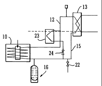
Referring now to Figs. 1 to 4, 6 and 7, a closed cycle heat transfer circuit
comprises an
evaporator in the form of a boiler 10 containing a heating coil 11 forming
part of the heat
transfer circuit. A first fluid duct 12 connects the output from the boiler 10
to a
condenser 13 which may be adapted, for example, to heat a working fluid in an
Organic
Rankine Cycle circuit 14. Thus, the condenser 13 acts as an evaporator for the
closed
circuit of the Organic Rankine Cycle. An air vent 9 is provided in duct 12 to
allow air to
be evacuated if necessary.
A second fluid duct 15 is connected to the condenser 13 to return condensate
to the
boiler 10.
Connected to the second fluid duct at a position close to the return entry
port to the
boiler 10 is an expansion device 16 which, as shown in Fig. 3, comprises a
vessel 17
divided internally into two enclosed separate chambers 18 and 19 by a flexible
membrane 20. The chamber 18 is in permanent communication with the duct 15. A
valved gas charging inlet 21 communicates with the chamber 19 for a purpose to
be
described.
In operation, the system is initially charged with, in this example, cold
water via an inlet
valve 22 into the fluid duct 15, to a pressure slightly in excess of
atmospheric pressure.
The gas pressure within the chamber 19 is established via inlet 21 at a higher
pressure
than that of the water in the circuit so that the membrane 20 is in the
position shown in
CA 02666321 2009-04-09
WO 2008/044008 PCT/GB2007/003837
Fig. 1. Thus, the expansion device 16 is filled with gas and contains little
or no water.
The pressure in the chamber 19 may be established initially at approximately 6
bar, then
reduced to around 1.5 bar.
5 As heat is applied within the boiler 10, for example by a gas flame, the
water initially
increases in temperature until it reaches the boiling point corresponding to
its pressure,
ie, 104 C for a pressure 1.2 bar absolute. Initially there is nowhere for the
generated
steam to expand and the pressure in the circuit will increase to around 1.5
bar, which is
more or less equivalent to the pressure established in the chamber 19 of the
expansion
device. As steam is generated and as the pressure in the first duct 12
increases, so
then the steam can start to fill a part of the boiler 10 and the duct 12. As
soon as the
steam space enters the condenser 13 heat is transferred from the duct 12 by
heat
exchange within the condenser, and as the heat continues to rise the steam
space
expands and the steam pressure rises, thus exposing more heat transfer area in
the
condenser 13.
As the fluid vapour phase in boiler 10, duct 12 and condenser 13 expands, so
the liquid
phase in duct 15 displaces the flexible membrane 20 in the expansion device 16
thus
compressing the gas in chamber 19 thereof as shown in Fig. 2. The compressed
gas
volume in chamber 19 therefore defines the pressure reached in the fluid
system such
that a defined relationship is achieved between the volume of fluid displaced
and the
pressure in the system.
Thus, the expansion vessel provides a mechanism to displace a variable volume
of
working fluid to form a vapour space in the system which enables the system to
be
entirely filled with the working fluid in liquid form when cold at a pressure
defined by the
characteristics of the expansion device 16.
It is intended that when the system is not operating the pressure therein
shall be at
atmospheric or slightly greater, thus avoiding a vacuum condition which could
encourage
the ingress of air or other non-condensable gases.
When the system is operating under elevated temperature, the pressure and
hence the
boiling temperature of the working fluid are determined by a combination of
the working
fluid saturation characteristics and the pressure/volume characteristics of
the expansion
device.
CA 02666321 2009-04-09
WO 2008/044008 PCT/GB2007/003837
6
Referring now to Fig. 4, in some cases at least one further condenser 23 may
be
provided and connected to the ducts 12 and 15 selectively by way of a valve
24. This
second condenser 23 may allow extra heat to be removed if the pressure in the
circuit
rises above a certain predetermined level, whereupon the valve 24 is to be
opened
automatically. Alternatively, this may be achieved by carefully selecting the
height of the
condenser 23 in relation to that of the boiler 10 and the condenser 13 so that
the
additional vapour space generated by the increased pressure starts to expose
the heat
transfer surface of the condenser 23 when the required pressure is reached.
The
expansion device 16 must be of such a size that sufficient steam space is
exposed in the
condenser 23 at the required pressure. Thus the top of the condenser 23 is
preferably
at or slightly above the level of the boiler and the bottom of the condenser
13. Thus,
with correct positioning of the heat exchangers, the valve 24 may be omitted.
In
operation, as the pressure rises then an increasing amount of heat exchanger
surface in
the condenser 23 is exposed, thus increasing the removal of heat and providing
a self-
regulating system.
A second, or even a third heat exchanger may be deployed for start-up or other
exceptional conditions where it is required to remove heat from the system but
not to
pass it to the condenser 13.
Referring now to Fig. 5, the physically closed loop circuit of Figs. 1, 2 and
4 may be
replaced by a so-called heat pipe in which a liquid-filled column 25 is heated
at its base
and useful heat is collected at its top. Within the column, heated liquid
passes upwardly
close to the wall of the column while cooled condensate passes downwardly
through the
central region, as the cycle continues.
In this embodiment also, an expansion device 26 similar to the expansion
device 16 is
connected to the column 25 thus to absorb excess fluid and leave adequate
space for
the increasing volume of the vapour phase as the heat increases.
Referring now to Fig. 6, if there is insufficient headroom to locate the
condenser 13 at a
sufficient height above the boiler 10 for a thermosyphon to operate, then a
pump 27 is
introduced into duct 15 to create a positive flow of condensate back into the
boiler 10.
CA 02666321 2009-04-09
WO 2008/044008 PCT/GB2007/003837
7
Referring now to Fig. 7, there is shown a heat transfer device connected to an
Organic
Rankine Cycle for supplying heat to a domestic CHP boiler (not shown). The
Organic
Rankine Cycle comprises the condenser 13 which serves also as an evaporator
for the
cycle, an expander 30, an economiser in the form a heat exchanger 31, a
condenser 32,
a pump 33 and heating circuit 34a, 34b.
In such a cycle the condensing steam in condenser 13 is used to evaporate an
organic
liquid in the duct 35 of the cycle. The vapour produced in duct 35 then drives
the
expander 30 thus producing power before the low pressure vapour is condensed
in
condenser 32 giving out its heat to the domestic heating system 34a, 34b, and
is then
pumped back by pump 33 to the evaporator circuit of condenser 13.
In this example, the additional heat exchanger or economiser 31 is used to
recover heat
from the hot vapour leaving the expander in order to pre-heat the liquid
leaving the pump
33 before it returns to the evaporator circuit of the condenser 13. As in the
embodiment
of Fig 4, when the Organic Rankine Cycle has taken as much heat as it is able
and the
heating system requires even further heat, then additional fuel is supplied to
the boiler
and the pressure will increase, thus causing valve 24 connected to additional
condenser
23 to open. The water which has been used to remove heat from the Organic
Rankine
Cycle can thus be used to remove additional heat from the condenser 23.
It will be seen that the use of an expansion device in a closed cycle heat
transfer device
of the kinds described, serves to take up the increase in volume of a liquid
as it boils,
creating a vapour space so that the heat transfer can take place effectively.
The
system, filled with liquid at a pressure just above atmospheric pressure when
the system
is cold, avoids the need for a vacuum pump or other special tools which would
be
needed prior to filling the system in order to remove any air or non-
condensing gas. The
system may be filled at or just above atmospheric pressure, and the expansion
device
will serve, in operation, to receive a proportion of the liquid, thus to
enable efficient
creation and deployment of the fluid vapour phase at the condenser.
It is not intended to limit the invention to the above specific description.
For example, a
liquid other than water can be used in the system, and the charging pressure
selected
according to the boiling temperature and saturation characteristics of the
liquid.
CA 02666321 2009-04-09
WO 2008/044008 PCT/GB2007/003837
8
In operation, equilibrium is achieved when sufficient temperature is attained
such that
the heat supplied by the boiler balances the heat taken up at the condenser.
In the case
of the heat pipe illustrated in Fig. 5 the liquid is likely to be a
refrigerant rather than
water.
The flexible membrane in the expansion devices 16 and 26 may be replaced by
any
other deformable or movable arrangement, such as a piston within a cylinder.
A number of advantages accrue from the provision of an expansion device in
such a
system, namely:
= the ability to charge a thermosyphon or similar heat transfer device in a
manner
which eliminates non-condensable gases such as air;
= the ability to charge such a device without the need for vacuum equipment
and
refrigeration engineering skills;
= the avoidance of vacuum condition when the device is not in use thus to
eliminate
ingress of air or other non-condensable gases;
= allowing the pressure/temperature operation defined by the working liquid
saturation characteristics to increase the available heat exchanger surface
area as
additional heat is transferred around the device;
= exploiting the relationship between temperature, pressure and system volume,
and
condensate level, to enable additional heat to be directed to additional
condensers
when required; and
= to provide a method of limiting the maximum pressure within the device by
directing excess heat to the heat exchange surface of an additional condenser
so
that equilibrium is reached for the maximum possible heat input.