Note: Descriptions are shown in the official language in which they were submitted.
CA 02666636 2009-04-16
WO 2008/051748 PCT/US2007/081392
Aseptic Structural Rib for Plastic Containers
BACKGROUND OF THE INVENTION
Field of the Invention
[0001] The present invention relates generally to aseptic structural ribs for
plastic containers, and more particularly to structural ribs that prevent
ovalization of a
plastic container and work with aseptic sterilization of the plastic container
formed by
blow molding.
Related Art
[0002] Conventional structural ribs for plastic containers may meet the
strength or structural requirement for a plastic container, but cause problems
in
sterilization of the resultant containers. In order for a plastic container to
be filled
with food product, an aseptic process is necessary. During this process, a
sterilizing
agent first must be introduced to all internal portions of the container and
then must
be removed in accordance with Food and Drug Administration (FDA) requirements.
Conventional structural ribs did not address both the structural and aseptic
needs of
the plastic container.
[0003] Consequently, known structural rib shapes or methods of forming
a plastic container with the same either provided sufficient rigidity for the
plastic
container but did not pass the FDA requirements for the aseptic process, or,
provided
structur=al ribs with a geometry that allowed the resultant container to pass
the FDA
r=equirements after the aseptic process, but failed to provided sufficient
rigidity or=
strength to the plastic container. As a result, known structural ribs cause a
number of
plastic containers to fail the aseptic process, or, result in plastic
containers filled with
food product that develop an undesirable ovalization of the container.
[0004] Known structural ribs for a plastic container employ a single
indentation toward the center of the plastic container. A single structural
rib does not
provide the necessary hoop strength or rigidity to pr=event ovalization and/or
compressing of the container side walls during vending. Deeper projections of
the
single structural rib were thought capable of providing the necessary
strength, but
failed to hold the shape of the plastic container during vending. That is, the
deeper
projections did not resist distortion.
[0005] What is needed then is an improved plastic container with at least
one structural rib that overcomes shortcomings of conventional solutions.
1
CA 02666636 2009-04-16
WO 2008/051748 PCT/US2007/081392
BRIEF SUIVINIARY OF THE INVENTION
[0006] In summary, a blow-molded plastic container was developed that
addressed the structural aspect (hoop strength or rigidity) of container=
performance
while balancing that with aseptic requirements to create a structural rib
geometry that
could be sterilized through the aseptic process. An embodiment of the plastic
container of the invention includes a neck with an opening, a bell portion
surrounding
the neck, a body portion including at least one "m"-shaped horizontal rib, and
a base
where the body portion is located between the bell portion and the base.
[0007] This invention succeeds where previous efforts have failed by
pr=oviding the additional structure that was needed about the container body
in order
to eliminate the container from ovalization. This was achieved by recognizing
that
increasing rib projections into the container caused problems with the
sterilizing
agent accessing the container underneath the projection and removal of the
sterilizing
agent accor-ding to FDA requirements. The aseptic process, therefore, was a
limiting
factor in how deep the rib could extend into the package. Thus, the solution
was to
change the profile of the rib so that the profile would be friendly to the
aseptic
process of sterilizing the interior of the container and still provide the
necessary hoop
strength or rigidity of the plastic container= that resists deflection of the
container= sides
during sidewall load, palletizing, or vending.
[0008] Another embodiment of the invention is a method of providing
hoop strength and sterility in a plastic container. This is achieved by blow
molding a
plastic container with a neck, bell portion, body portion and base forming an
interior,
providing the body portion with at least one "m"-shaped horizontal rib to
pr=ovide
sufficient hoop strength thereby eliminating ovalization of a plastic
container filled
with food product, sterilizing the plastic container with a sterilizing agent,
and
effectively removing the sterilizing agent wherein the shape of the "m"-shaped
horizontal rib provides sufficient structural strength while enabling the
sterilizing
agent to access all of the interior of the plastic container and enabling
effective
rei~oval of the sterilizing agent.
[0009] Further objectives and advantages, as well as the structure and
function of preferred embodiments will become apparent from a consideration of
the
description, drawings, and examples.
BRIEF DESCRIPTION OF THE DRAWINGS
2
CA 02666636 2009-04-16
WO 2008/051748 PCT/US2007/081392
[00010] The foregoing and other features and advantages of the invention
will be apparent from the following, more particular description of a
preferr'ed
embodiment of the invention, as illustrated in the accompanying drawings
wherein
like reference numbers generally indicate identical, functionally similar,
and/or=
structurally similar elements.
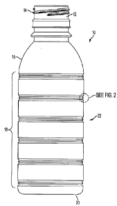
[00011] FIG. 1 depicts an exemplary embodiment of a plastic container
according to the present invention,.
[00012] FIG. 2 shows the dashed circled area of FIG. 1 enlarged in a detail
to illustrate the "m"-shaped horizontal rib according to one embodiment of the
present invention.
DETAILED DESCRIPTION OF THE INVENTION
[00013] Embodiments of the invention are discussed in detail below. In
describing embodiments, specific terminology is employed for= the sake of
clarity.
However, the invention is not intended to be limited to the specific
terminology so
selected. While specific exemplary embodiments are discussed, it should be
understood that this is done for illustration purposes only. A person skilled
in the
relevant art will recognize that other components and configurations can be
used
without parting from the spirit and scope of the invention.
[00014] Referring to Figure 1, a plastic container 10 according to an
exemplary embodiment of the invention is shown. The container 10 can be used
to
package a wide variety of liquid, viscous or solid products including, for
example,
juices, other beverages, yogurt, sauces, pudding, lotions, soaps in liquid or
gel form,
and bead shaped objects such as candy. The present container can be made by
conventional blow molding processes including, for example, extrusion blow
molding, stretch blow molding and injection blow molding.
[00015] Container 10 has a neck 12 that surrounds an opening to the
interior= of container 10. In this example, neck 12 has a finish 14 for
receiving a lid
that is not shown.. A bell portion 16 extends outwardly from the circumference
of
neck 12 to a body portion 18 where the bell portion 16 and body portion 18
form the
sidewalls of container 10. A base 20 is formed at the bottom ofbody portion
18. The
sidewalls of the container 10 determine the amount of volume for adding a
product to
the container 10.
3
CA 02666636 2009-04-16
WO 2008/051748 PCT/US2007/081392
[00016] The body portion 18 may include a number of structural ribs 22.
Each structural rib 22 circumscribes body portion 18 along a generally
horizontal
plane. The number of structur=al ribs needed to surround the body portion 18
to
pr=ovide sufficient hoop strength (i.e., resist deflection or distortion of
the sidewalls)
depends on several factors.. For example, the volume of the container (height
and
width of the body portion), the thickness of the plastic used to blow-molded
container
10, and the desired hoop strength to resist deflection of a filled container
as it is side
loaded, palletized or vended. As structural rib 22 extends around the body
portion, it
provides hoop strength or rigidity to the sidewalls ofbody portion 18 of
container 10.
That is, the generally horizontal structural rib 22 provides the necessary
hoop
strength so that sidewalls of container 10 resist deflection and do not become
compressed during sidewall loading, palletizing or vending.
[00017] The sidewalls, as formed, are substantially tubular and can have
any cross sectional shape. Cross sectional shapes include, for example, a
circular
transverse cross section; an oval transverse cross section; a substantially
square
tr=ansverse cross section; other substantially polygonal transverse cross
sectional
shapes such as triangular, pentagonal, etc.; or combinations of curved and
arced
shapes with linear shapes. As will be understood, when the container has a
substantially polygonal transverse cross sectional shape, the corners of the
polygon
are typically rounded or, chamfered.
[00018] Figure 2 shows the dashed circled area of FIG. 1 enlarged in a
detail to illustrate the "m"-shaped horizontal rib 22 according to one
embodiment of
the present invention. The "m"-shaped horizontal rib is a departure fr-om the
single
rib with a deeper projection into the container in order to meet the desired
hoop
strength while still maintaining quality control (containers passing the FDA
requirements for sterilization). The "m"-shaped horizontal rib 22 is formed
with two
rounded indentations 24 projecting into the center of the container on either
side of a
rounded bump 26 facing the opposite direction (i.e., away from the center of
the
container). It is this profile of the structural rib that provides sufficient
hoop strength
while allowing the sterilizing agent to be effectively removed in accordance
with
FDA requirements.
[00019] Indentations 24 are formed so that they are rounded at a vertical
plane tangent to or forming part of body portion 18 and projected toward the
center of
container 10 a distance before angling off to form the rounded indentation
24., In a
4
CA 02666636 2009-04-16
WO 2008/051748 PCT/US2007/081392
similar manner, although in the opposite direction and extending from the top
of
rounded indentation 24, the rounded bump 26 is formed between two indentations
24. However, rounded bump 26 does not extend to the vertical plane tangent to
or
forming part of body portion 18. Consequently, while indentations 24 project
into the
container, r-ounded bump 26 is less deep than a side of indention 24 which
projects
from the plane tangent to or forming part of body portion 18. That is, the
rounded
bump does not reach the plane tangent to or forming part of body portion 18,
as the
r=ounded bump 26 reaches a second plane closer to the center of container 10.
[00020] The profile of the "m"-shaped horizontal rib 22 allows the
sterilizing agent to access an underside of each indentation 24 and the
interior= of
rounded bump 26. In the same manner, a rinsing solution can effectively remove
the
sterilizing agent from all parts of the container 10 thereby reducing the
number of
rejected containers due to the aseptic process of sterilizing the container.
[00021] In an exemplary embodiment, the indentations 24 may project
into the container approximately .045 inch (1.13 mm). The foot of indentation
24
extending inwardly toward the center of the container from body portion 18 may
have
a radius of approximately.027 inch (0.67mm) where the indentation 24 after
being
rounded off of the vertical plane tangent to or forming part of body portion
18
extends about .034 inch (0.86 mm) to the rounded top of the indentation 24.
The
r=ounded top of indentation 24 may have a radius of .024 inch (0.60 mm). The
rounded bump 26 is blended between the two rounded indentations with an
rounded
top. The width of the "m"-shaped horizontal rib profile may be around õ 191
inch
(4.86 mm) with the tops of the rounded indentations 24 being.085 inch (2.17
mm),.
The radii of the rounded "m"-shaped horizontal rib vary depending upon the
size of
the rib, the thickness of the container plastic, etc. to create a consistent,
proportional
"m" style for containers of varying volumes, heights, etc.
[00022] The "m"-shaped horizontal rib 24 provides sufficient hoop
strength in a position or positions where rigidity does the most good,. That
is, at least
one "m"-shaped horizontal rib 22 is placed in a position along the body
portion 18 to
provide the strongest hoop strength to the plastic container 10. A container
10 may
have a plurality of "m"-shaped horizontal ribs 24 in order to prevent
ovalization,
which may occur due to a change in temperature of the filled container. The
change
in temperature could cause the sidewall of the container to pull in toward the
center of
the container presenting a non-aesthetic appear=ance. For example,
refrigerating a
5
CA 02666636 2009-04-16
WO 2008/051748 PCT/US2007/081392
liquid in a plastic container may contract the sidewalls that were originally
designed
to be round in appearance,. However, with the "m"-shaped horizontal rib
structure of
the exemplary invention, such a container can be provided with sufficient hoop
strength or rigidity to resist deflection due to changes in temperature or due
to
compression in side loading, palletizing or vending. That is, containers with
the "m"-
shaped horizontal rib or ribs according to the invention are vendable. The "m"-
shaped horizontal rib strengthens the sidewalls of a filled plastic container
to such a
degree that the filled container resists deflection in its sidewalls as it
moves through a
vending machine mazeõ
[000231 The plastic container 10 may include a shrink wrap film with a
label surrounding body portion 18,. The shrink film serves two purposes: 1) as
a
label; and 2) as a cover7ng over the "m"-shaped horizontal rib(s). The "m"-
shaped
horizontal rib keeps the shrink film from collapsing into the grooves of the
"m"-
styled indentions due to the rounded bump 26. Thus, the shrink film label is
not
wrinkled when placed on the container and aesthetically presents the product,
as well
as ensures that the ingredients, product name and other descriptive legends
are clearly
presented to the consumer.
[00024] The container according to another embodiment of the invention is
achieved through a blow molding process. A plastic container 10 is created
with a
neck 12, bell portion 16, body portion 18 and base 20 forming an interior,.
Body
portion 18 is provided with at least one "m"-shaped horizontal rib 22 that
increases
the hoop strength of the smooth body portion 18. The increased hoop strength
of
container 10 resists deflection of the plastic container that results in
ovalization or
another non-aesthetic appearance. Sterilization of the container 10 can be
achieved
by adding a sterilizing agent to the container so that it reaches all interior
portions of
the container and then, rinsing the sterilizing agent out of container 10. The
"m"-
shaped horizontal rib is designed so that it provides sufficient structural
hoop strength
while enabling the sterilizing agent to access all parts of the plastic
container interior
and effective removal of the sterilizing agent to FDA requirements,. That is,
the "m"-
shaped horizontal rib does not captur=e and retain microbes of the sterilizing
agent so
that the container fails the FDA requirements and the container is rejected.
[00025] The "m"-shaped horizontal rib 22 may be formed while the
container 10 is being blow molded. A generally horizontal "m"-shaped
horizontal rib
is formed about a perimeter of body portion 18 with two rounded indentations
24
6
CA 02666636 2009-04-16
WO 2008/051748 PCT/US2007/081392
pushed inward into the body portion 18 with a rounded bump 26 facing outward
between the two rounded indentations 24. The rounded indentations 24 extend on
one side from a first plane tangent to or forming part of body portion 18 and
the top
of the rounded bump 26 between the two rounded indentations reaches a second
plane
closer to the center of container 10.
[00026] The two rounded indentations 24 extend into container 10 a
smaller distance than a single indentation that may provide a similar hoop
strength.
Consequently, the two rounded indentations 24 of the exemplary invention do
not
have a deep underside into which sterilizing agent must frrst enter and then
be
effectively removed by a rinsing agent. That is, the "m"-shaped horizontal rib
is of a
shape that allows the sterilizing agent to access an underside of the rib 22
and that
enables the sterilizing agent to be effectively removed from the plastic
container 10
thereby decreasing the r=ejected containers after the aseptic process.
[00027] The embodiments illustrated and discussed in this specification are
intended only to teach those skilled in the art the best way known to the
inventors to
make and use the invention. Nothing in this specification should be considered
as
limiting the scope of the present invention. All examples presented are
representative
and non-limiting. The above-described embodiments of the invention may be
modified or varied, without departing fr=om the invention, as appreciated by
those
skilled in the art in light of the above teachings. It is therefore to be
understood that,
within the scope of the claims and their equivalents, the invention may be
practiced
otherwise than as specifically described.
7