Language selection

Search

Patent 2666729 Summary

Third-party information liability

Some of the information on this Web page has been provided by external sources. The Government of Canada is not responsible for the accuracy, reliability or currency of the information supplied by external sources. Users wishing to rely upon this information should consult directly with the source of the information. Content provided by external sources is not subject to official languages, privacy and accessibility requirements.

Claims and Abstract availability

Any discrepancies in the text and image of the Claims and Abstract are due to differing posting times. Text of the Claims and Abstract are posted:

  • At the time the application is open to public inspection;
  • At the time of issue of the patent (grant).
(12) Patent Application: (11) CA 2666729
(54) English Title: SLIDING-BOW TARPAULIN SYSTEM
(54) French Title: BACHE A ARCHES COULISSANTES
Status: Deemed Abandoned and Beyond the Period of Reinstatement - Pending Response to Notice of Disregarded Communication
Bibliographic Data
(51) International Patent Classification (IPC):
  • B60P 07/04 (2006.01)
(72) Inventors :
  • WENSING, UDO (Germany)
  • HAHNEN, HANS BORIS (Germany)
  • NEUMEYER, FRANK (Germany)
  • FRENTZEN, FRANK (Germany)
  • BIRKENBACH, ROLF (Germany)
  • KEMMERLING, KARL (Germany)
  • SCHOLZ, AXEL (Germany)
  • LAUTERBACH, TIM (Germany)
  • WEIGELT, ROLF (Germany)
(73) Owners :
  • VBG GROUP TRUCK EQUIPMENT GMBH
(71) Applicants :
  • VBG GROUP TRUCK EQUIPMENT GMBH (Germany)
(74) Agent: MARKS & CLERK
(74) Associate agent:
(45) Issued:
(22) Filed Date: 2009-05-25
(41) Open to Public Inspection: 2009-12-06
Availability of licence: N/A
Dedicated to the Public: N/A
(25) Language of filing: English

Patent Cooperation Treaty (PCT): No

(30) Application Priority Data:
Application No. Country/Territory Date
08010327 (European Patent Office (EPO)) 2008-06-06

Abstracts

English Abstract


The invention relates to a sliding-bow tarpaulin system
for lorries or lorry trailers, with a plurality of
runner and guide rails, which extend on the loading
area of the lorry along the longitudinal sides of the
loading area and in which roller carriages, with
retaining bow members that are positioned thereon and
are realized like portals, are displaceably guided, and
with a tarpaulin attached to the retaining bow members.
In order to provide a sliding-bow tarpaulin system,
where a tautening of the tarpaulin in the upper region
is possible, at least one of the retaining bow members,
in particular a retaining bow member that is not
realized so as to be displaceable and/or is provided at
one end of the loading area, is to be realized in its
bottom region so as to be tiltable about a pivotal
axis.


Claims

Note: Claims are shown in the official language in which they were submitted.

-6-
claims
1. Sliding-bow tarpaulin system (2) for lorries or
lorry trailers (1), with a plurality of runner and
guide rails (4), which extend on the loading area (3)
of the lorry or lorry trailer (1) along the
longitudinal sides of the loading area and in which
roller carriages (5), with retaining bow members (6)
that are positioned thereon and are realized like
portals, are displaceably guided, and with a tarpaulin
attached to the retaining bow members (6),
characterized in that at least one of the retaining bow
members (6), in particular a retaining bow member (6)
that is not realized so as to be displaceable and is
provided at one end of the loading area (3), is
realized in its bottom region so as to be tiltable
about a pivotal axis (10).
2. Sliding-bow tarpaulin system (2) according to
the preceding claim, characterized in that in the case
of at least one of the retaining bow members (6) that
is realized so as to be displaceable, the roller
carriage (5) has play in the guide rails (4) and
consequently enables tipping to a small extent.
3. Sliding-bow tarpaulin system (2) according to
the preceding claim, characterized in that in the case
of at least one of the retaining bow members (6) that
is realized so as to be displaceable, the roller
carriage (5) is realized so as to be fixedly securable,
in particular fixedly clampable or lockable, in at
least one position in the runner and guide rails (4).
4. Sliding-bow tarpaulin system (2) according to
one of the preceding claims, characterized in that the
securement of the tarpaulin to the retaining bow
members (6) has play, in particular ca. 1 cm or a few
cm.

-7-
5. Sliding-bow tarpaulin system (2) according to
one of the preceding claims, characterized in that the
retaining bow member (6) provided with a pivotal axis
(10) has a device (11) for obtaining a deflection
force, which effects a pivoting of the retaining bow
member (6), in particular in the direction opposing the
extension of the tarpaulin.
6. Sliding-bow tarpaulin system (2) according to
the preceding claim, characterized in that the device
(11) for obtaining a deflection force is realized as a
resilient element, in particular as a resilient element
exerting a compressive force, such as, for example, a
compression spring.
7. Sliding-bow tarpaulin system (2) according to
Claim 4 or 5, characterized in that the device (11) for
obtaining a deflection force is realized as a
displacement element that is in particular manually
actuatable, such as, for example an eccentric.
8. Sliding-bow tarpaulin system (2) according to
one of the preceding claims, characterized in that a
device (12) is provided for blocking the position of
the retaining bow member (6), such as, for example, a
few locking catches.
9. Sliding-bow tarpaulin system (2) according to
one of the preceding claims, characterized in that at
least one retaining bow member (6) is provided, in the
top region on at least one side, with an auxiliary bow
member (7) that in particular is pivotally secured, is
hingeable to the retaining bow member (6) and is
realized like a portal, the length of said auxiliary
bow member being realized such that its top transverse
strut in the opened out state is at least approximately
at the same level as the transverse strut of the
retaining bow member (6), on which it is positioned.

Description

Note: Descriptions are shown in the official language in which they were submitted.


CA 02666729 2009-05-25
SLIDING-BOW TARPAULIN SYSTEM
- 1 -
The invention relates to a sliding-bow tarpaulin system
for lorries or lorry trailers, with a plurality of
runner and guide rails, which extend on the loading
area of the lorry or lorry trailer along the
longitudinal sides of the loading area and in which
roller carriages, with retaining bow members that are
positioned thereon and are realized like portals, are
displaceably guided, and with a tarpaulin attached to
the retaining bow members.
Such sliding-bow tarpaulin systems are known in
practice and the majority are designed as described in
DE 198 39 820 Al.
In operation there is both the loaded and the unloaded
state and, on account of the different levels of load-
deflection of the loading area, the result is that the
top side of the tarpaulin is not tensioned tautly
enough and consequently, at least in part regions, sags
to a greater or lesser extent. This leads to adverse
effects, such as, for example, noise nuisance, through
flapping or similar when driving, and moisture can
collect on the tarpaulin and this then has to be
removed or can drop down at unsuitable moments. It is
even more critical in winter when this collected
moisture freezes and consequently falls to the ground
in the form of ice.
It is the object of the invention to avoid the
aforementioned disadvantages and to provide a sliding-
bow tarpaulin system where a tautening of the tarpaulin
in the top region is possible.
This object is achieved in that at least one of the
retaining bow members, in particular a retaining bow
member that is not realized so as to be displaceable
and/or is provided at one end of the loading area, is
realized in its bottom region so as to be tiltable

CA 02666729 2009-05-25
I~I
_ 2 _
about a pivotal axis. This means that a horizontal
displacement of the top region of said retaining bow
member is effected, which means that a tautening of the
top side of the tarpaulin can be effected, the bottom
region of the tarpaulin, i.e. the bottom region of the
lateral walls, is not influenced or is at least hardly
influenced.
In an advantageous manner, in the case of at least one
of the retaining bow members that is realized so as to
be displaceable, the roller carriage can be realized so
as to be fixedly securable, in particular fixedly
clampable or lockable, in at least one position in the
runner and guide rails, such that fixed positioning for
example at one or also both of the respective ends of
the loading area can be effected and the retaining bow
members provided there when the vehicle is being driven
are moveable away from this position for loading and/or
unloading procedures.
According to the invention, in the case of at least one
of the retaining bow members that is realized so as to
be displaceable, the roller carriage can have play in
the runner and guide rails and consequently can enable
tipping to a small extent, such that by tipping the
retaining bow member, a horizontal displacement of the
top region is likewise possible and consequently a
movement of the tarpaulin can be "entrained".
The securement of the tarpaulin to the retaining bow
'members can also have play for this purpose, in
particular ca. 1 cm or a few cm.
In an advantageous manner, the retaining bow member
provided with a pivotal axis can have a device for
obtaining a deflection force, which effects a pivoting
of the retaining bow member, in particular in the
direction opposing the extension of the tarpaulin, such
that the pivoting at least in one pivoting direction
, _ ,

CA 02666729 2009-05-25
- 3 -
does not have to be effected manually or by way of an
auxiliary means or tool.
In this case the device for obtaining a deflection
force can be realized as a resilient element, in
particular as a resilient element exerting a
compressive force, such as, for example, a compression
spring, such that a deflection is possible without an
additional power source, as would be necessary, for
example, for electric or pneumatic or respectively
hydraulic actuation.
The device for obtaining a deflection force can also be
realized as a displacement element that is in
particular manually actuatable, such as, for example,
an eccentric, which means that a simple, tool-free
actuation is possible.
In addition, a device can be provided for blocking the
position of the retaining bow member, such as, for
example, a few locking catches, such that an adjustable
tautening in the top region of the tarpaulin is also
effectable and, in particular, there is a possibility
for reducing the tension for displacing the retaining
bow member situated at the rear of the lorry or at the
end of the lorry trailer.
In an advantageous manner, at least one retaining bow
member can be provided, in the top region on at least
one side, with an auxiliary bow member that in
particular is pivotally secured, is hingeable to the
retaining bow member and is realized like a portal, the
length of said auxiliary bow member being realized such
that its top transverse strut in the opened out state
is at least approximately at the same level as the
transverse strut of the retaining bow member, on which
it is positioned, such that a better supporting of the
tarpaulin at a plurality of points is provided.

CA 02666729 2009-05-25
- 4 -
An exemplary embodiment of the invention represented in
the drawing is explained=below, in which:
Figure 1 shows a lorry trailer attached to a lorry
traction engine, said trailer having a
sliding-bow tarpaulin system according to the
invention, and
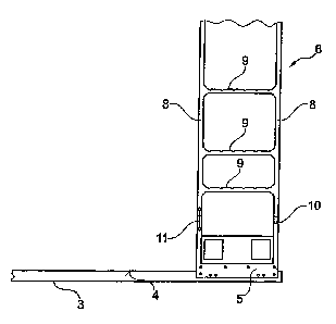
Figure 2 shows the detail "X" of the object in Figure
1.
Corresponding references are used in all the figures
for identical or respectively similar-type components.
Figure 1 shows a lorry trailer 1 with a sliding-bow
tarpaulin system 2 with a plurality of runner and guide
rails 4 that extend on the loading area 3 of the lorry
trailer 1 along the longitudinal sides of the loading
area 3. Roller carriages 5 with retaining bow members
6, which are positioned thereon and are realized like
portals, are displaceably guided in the runner and
guide rails 4, the retaining bow members 6, in the top
region on both sides, each being provided with an
auxiliary bow member 7, which is pivotally secured and
realized like a portal, said auxiliary bow members
being hingeable to the respective retaining bow member
6. The retaining and auxiliary bow members 6, 7
consequently span the width of the loading area 3 and,
by means of their roller carriages 5, are positioned so
as to be displaceable in the runner and guide rails 4.
The length of the auxiliary bow member 7, in this case,
is developed such that its top transverse strut 7a, in
the opened state, is at least approximately at the same
height as the transverse strut 6a of that retaining bow
member 6, on which the auxiliary bow member 7 is
positioned.

CA 02666729 2009-05-25
- 5 -
The sliding-bow tarpaulin system 2 additionally
includes a tarpaulin that is attached in the
conventional manner to the retaining bow members 6 and
the auxiliary bow members 7, said tarpaulin not being
represented in the drawing for reasons of better
clarity.
The retaining bow members 6 provided respectively at
the front or respectively the rear end of the loading
area 3 are realized here as end bow members, which,
when viewed from the side, have a ladder-like design
with two vertical struts 8 positioned spaced apart and
extending perpendicularly in the runner and guide rails
4 and a plurality of said vertical struts 8 having
horizontally interconnecting horizontal struts 9.
In order to enable a targeted tensioning of the
tarpaulin substantially at its top side, the end bow
member provided at the end of the lorry trailer 1 is
realized in its bottom region so as to be tiltable
about a pivotal axis 10.
The roller carriage 5 of said end bow member, in this
case, is realized so as to be fixedly securable, in
particular fixedly clampable or lockable, in at least
this end position in the runner and guide rails.
In addition, said end bow member has a device 11 for
obtaining a deflection force, which effects a pivoting
of the retaining bow member into the direction opposing
the extension of the tarpaulin, i.e. away from the
traction engine towards the end of the lorry trailer,
about the pivotal axis 10.
In this case, the device 11 for obtaining a deflection
force is realized as a resilient element that exerts a
compressive force, such as, for example, a compression
spring and a device 12 is provided for blocking the
pivoted position of the retaining bow member.

Representative Drawing
A single figure which represents the drawing illustrating the invention.
Administrative Status

2024-08-01:As part of the Next Generation Patents (NGP) transition, the Canadian Patents Database (CPD) now contains a more detailed Event History, which replicates the Event Log of our new back-office solution.

Please note that "Inactive:" events refers to events no longer in use in our new back-office solution.

For a clearer understanding of the status of the application/patent presented on this page, the site Disclaimer , as well as the definitions for Patent , Event History , Maintenance Fee  and Payment History  should be consulted.

Event History

Description Date
Application Not Reinstated by Deadline 2013-05-27
Time Limit for Reversal Expired 2013-05-27
Deemed Abandoned - Failure to Respond to Maintenance Fee Notice 2012-05-25
Amendment Received - Voluntary Amendment 2011-04-21
Amendment Received - Voluntary Amendment 2010-08-23
Inactive: Cover page published 2009-12-06
Application Published (Open to Public Inspection) 2009-12-06
Inactive: First IPC assigned 2009-10-01
Inactive: IPC assigned 2009-10-01
Inactive: Filing certificate - No RFE (English) 2009-06-15
Application Received - Regular National 2009-06-15
Amendment Received - Voluntary Amendment 2009-05-25

Abandonment History

Abandonment Date Reason Reinstatement Date
2012-05-25

Maintenance Fee

The last payment was received on 2011-04-08

Note : If the full payment has not been received on or before the date indicated, a further fee may be required which may be one of the following

  • the reinstatement fee;
  • the late payment fee; or
  • additional fee to reverse deemed expiry.

Patent fees are adjusted on the 1st of January every year. The amounts above are the current amounts if received by December 31 of the current year.
Please refer to the CIPO Patent Fees web page to see all current fee amounts.

Fee History

Fee Type Anniversary Year Due Date Paid Date
Application fee - standard 2009-05-25
MF (application, 2nd anniv.) - standard 02 2011-05-25 2011-04-08
Owners on Record

Note: Records showing the ownership history in alphabetical order.

Current Owners on Record
VBG GROUP TRUCK EQUIPMENT GMBH
Past Owners on Record
AXEL SCHOLZ
FRANK FRENTZEN
FRANK NEUMEYER
HANS BORIS HAHNEN
KARL KEMMERLING
ROLF BIRKENBACH
ROLF WEIGELT
TIM LAUTERBACH
UDO WENSING
Past Owners that do not appear in the "Owners on Record" listing will appear in other documentation within the application.
Documents

To view selected files, please enter reCAPTCHA code :


To view images, click a link in the Document Description column (Temporarily unavailable). To download the documents, select one or more checkboxes in the first column and then click the "Download Selected in PDF format (Zip Archive)" or the "Download Selected as Single PDF" button.

List of published and non-published patent-specific documents on the CPD .

If you have any difficulty accessing content, you can call the Client Service Centre at 1-866-997-1936 or send them an e-mail at CIPO Client Service Centre.

({010=All Documents, 020=As Filed, 030=As Open to Public Inspection, 040=At Issuance, 050=Examination, 060=Incoming Correspondence, 070=Miscellaneous, 080=Outgoing Correspondence, 090=Payment})


Document
Description 
Date
(yyyy-mm-dd) 
Number of pages   Size of Image (KB) 
Description 2009-05-24 5 210
Abstract 2009-05-24 1 20
Drawings 2009-05-24 2 26
Claims 2009-05-24 2 81
Representative drawing 2009-11-09 1 4
Filing Certificate (English) 2009-06-14 1 157
Reminder of maintenance fee due 2011-01-25 1 112
Courtesy - Abandonment Letter (Maintenance Fee) 2012-07-19 1 174
Prosecution correspondence 2009-05-24 1 45