Sélection de la langue

Search

Sommaire du brevet 2666729 

Énoncé de désistement de responsabilité concernant l'information provenant de tiers

Une partie des informations de ce site Web a été fournie par des sources externes. Le gouvernement du Canada n'assume aucune responsabilité concernant la précision, l'actualité ou la fiabilité des informations fournies par les sources externes. Les utilisateurs qui désirent employer cette information devraient consulter directement la source des informations. Le contenu fourni par les sources externes n'est pas assujetti aux exigences sur les langues officielles, la protection des renseignements personnels et l'accessibilité.

Disponibilité de l'Abrégé et des Revendications

L'apparition de différences dans le texte et l'image des Revendications et de l'Abrégé dépend du moment auquel le document est publié. Les textes des Revendications et de l'Abrégé sont affichés :

  • lorsque la demande peut être examinée par le public;
  • lorsque le brevet est émis (délivrance).
(12) Demande de brevet: (11) CA 2666729
(54) Titre français: BACHE A ARCHES COULISSANTES
(54) Titre anglais: SLIDING-BOW TARPAULIN SYSTEM
Statut: Réputée abandonnée et au-delà du délai pour le rétablissement - en attente de la réponse à l’avis de communication rejetée
Données bibliographiques
(51) Classification internationale des brevets (CIB):
  • B60P 07/04 (2006.01)
(72) Inventeurs :
  • WENSING, UDO (Allemagne)
  • HAHNEN, HANS BORIS (Allemagne)
  • NEUMEYER, FRANK (Allemagne)
  • FRENTZEN, FRANK (Allemagne)
  • BIRKENBACH, ROLF (Allemagne)
  • KEMMERLING, KARL (Allemagne)
  • SCHOLZ, AXEL (Allemagne)
  • LAUTERBACH, TIM (Allemagne)
  • WEIGELT, ROLF (Allemagne)
(73) Titulaires :
  • VBG GROUP TRUCK EQUIPMENT GMBH
(71) Demandeurs :
  • VBG GROUP TRUCK EQUIPMENT GMBH (Allemagne)
(74) Agent: MARKS & CLERK
(74) Co-agent:
(45) Délivré:
(22) Date de dépôt: 2009-05-25
(41) Mise à la disponibilité du public: 2009-12-06
Licence disponible: S.O.
Cédé au domaine public: S.O.
(25) Langue des documents déposés: Anglais

Traité de coopération en matière de brevets (PCT): Non

(30) Données de priorité de la demande:
Numéro de la demande Pays / territoire Date
08010327 (Office Européen des Brevets (OEB)) 2008-06-06

Abrégés

Abrégé anglais


The invention relates to a sliding-bow tarpaulin system
for lorries or lorry trailers, with a plurality of
runner and guide rails, which extend on the loading
area of the lorry along the longitudinal sides of the
loading area and in which roller carriages, with
retaining bow members that are positioned thereon and
are realized like portals, are displaceably guided, and
with a tarpaulin attached to the retaining bow members.
In order to provide a sliding-bow tarpaulin system,
where a tautening of the tarpaulin in the upper region
is possible, at least one of the retaining bow members,
in particular a retaining bow member that is not
realized so as to be displaceable and/or is provided at
one end of the loading area, is to be realized in its
bottom region so as to be tiltable about a pivotal
axis.

Revendications

Note : Les revendications sont présentées dans la langue officielle dans laquelle elles ont été soumises.


-6-
claims
1. Sliding-bow tarpaulin system (2) for lorries or
lorry trailers (1), with a plurality of runner and
guide rails (4), which extend on the loading area (3)
of the lorry or lorry trailer (1) along the
longitudinal sides of the loading area and in which
roller carriages (5), with retaining bow members (6)
that are positioned thereon and are realized like
portals, are displaceably guided, and with a tarpaulin
attached to the retaining bow members (6),
characterized in that at least one of the retaining bow
members (6), in particular a retaining bow member (6)
that is not realized so as to be displaceable and is
provided at one end of the loading area (3), is
realized in its bottom region so as to be tiltable
about a pivotal axis (10).
2. Sliding-bow tarpaulin system (2) according to
the preceding claim, characterized in that in the case
of at least one of the retaining bow members (6) that
is realized so as to be displaceable, the roller
carriage (5) has play in the guide rails (4) and
consequently enables tipping to a small extent.
3. Sliding-bow tarpaulin system (2) according to
the preceding claim, characterized in that in the case
of at least one of the retaining bow members (6) that
is realized so as to be displaceable, the roller
carriage (5) is realized so as to be fixedly securable,
in particular fixedly clampable or lockable, in at
least one position in the runner and guide rails (4).
4. Sliding-bow tarpaulin system (2) according to
one of the preceding claims, characterized in that the
securement of the tarpaulin to the retaining bow
members (6) has play, in particular ca. 1 cm or a few
cm.

-7-
5. Sliding-bow tarpaulin system (2) according to
one of the preceding claims, characterized in that the
retaining bow member (6) provided with a pivotal axis
(10) has a device (11) for obtaining a deflection
force, which effects a pivoting of the retaining bow
member (6), in particular in the direction opposing the
extension of the tarpaulin.
6. Sliding-bow tarpaulin system (2) according to
the preceding claim, characterized in that the device
(11) for obtaining a deflection force is realized as a
resilient element, in particular as a resilient element
exerting a compressive force, such as, for example, a
compression spring.
7. Sliding-bow tarpaulin system (2) according to
Claim 4 or 5, characterized in that the device (11) for
obtaining a deflection force is realized as a
displacement element that is in particular manually
actuatable, such as, for example an eccentric.
8. Sliding-bow tarpaulin system (2) according to
one of the preceding claims, characterized in that a
device (12) is provided for blocking the position of
the retaining bow member (6), such as, for example, a
few locking catches.
9. Sliding-bow tarpaulin system (2) according to
one of the preceding claims, characterized in that at
least one retaining bow member (6) is provided, in the
top region on at least one side, with an auxiliary bow
member (7) that in particular is pivotally secured, is
hingeable to the retaining bow member (6) and is
realized like a portal, the length of said auxiliary
bow member being realized such that its top transverse
strut in the opened out state is at least approximately
at the same level as the transverse strut of the
retaining bow member (6), on which it is positioned.

Description

Note : Les descriptions sont présentées dans la langue officielle dans laquelle elles ont été soumises.

CA 02666729 2009-05-25
SLIDING-BOW TARPAULIN SYSTEM
- 1 -
The invention relates to a sliding-bow tarpaulin system
for lorries or lorry trailers, with a plurality of
runner and guide rails, which extend on the loading
area of the lorry or lorry trailer along the
longitudinal sides of the loading area and in which
roller carriages, with retaining bow members that are
positioned thereon and are realized like portals, are
displaceably guided, and with a tarpaulin attached to
the retaining bow members.
Such sliding-bow tarpaulin systems are known in
practice and the majority are designed as described in
DE 198 39 820 Al.
In operation there is both the loaded and the unloaded
state and, on account of the different levels of load-
deflection of the loading area, the result is that the
top side of the tarpaulin is not tensioned tautly
enough and consequently, at least in part regions, sags
to a greater or lesser extent. This leads to adverse
effects, such as, for example, noise nuisance, through
flapping or similar when driving, and moisture can
collect on the tarpaulin and this then has to be
removed or can drop down at unsuitable moments. It is
even more critical in winter when this collected
moisture freezes and consequently falls to the ground
in the form of ice.
It is the object of the invention to avoid the
aforementioned disadvantages and to provide a sliding-
bow tarpaulin system where a tautening of the tarpaulin
in the top region is possible.
This object is achieved in that at least one of the
retaining bow members, in particular a retaining bow
member that is not realized so as to be displaceable
and/or is provided at one end of the loading area, is
realized in its bottom region so as to be tiltable

CA 02666729 2009-05-25
I~I
_ 2 _
about a pivotal axis. This means that a horizontal
displacement of the top region of said retaining bow
member is effected, which means that a tautening of the
top side of the tarpaulin can be effected, the bottom
region of the tarpaulin, i.e. the bottom region of the
lateral walls, is not influenced or is at least hardly
influenced.
In an advantageous manner, in the case of at least one
of the retaining bow members that is realized so as to
be displaceable, the roller carriage can be realized so
as to be fixedly securable, in particular fixedly
clampable or lockable, in at least one position in the
runner and guide rails, such that fixed positioning for
example at one or also both of the respective ends of
the loading area can be effected and the retaining bow
members provided there when the vehicle is being driven
are moveable away from this position for loading and/or
unloading procedures.
According to the invention, in the case of at least one
of the retaining bow members that is realized so as to
be displaceable, the roller carriage can have play in
the runner and guide rails and consequently can enable
tipping to a small extent, such that by tipping the
retaining bow member, a horizontal displacement of the
top region is likewise possible and consequently a
movement of the tarpaulin can be "entrained".
The securement of the tarpaulin to the retaining bow
'members can also have play for this purpose, in
particular ca. 1 cm or a few cm.
In an advantageous manner, the retaining bow member
provided with a pivotal axis can have a device for
obtaining a deflection force, which effects a pivoting
of the retaining bow member, in particular in the
direction opposing the extension of the tarpaulin, such
that the pivoting at least in one pivoting direction
, _ ,

CA 02666729 2009-05-25
- 3 -
does not have to be effected manually or by way of an
auxiliary means or tool.
In this case the device for obtaining a deflection
force can be realized as a resilient element, in
particular as a resilient element exerting a
compressive force, such as, for example, a compression
spring, such that a deflection is possible without an
additional power source, as would be necessary, for
example, for electric or pneumatic or respectively
hydraulic actuation.
The device for obtaining a deflection force can also be
realized as a displacement element that is in
particular manually actuatable, such as, for example,
an eccentric, which means that a simple, tool-free
actuation is possible.
In addition, a device can be provided for blocking the
position of the retaining bow member, such as, for
example, a few locking catches, such that an adjustable
tautening in the top region of the tarpaulin is also
effectable and, in particular, there is a possibility
for reducing the tension for displacing the retaining
bow member situated at the rear of the lorry or at the
end of the lorry trailer.
In an advantageous manner, at least one retaining bow
member can be provided, in the top region on at least
one side, with an auxiliary bow member that in
particular is pivotally secured, is hingeable to the
retaining bow member and is realized like a portal, the
length of said auxiliary bow member being realized such
that its top transverse strut in the opened out state
is at least approximately at the same level as the
transverse strut of the retaining bow member, on which
it is positioned, such that a better supporting of the
tarpaulin at a plurality of points is provided.

CA 02666729 2009-05-25
- 4 -
An exemplary embodiment of the invention represented in
the drawing is explained=below, in which:
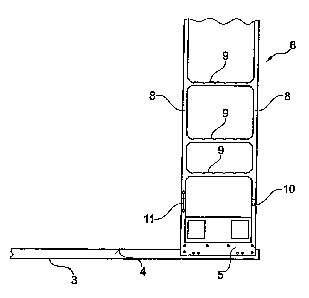
Figure 1 shows a lorry trailer attached to a lorry
traction engine, said trailer having a
sliding-bow tarpaulin system according to the
invention, and
Figure 2 shows the detail "X" of the object in Figure
1.
Corresponding references are used in all the figures
for identical or respectively similar-type components.
Figure 1 shows a lorry trailer 1 with a sliding-bow
tarpaulin system 2 with a plurality of runner and guide
rails 4 that extend on the loading area 3 of the lorry
trailer 1 along the longitudinal sides of the loading
area 3. Roller carriages 5 with retaining bow members
6, which are positioned thereon and are realized like
portals, are displaceably guided in the runner and
guide rails 4, the retaining bow members 6, in the top
region on both sides, each being provided with an
auxiliary bow member 7, which is pivotally secured and
realized like a portal, said auxiliary bow members
being hingeable to the respective retaining bow member
6. The retaining and auxiliary bow members 6, 7
consequently span the width of the loading area 3 and,
by means of their roller carriages 5, are positioned so
as to be displaceable in the runner and guide rails 4.
The length of the auxiliary bow member 7, in this case,
is developed such that its top transverse strut 7a, in
the opened state, is at least approximately at the same
height as the transverse strut 6a of that retaining bow
member 6, on which the auxiliary bow member 7 is
positioned.

CA 02666729 2009-05-25
- 5 -
The sliding-bow tarpaulin system 2 additionally
includes a tarpaulin that is attached in the
conventional manner to the retaining bow members 6 and
the auxiliary bow members 7, said tarpaulin not being
represented in the drawing for reasons of better
clarity.
The retaining bow members 6 provided respectively at
the front or respectively the rear end of the loading
area 3 are realized here as end bow members, which,
when viewed from the side, have a ladder-like design
with two vertical struts 8 positioned spaced apart and
extending perpendicularly in the runner and guide rails
4 and a plurality of said vertical struts 8 having
horizontally interconnecting horizontal struts 9.
In order to enable a targeted tensioning of the
tarpaulin substantially at its top side, the end bow
member provided at the end of the lorry trailer 1 is
realized in its bottom region so as to be tiltable
about a pivotal axis 10.
The roller carriage 5 of said end bow member, in this
case, is realized so as to be fixedly securable, in
particular fixedly clampable or lockable, in at least
this end position in the runner and guide rails.
In addition, said end bow member has a device 11 for
obtaining a deflection force, which effects a pivoting
of the retaining bow member into the direction opposing
the extension of the tarpaulin, i.e. away from the
traction engine towards the end of the lorry trailer,
about the pivotal axis 10.
In this case, the device 11 for obtaining a deflection
force is realized as a resilient element that exerts a
compressive force, such as, for example, a compression
spring and a device 12 is provided for blocking the
pivoted position of the retaining bow member.

Dessin représentatif
Une figure unique qui représente un dessin illustrant l'invention.
États administratifs

2024-08-01 : Dans le cadre de la transition vers les Brevets de nouvelle génération (BNG), la base de données sur les brevets canadiens (BDBC) contient désormais un Historique d'événement plus détaillé, qui reproduit le Journal des événements de notre nouvelle solution interne.

Veuillez noter que les événements débutant par « Inactive : » se réfèrent à des événements qui ne sont plus utilisés dans notre nouvelle solution interne.

Pour une meilleure compréhension de l'état de la demande ou brevet qui figure sur cette page, la rubrique Mise en garde , et les descriptions de Brevet , Historique d'événement , Taxes périodiques et Historique des paiements devraient être consultées.

Historique d'événement

Description Date
Demande non rétablie avant l'échéance 2013-05-27
Le délai pour l'annulation est expiré 2013-05-27
Réputée abandonnée - omission de répondre à un avis sur les taxes pour le maintien en état 2012-05-25
Modification reçue - modification volontaire 2011-04-21
Modification reçue - modification volontaire 2010-08-23
Inactive : Page couverture publiée 2009-12-06
Demande publiée (accessible au public) 2009-12-06
Inactive : CIB en 1re position 2009-10-01
Inactive : CIB attribuée 2009-10-01
Inactive : Certificat de dépôt - Sans RE (Anglais) 2009-06-15
Demande reçue - nationale ordinaire 2009-06-15
Modification reçue - modification volontaire 2009-05-25

Historique d'abandonnement

Date d'abandonnement Raison Date de rétablissement
2012-05-25

Taxes périodiques

Le dernier paiement a été reçu le 2011-04-08

Avis : Si le paiement en totalité n'a pas été reçu au plus tard à la date indiquée, une taxe supplémentaire peut être imposée, soit une des taxes suivantes :

  • taxe de rétablissement ;
  • taxe pour paiement en souffrance ; ou
  • taxe additionnelle pour le renversement d'une péremption réputée.

Les taxes sur les brevets sont ajustées au 1er janvier de chaque année. Les montants ci-dessus sont les montants actuels s'ils sont reçus au plus tard le 31 décembre de l'année en cours.
Veuillez vous référer à la page web des taxes sur les brevets de l'OPIC pour voir tous les montants actuels des taxes.

Historique des taxes

Type de taxes Anniversaire Échéance Date payée
Taxe pour le dépôt - générale 2009-05-25
TM (demande, 2e anniv.) - générale 02 2011-05-25 2011-04-08
Titulaires au dossier

Les titulaires actuels et antérieures au dossier sont affichés en ordre alphabétique.

Titulaires actuels au dossier
VBG GROUP TRUCK EQUIPMENT GMBH
Titulaires antérieures au dossier
AXEL SCHOLZ
FRANK FRENTZEN
FRANK NEUMEYER
HANS BORIS HAHNEN
KARL KEMMERLING
ROLF BIRKENBACH
ROLF WEIGELT
TIM LAUTERBACH
UDO WENSING
Les propriétaires antérieurs qui ne figurent pas dans la liste des « Propriétaires au dossier » apparaîtront dans d'autres documents au dossier.
Documents

Pour visionner les fichiers sélectionnés, entrer le code reCAPTCHA :


Pour visualiser une image, cliquer sur un lien dans la colonne description du document (Temporairement non-disponible). Pour télécharger l'image (les images), cliquer l'une ou plusieurs cases à cocher dans la première colonne et ensuite cliquer sur le bouton "Télécharger sélection en format PDF (archive Zip)" ou le bouton "Télécharger sélection (en un fichier PDF fusionné)".

Liste des documents de brevet publiés et non publiés sur la BDBC .

Si vous avez des difficultés à accéder au contenu, veuillez communiquer avec le Centre de services à la clientèle au 1-866-997-1936, ou envoyer un courriel au Centre de service à la clientèle de l'OPIC.

({010=Tous les documents, 020=Au moment du dépôt, 030=Au moment de la mise à la disponibilité du public, 040=À la délivrance, 050=Examen, 060=Correspondance reçue, 070=Divers, 080=Correspondance envoyée, 090=Paiement})


Description du
Document 
Date
(aaaa-mm-jj) 
Nombre de pages   Taille de l'image (Ko) 
Description 2009-05-24 5 210
Abrégé 2009-05-24 1 20
Dessins 2009-05-24 2 26
Revendications 2009-05-24 2 81
Dessin représentatif 2009-11-09 1 4
Certificat de dépôt (anglais) 2009-06-14 1 157
Rappel de taxe de maintien due 2011-01-25 1 112
Courtoisie - Lettre d'abandon (taxe de maintien en état) 2012-07-19 1 174
Correspondance de la poursuite 2009-05-24 1 45