Note: Descriptions are shown in the official language in which they were submitted.
CA 02666774 2009-05-22
MOULDING ASSEMBLY
[0001] The present invention claims priority to United States Provisional
Application No.
61/055,324, filed May 22, 2008, the contents of which are incorporated herein
by reference in
their entirety.
FIELD OF THE INVENTION
[0002] The present embodiments relate generally to a moulding assembly, such
as a
crown moulding assembly or chair rail moulding assembly, that provides
decorative
enhancement to a wall or ceiling surface.
BACKGROUND
[00031 Interior decorative mouldings, such as crown mouldings, door and window
casings, chair rails, baseboards, etc., are commonly used in the construction
industry. Typically
these mouldings have a flat surface on one side to mount flush against an
interior wall surface,
and a decorative surface on the opposite, exposed side. The visually appealing
decorative surface
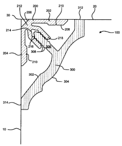
is usually formed in three dimensions.
[0004] One conventional type of moulding is an elongated structure, such as
one made of
wood or extruded material. This moulding typically has a uniform cross-
sectional profile created
by milling the decorative design into one surface of the material, or in the
case of extruded
plastic moulding, by extruding through a uniform profile die.
[0005] Crown moulding typically is manufactured in long sections for
installation by a
carpenter who miter cuts the moulding into sections, and fastens the moulding
directly to the
wall or ceiling surface. Installation of the crown moulding in this way,
however, can create
undesirable visible defects. For example, improper fastening of the moulding
trim portion can
damage the trim surface. In addition, in applications where the wall and
ceiling surfaces are not
flat or square, it may be difficult to install the crown moulding so that it
appears level and flush
with the wall and ceiling surfaces- the installed crown moulding may appear
uneven,
undesirably accentuating the imperfections in the underlying structures.
CA 02666774 2009-05-22
[0006] The description herein of certain advantages and disadvantages of known
methods
and devices is not intended to limit the scope of the present invention.
Indeed, the present
embodiments may include some or all of the features described above without
suffering from the
same disadvantages.
SUMMARY
[0007] In view of the foregoing, one or more embodiments described herein
provide a
moulding or trim assembly that has a retainer coupled with a removable trim
member. The
moulding or trim assembly can improve the ease of installation of the moulding
assembly, when
compared to traditional moulding assemblies. In addition, the trim member can
be removable
and replaceable, enabling design flexibility.
[0008] In one embodiment, a moulding assembly has a retainer and a trim
member. The
retainer has a central section, a first mounting leg extending from a first
end of the central
section, and a second mounting leg extending from a second end of the central
section. A first
fastening component is disposed at least partially on the central section of
the retainer. The trim
member includes a second fastening component that couples with the first
fastening component.
[0009] In another embodiment, a moulding assembly has an elongated retainer,
an
elongated trim member, and an elongated fastener assembly that couples the
trim member with
the retainer. The elongated retainer has a central section, a first mounting
leg extending from
said central section in a first plane, and a second mounting leg extending
from the central section
in a second plane that is substantially orthogonal to the first plane.
BRIEF DESCRIPTION OF THE DRAWINGS
[0010] Purposes and advantages of the exemplary embodiments will be apparent
to those
of ordinary skill in the art from the following detailed description in
conjunction with the
drawing figures in which like reference characters are used to indicate like
elements, in which:
[0011] Figure 1 is a cross-sectional view of a moulding assembly according to
an
exemplary embodiment described herein;
2
CA 02666774 2009-05-22
100121 Figure 2 is a cross-sectional view of an elongated trim member
according to an
exemplary embodiment;
[0013] Figure 3 is a cross-sectional view of an elongated retainer according
to an
exemplary embodiment;
100141 Figure 4 is a cross-sectional view of a moulding assembly according to
an
exemplary embodiment described herein;
[0015] Figure 5A is a cross-sectional view of a trim member and retainer of a
moulding
assembly according to an exemplary embodiment described herein;
[0016] Figure 5B is a cross-sectional view of a trim member and retainer of a
moulding
assembly according to an exemplary embodiment described herein;
[0017] Figure 5C is a cross-sectional view of a trim member and retainer of a
moulding
assembly according to an exemplary embodiment described herein; and
100181 Figure 5D is a cross-sectional view of a trim member and retainer of a
moulding
assembly according to an exemplary embodiment described herein.
DETAILED DESCRIPTION OF EXEMPLARY EMBODIMENTS
[0019] The following description is intended to convey a thorough
understanding of the
embodiments by providing a number of specific embodiments and details
involving a moulding
assembly. It is understood, however, that the invention is not limited to
these specific
embodiments and details, which are exemplary only. One possessing ordinary
skill in the art, in
light of known devices, systems and methods, would appreciate the use of the
invention for its
intended purposes and benefits in any number of alternative embodiments.
[0020] Generally speaking, the moulding assemblies of the various exemplary
embodiments described herein have an elongated retainer and an elongated trim
member. The
retainer may be fastened to one or more mounting surfaces, such as, for
example, a wall or a
ceiling surface. The retainer and trim member have mating mounting components
by which the
3
CA 02666774 2009-05-22
trim member may be removably coupled with the retainer. The two-piece moulding
assembly
may be easier to install than traditional moulding because it is more
forgiving of imperfections of
the underlying mounting surfaces, and it may provide an improved fit against
the mounting
surfaces with reduced or no gapping around the edges. The removable trim
member may be
interchangeable with other trim members, providing flexibility in design
options. In addition, the
trim member may be removed for ease of painting an underlying wall or ceiling
surface without
the need to tape off the trim member.
[0021] The various exemplary embodiment generally describe devices suitable
for crown
moulding trim applications, i.e., those hung in the upper corner of a room.
However, the
embodiments are not so limited. In various embodiments, the moulding assembly
may be
adapted for other trim applications, such as, for example, chair rail trim,
baseboard trim, door or
window trim applications, or other moulding or trim applications. In other
exemplary
embodiments, the moulding assembly may be suitable for use in exterior
applications, such as
siding applications. Upon review of the description provided herein, it will
be apparent how to
adapt the embodiments to other applications.
[0022] Referring now to FIGS. 1 and 4, in an exemplary embodiment, the
moulding
assembly 100 may trim an upper conrner 30 of a room at the intersection of
ceiling 20 and vertical
wall 10. In exemplary embodiments, moulding assembly 100 may include an
elongated retainer
200 and elongated trim member 300. Retainer 200 may be attached to a mounting
surface. For
example, the elongated retainer 200 may extend across the corner 30, fastening
to the interior
surfaces of wal110 and ceiling 20. In exemplary embodiments, the elongated
trim member 300
may be operably coupled with the retainer 200, extending along the length of
the retainer 200
and hiding the retainer 200 from view. In exemplary embodiments, the elongated
trim member
300 is not fastened directly to the wall 10 or ceiling 20, and may be
removable from the retainer
200. Various exemplary features of the retainer 200 and trim member 300 are
described below.
[0023] In exemplary embodiments retainer 200 and trim member 300 may be made
of
wood, metal, molded or extruded plastic, composite material, or other suitable
material. In
exemplary embodiments, the retainer 200 and trim member 300 may have a uniform
cross
4
CA 02666774 2009-05-22
section along their respective lengths. The outer surface 304 of trim member
300 may be
configured to have a decorative shape, so as to present an ornamental
appearance. For example,
the outer surface 304 of member 300 may be rounded to present a bead, may be
patterned in an
egg and dart design or may be square or angular in shape. In exemplary
embodiments, the
decorative surface may be molded or extruded into the outer surface 304, or it
may be machined
(in whole or in part) into the outer surface 304 of trim member 300.
[0024] In exemplary embodiments, the retainer 200 and each of its components
may be
unitary, i.e., forming a single workpiece. For example, the retainer 200 may
be extruded,
molded, or machined out of a single material. However, in some exemplary
embodiments the
retainer 200 may include more than one material. For example, the retainer 200
may include two
materials that are co-extruded or molded to form a single workpiece, or may
include separately
formed parts that are fastened or joined together to form the retainer 200.
Likewise, in
exemplary embodiments, the trim member 300 and each of its components may be
unitary, i.e.,
forming a single workpiece. For example, the trim member 300 may be extruded,
molded, or
machined out of a single material. However, in some exemplary embodiments the
trim member
300 may include more than one material. For example, the trim member 300 may
include two
materials that are co-extruded or molded to form a single piece, or may
include separately
formed parts that are fastened or joined together to form the trim member 300.
[0025] Referring to FIGS. 1 and 4, retainer 200 may include outer surface 208
facing
away from corner 30 and an inner surface 206 facing toward the corner 30.
Retainer 200 may
include one or more legs 202, 204. In one embodiments, legs 202, 204, may be
configured to be
fastened to a mounting surface such as a wall 10 or a ceiling 20, or
underlying structures, such as
with a staple, nail, screw, or other such fastener. To assist with the correct
placement of a
fastener through the retainer 200, the outer surface 208 of the legs 202, 204,
may include one or
more fastener grooves 210 located along the length of one or both legs 202,
204. In exemplary
embodiments, retainer 200 may be adhered to the underlying mounting surface,
such as with the
application of a glue bead between the underlying surface and legs 202 and/or
204. One of
ordinary skill in the art will recognize how to properly fasten the retainer
200 to an underlying
structure, so as to provide suitable support for the moulding assembly 100.
5
CA 02666774 2009-05-22
[0026] In an exemplary embodiment, the retainer 200 may have two legs 202,
204. Legs
202, 204 may be parallel to each other, or may be configured at an angle, such
as orthogonal.
For example, referring to FIG. 5B, legs 202, 204 may be substantially co-
planar, such as for
attachment to a single surface. Referring to FIGS. 1 and 4, in an exemplary
embodiment in
which the moulding assembly 100 is intended as a crown moulding, legs 202, 204
may be
generally orthogonal to each other, joining each other at a central section or
throat 212, so that
leg 202 may be fastened to ceiling surface 20, and leg 204 may be mounted to
wall surface 10.
In a crown moulding trim application, it may be advantageous to mount the
retainer 200 to both
the wall 10 and the ceiling 20 surface to distribute the weight between the
two surfaces.
Mounting the retainer 200 to both the wall 10 and ceiling 20 may also enable a
better fit between
the trim member 300 and the ceiling 20.
[0027] In some embodiments, retainer 200 may be configured so that the angle
between
legs 202, 204 may change. For example, legs 202, 204 may be configured to flex
(e.g., up to
about 15 degrees), so that when fastened to an irregular mounting surface, it
may lay flush with
the surface. In some embodiments, retainer 200 may be configured to maintain a
90 degree
angle between legs 202, 204, regardless of the actual angle between wall 10
and ceiling 20. For
example, referring to FIGS. 1 and 4, when legs 202, 204 of retainer 200 are
attached to adjacent
wall 10 or ceiling 20 surfaces, at least a portion of throat 212 may be spaced
from the corner 30
of the room. In this configuration, the retainer 200 provides a consistent
mounting structure
shape, regardless of irregularities in the surface of the wall 10 and ceiling
20.
[0028] Referring to FIGS. 1 and 4, in exemplary embodiments, the retainer 200
may be
symmetrical about a centerline, so that legs 202 and 204 have a similar size
and shape. A
synunetrical shape may enable the retainer 200 to be reversible, so that leg
202 and leg 204 may
be reversed without diminishing the functionality of the retainer 200.
Referring to FIGS. 5A and
5B, in other exemplary embodiments, the retainer 200 may be asymmetrical about
a centerline,
such as by providing only a single leg 202, or by distributing the retainer
200 off-center to the
legs 202, 204, or by providing a leg 202 that is longer or shorter or having a
different shape than
leg 204. In certain embodiments, an asymmetrical profile may be configured to
enable
6
CA 02666774 2009-05-22
distribution the load of the mounting assembly 100 more toward one leg or the
other. An
appropriate length, size and shape may be selected as necessary and/or
desired.
[0029] In exemplary embodiments, elongated trim member 300 may be operably
coupled
with the retainer 200 so that at least a portion of the trim member 300
extends from the outer
surface 208 of the retainer 200. For example, referring to FIGS. 1 and 4, the
trim member 300
may be configured so that, when it is attached to the retainer 200 that is
attached to the upper
corner 30 of a room, the trim member 300 generally covers the outer surface
208 of the retainer
200, hiding it from plain view. When coupled with the retainer 200, the outer
surface 304 of
trim member 300 faces the room. In exemplary embodiments, the outer surface
304 may have a
decorative surface to provide an ornamental appearance when viewed from the
room. In
exemplary embodiments in which the moulding assembly is a crown moulding
assembly, trim
member 300 generally may be disposed at a predetennined angle to the wall 10,
ceiling 20, or
both.
[0030] In exemplary embodiments, the trim member 300 and retainer 200 may be
configured so that at least portions of the trim member 300, when coupled with
the retainer 200,
contact the mounting surface of the wall 10, the ceiling 20, or both. For
example, referring to
FIGS. 1 and 4, trim member 300 may have a first side edge 312 that is
substantially flush with
the ceiling 20, and a second side edge 314 that is substantially flush with
the wall 10 when the
trim member 300 is coupled with the retainer 200. In exemplary embodiments,
when the trim
member 300 is coupled with the retainer 200, there appears to be little or no
gap between the
edges 312, 314 and the respective mounting surfaces 20, 10. In this
configuration, the trim
member 300 may appear to be attached to the corner 30, similar to conventional
crown moulding
trim. However, unlike conventional crown moulding trim, trim member 300 of the
exemplary
embodiments need not be directly fastened to the mounting surface to remain
flush with the
mounting surfaces. In exemplary embodiments, at least portions of the trim
member 300 may
compress or flex to maintain consistent contact with the surface of the wall
10 or ceiling 20,
along the length of the trim member 300. A more flexible trim member 300 may
remain flush to
the underlying mounting surface, regardless of imperfections in the mounting
surface. In
7
CA 02666774 2009-05-22
exemplary embodiments, the trim member 300 may be configured so that it
remains substantially
flush with the mounting surface even after prolonged use.
[0031] In various exemplary embodiments, the trim member 300 may be removably
coupled with the retainer 200. As such, trim member 300 may be removed and
reattached, or
removed and replaced with another trim member 300. In exemplary embodiments,
multiple
interchangeable trim members 300 may be provided with varied decorative
surfaces so that the
outer decorative appearance of the moulding assembly 100 may be changed
without removing
the retainer 200.
[00321 In exemplary embodiments, retainer 200 and the trim member 300 may have
one
or more mating mounting components that enable the two parts to be coupled. In
various
exemplary embodiments, the retainer 200 and trim member 300 may each have a
corresponding
component of a male/female connector or fastener. For example, referring to
FIGS. 1-4 and 5A-
5D, trim member 300 may have a male portion of a mating fastening assembly,
such as, for
example, a mounting flange 306 disposed on its inner surface 302 that may be
removably
engaged with a female portion of a mating fastening assembly, such as, for
example, mounting
receptacle 214 disposed on the outer surface 208 of the retainer 200. In
various exemplary
embodiments, the male/female mating fasteners may be reversed, such that a
male component is
disposed on the retainer 200, and the female component may be disposed on the
trim member
300.
[0033] In exemplary embodiments, mating mounting components may provide a
mechanical connector such as a snap interference fit. In other words, the
mating components
snap together in a way that creates a mechanical interference between the
mating parts. This
mechanical interference provides a stable connection between the retainer 200
and the trim
member 300. In exemplary embodiments, a snap interference fit may be provided
by any
suitable mechanism as necessary and/or desired. For example, referring to
FIGS. 5A and 5B, a
snap interference fit may be provided by mating components (214a/306a or
214b/306b) having
engaging projections (220, 316), that when engaged prevent the separation of
the retainer 200
and the trim member 300. Referring to FIG. 5C, a snap interference fit may be
provided by
8
CA 02666774 2009-05-22
mating components (214c/306c), having corresponding nesting ridges or contours
or
corrugations (216, 308) on one or more surfaces that, when engaged, prevent
the separation of
the retainer 200 and the trim member 300. Providing a plurality of engaging
members may
enable a graduated degree of insertion of the trim member 300 into retainer
200. Referring to
FIG. 5D, a snap interference fit may be provided by mating components
(214d/306d) having a
ball and socket type of connector (222/318). Other known or later developed
mating mounting
components or fastening assemblies may be employed in the exemplary
embodiments, consistent
with the embodiments described herein.
[00341 Referring to the figures, in exemplary embodiments, the mating mounting
components may include one or more receptacles 214 on the retainer 200, and
one or more
flanges 306 on the trim member 300. Referring to FIGS. 1, 3, and 4, and 5C-5D,
in exemplary
embodiments, mounting receptacle(s) 214 generally may be disposed on the
throat 212 portion of
the retainer 200. However, in various exemplary embodiments the mounting
receptacle 214 may
be disposed in other suitable positions on the retainer 200. In exemplary
embodiments, the
mounting receptacle(s) 214 may provide a groove or slot opening toward the
outer surface 208 of
the retainer 200. The groove or slot opening may be recessed into or integral
with the other
portions of the retainer 200, or it may extend outwardly from one or more
portions of the retainer
200. For example, referring to FIGS. 4 and 5A-5D, in an exemplary embodiment
the mounting
receptacle 214 may be at least partially formed by one or more arms 218 that
extend outwardly
from the surface of the retainer 200, providing a groove or slot. In the
various exemplary
embodiments the mounting receptacle 214 may be configured in one or more
shapes suitable for
mating with and operably coupling with the corresponding mounting flange 306
of the trim
member 300. For example, the inner surfaces of arms 218 may have one or a
plurality of
projections 220, ridges 216 or other surface contours that may provide a snap
interference fit
with mounting flange 306.
[0035] In exemplary embodiments, elongated trim member 300 may include one or
more
mounting flanges 306 that mate with the one or more mounting receptacles 214
of the retainer.
For example, referring to FIGS 1, 2, 4 and 5A-5D, trim member 300 may include
one or more
mounting flanges 306, disposed on the inward facing surface 302 of the trim
member 300. In
9
CA 02666774 2009-05-22
exemplary embodiments, the mounting flange(s) 306 may be centrally disposed
along the width
of the trim member 300. However, the mounting portion(s) 306 may be disposed
in other
suitable positions on the trim member 300, so that the trim member 300 may be
coupled with
retainer 200. In the various exemplary embodiments, the mounting flange 306
may be
configured in one or more shapes suitable for mating with and operably
coupling with the
corresponding mounting receptacle 214 of the trim member 300. For example, the
sides of
flange 306 may have one or a plurality of projections 316, ridges 308 or other
surface contours
that may provide a snap interference fit with mounting receptacle 214.
[0036] In exemplary embodiments, the mounting flange 306 or the mounting
receptacle
214 may have one or more features configured to improve the engagement
properties of the
mating mounting components. For example, as discussed above, the mounting
flange 306 of the
trim member 300 may have one or more projections 316, or ridges or
corrugations 308 that
provide mechanical interference with corresponding projections 218 or ridges
or corrugations
216 disposed on the mounting receptacle 214. It will be appreciated that other
features may be
used in combination with or instead of this feature, to improve the engagement
or interference
between the mating mounting components. For example, referring to FIGS. 1 and
2, in various
exemplary embodiments the mounting receptacle 214 or mounting flange 306 may
include one
or more flexible flaps 310. The flexible flaps 310 may be configured to resist
removal of the
mounting flange 306 from the mounting receptacle 214. For example, referring
to FIG. 2, the
flaps 310 may extend from the side edges of the mounting flange 306, angled
back toward the
outer surface 304 of the trim member 300. In this configuration, the flexible
flaps 310 may flex
inward as the mounting flange 306 is inserted into the mounting receptacle
214, so as not to
interfere with the engagement of the two components. Once the mounting flange
306 is fully
inserted into the mounting receptacle 214, the flaps 310 may flex back
outward, with their distal
ends abutting a portion of the surface of the mounting receptacle 214, to
resist removal of the
mounting flange 306 from the mounting receptacle 214. In various exemplary
embodiments, the
mounting receptacle 214 may include one or more surface features designed to
engage with the
flaps 310, to increase the resistance necessary to remove the mounting flange
306 from the
mounting receptacle 214. In exemplary embodiments, the flexible flaps 310 may
be more
CA 02666774 2009-05-22
flexible than the materials used for the elongated trim member 300, or the
retainer 200. In
exemplary embodiments, other features, such as friction inducing substances or
contours, may be
added to one or more interfaces of the connectors to improve the engagement or
interference
between the retainer 200 and trim member 300. In embodiments in which the trim
member 300
is extruded, such as extruded PVC, the flexible flaps 310 and/or other
features may be formed
integrally with the elongated trim member 300, such as by coextruding the two
materials
together. However, the flaps 310 and/or other features may be separately
formed, and then later
attached to or coupled with trim member 300.
[0037] In exemplary embodiments, the mating mounting components may be
elongated
and substantially continuous along the longitudinal direction of the retainer
200 and trim member
300, respectively. Elongated and substantially continuous mating mounting
components
provides a more continuous engagement along the mounting surfaces, and may
reduce potential
gapping between the trim member 300 and the wall 10 or ceiling 20 surface. For
example,
where individual fastener clips may be used to fasten trim member 300 to a
mounting surface,
the trim member 300 may sag between clips, creating a gap between the trim
member 300 and a
wall 10 or ceiling 20 surface. A more continuous engagement along the length
of retainer 200
and trim member 300 may significantly reduce this sagging and gapping effect.
This may
enable the use of a more flexible (less rigid) trim member 300, without
increased sagging. In
addition, an elongated and substantially continuous engagement between the
retainer 200 and
trim member 300 may provide a more secure engagement between the retainer 200
and trim
member 300. However, one or more of the mating mounting components may be
discontinuous
along the length of the respective parts. For example, mounting flanges 306
may be replaced
with one or more posts that are disposed intermittently along the inner
surface 302 of the trim
member 300. In various exemplary embodiments, the trim member 300 and the
retainer 200
may substantially co-extensive. Where the trim member 300 and retainer 200 are
co-extensive,
the engagement between the retainer 200 and trim member 300 may be more
secure. In various
exemplary embodiments, the retainer 200 may be shorter in length than the trim
member 300.
For example, gaps may be provided between adjacent strips of retainer 200.
11
CA 02666774 2009-05-22
[0038] In various embodiments, a moulding assembly 100 may include multiple
lengths
of retainers 200, and trim members 300. In various embodiments, adjacent
portions of the
retainers 200 or trim members 300 may abut, so as to provide the appearance of
a continuous
workpiece. The retainers 200 or trim members 300 may be made or modified so as
to provide
the appearance of a continuous workpiece, such as by providing precision cut
edges, or mitering
the edges of adjacent trim members 300. In various exemplary embodiments, an
additional trim
piece, such as, for example, a decorative cornice, may be provided to cover
the butt seam of two
adjacent trim members 300. In such embodiments, the edges of adjacent trim
members may be
rough cut, and need not provide the appearance of a continuous workpiece,
because the
additional trim piece will cover over the edges to provide a finished
appearance.
[0039] In various exemplary embodiments, a method for installing the moulding
assembly 100 is provided. According to the method, an installer may select
suitable moulding
assembly components, including at least one elongated retainer 200, and an
elongated trim
member 300. The components may be selected according to their intended
application, such as
crown moulding application, or chair rail application. In exemplary
embodiments, the trim
member 300 has a decorative outer surface 304. The decorative outer surface
may be provided
with the trim member 300, or it may be later machined into the surface of the
trim member 300.
According to exemplary methods, the retainer 200 and/or trim member 300 may be
provided in
predetermined lengths and may be continuous or discontinuous. According to the
exemplary
methods, the retainer 200 and/or trim member 300 may be modified so that when
adjacent
lengths of the part abut, the abutting portion is smooth. For example, the
retainer 200 and/or trim
member 300 may be pre-mitered to provide a smooth butt joint, or an installer
may miter the
edges of adjacent lengths of the retainer 200 and/or trim member 300 so that
the mitered edges of
the respective parts meet at a butt joint.
[0040] According to various exemplary embodiments the method for installing
the
moulding assembly 100 may further include the step of fastening one or more
retainers 200 to a
mounting surface, such as a wall or ceiling surface. According to the method,
an installer may
fasten the retainer 200 to a mounting surface by inserting a fastener or
plurality of fasteners, such
as a screw or nail or like fastener, through a leg of the retainer 200 and
through to the mounting
12
CA 02666774 2009-05-22
surface. In some embodiments, the retainer 200 may be adhered to one or more
surfaces, such as
with the application of a glue bead between the retainer 200 and the mounting
surface instead of
or in addition to the other fastening means. In some embodiments, the
fastener(s) may be
inserted through a fastener guide groove 210, which may be provided to assist
in properly
locating the fastener on the retainer 200. According to the exemplary
embodiments, the retainer
200 may be continuous or discontinuous along the mounting surface. For
example, the installer
may provide gaps between adjacent lengths of the retainer 200, such as along a
single mounting
surface, or across a corner, between two adjacent mounting surfaces.
[0041] According to various exemplary embodiments the method for installing
the
moulding assembly 100 may further include the step of coupling one or more
elongated trim
members 300 with the one or more retainers 200 that have been secured to the
mounting surface.
According to the method, retainer 200 and trim member 300 have mating
fastening members,
such as mounting receptacle 214 and mounting flange 306, described above. An
installer may
join the mating fastening members, so that the retainer 200 and trim member
300 are at least
temporarily fastened. For example, the installer may insert mounting flange
306 into mounting
receptacle 214, engaging the projections 316 or ridges or corrugations 308 of
the mounting
flange 306 with the corresponding projections 220, or ridges or corrugations
216 of the mounting
receptacle 214.
[0042] According to various exemplary embodiments, the installer may adjust
the
position of the trim member 300 to achieve a predetermined visual effect.
According to the
various exemplary embodiments, the trim member 300 may move longitudinally
relative to the
retainer 200, such as by sliding the trim member 300. In various exemplary
embodiments, the
trim member 300 may move proximally and distally relative to the retainer 200,
such as by
adjusting the degree of insertion of the mounting flange 306 within the
mounting receptacle 214.
According to various exemplary embodiments, when the trim member 300 is
coupled with the
retainer 200, the retainer 200 is hidden from plain view. In exemplary
embodiments, when the
trim member 300 is coupled with the retainer 200, at least a portion of the
trim member 300
contacts a portion of the mounting surface(s), so that there appears to be
little to no gap between
the edge of trim member 300 and the respective mounting surface.
13
CA 02666774 2009-05-22
[0043] Although various preferred exemplary embodiments have been described
with
reference to the accompanying drawings, it will be evident that various
modifications and
changes may be made thereto, and additional exemplary embodiments may be
implemented,
without departing from the broader scope of the invention as set forth in the
claims that follow.
The specification and drawings are accordingly to be regarded in an
illustrative rather than
restrictive sense.
14