Note: Descriptions are shown in the official language in which they were submitted.
CA 02666827 2009-04-20
CLEANING CONTAINER
Technical Background
The invention relates to a cleaning container for a cleaning device, which has
a handle and
a cleaning head, in particular for a toilet brush, such that the cleaning
container has a main
chamber for cleaning and storing the cleaning device and a secondary chamber
connected
to the main chamber through an opening passage and having a device for
treating the
cleaning device in the main chamber with a cleaning fluid.
State of the Art
A cleaning container of the generic type is known from DE 198 04 064 Al. The
known
cleaning container for a toilet brush has a main chamber for storing and
cleaning the toilet
brush. The main chamber is connected to a secondary chamber through an
opening; a
spray bottle or a dispenser with a disinfecting gas or a disinfecting liquid
is contained in
this secondary chamber. In addition, an opening mechanism for the spray bottle
or the
dispenser is provided which can be operated either by hand or by appropriate
levers or
cams on the brush head or on the handle on insertion of the toilet brush into
the main
chamber. In operation of the opening mechanism, disinfecting liquid and/or a
disinfecting
gas is dispensed from the spray bottle or the dispenser and passed through the
abovementioned opening between the chambers to the brush head. The opening
mechanism is operated against spring force, so that the spray bottle and/or
the dispenser is
in the open position only briefly. Due to the fact that the brush head is
exposed to the
disinfecting agent within the relatively limited space of the cleaning
chamber, it should be
possible, according to the cited patent, to free the brush head of bacterial
contaminants
within a few hours. The usual agents used for cleaning toilets should be
suitable as the
disinfectant.
One disadvantage of the known cleaning container is that the possibility of
contamination
residues or residues of the disinfectant collecting on the bottom of the main
chamber and
contaminating it over a period of time cannot be ruled out. No cleaning of the
container is
provided according to the cited patent. However, this would be very complex in
any case.
1
CA 02666827 2009-06-22
The entire bulky container would have to be inverted and rinsed out after
dismantling the
spray bottle or the dispenser. With this tedious handling, the possibility
cannot be ruled
out that contamination residues might enter the environment.
Description of the Invention
The object of the present invention is to improve upon a cleaning container of
the generic
type so that cleaning of the cleaning container is easily possible with simple
means and
under hygienic conditions even after use.
According to the invention, it is provided that in a cleaning container for a
cleaning device
which has a handle and a cleaning head in particular for a toilet brush,
whereby the
cleaning container has a main chamber for cleaning and storage of the cleaning
device and
a secondary chamber connected to the main chamber through an opening with a
device for
treating the cleaning device with a cleaning fluid in the main chamber, the
main chamber
and the secondary chamber are designed as separate container elements which
are
detachably joined together.
It has surprisingly been found that even this simple design measure is fully
sufficient to
allow emptying and cleaning of the cleaning container in a simple and hygienic
manner.
For emptying and cleaning, the container element with the main chamber is
easily
detached from the container element with the secondary chamber with the
cleaning fluid
and cleaned separately. Following the cleaning, the two container elements can
easily be
joined together again. Another advantage of the inventive cleaning container
is that the
container element with the main chamber may be embodied with a very simple
geometric
design, e.g., in the manner of a pot, so it is very simple to clean. Since the
size of the
container element does not significantly exceed the size of a brush head in
order to achieve
the highest possible concentration of cleaning fluid in the main chamber with
the most
economical possible dosing, it is readily possible to pivot it out into a bath
of cleaning
fluid.
2
CA 02666827 2009-04-20
The two container elements are advantageously joined together by a plug
connection
because the two parts can be released from one another very easily with
minimal force and
are rejoined again.
In an especially preferred embodiment of the invention, the container element
with the
device for treating the cleaning device with a cleaning fluid is designed as a
base body on
which the container element with the main chamber can be set down. Such an
arrangement
can be designed not only in a very attractive manner visually but also in
particular has the
advantage that the container element to be cleaned can easily be lifted
upward. It is also
readily possible to change the container with the cleaning fluid in this way.
In addition, the
socket container may be designed to be wider than the container element with
the main
chamber to thereby ensure a secure and stable position of the entire cleaning
container
without any negative effect on the optical impression or making the entire
cleaning
container too large.
To prevent evaporation of the cleaning fluid out of the cleaning container,
the container
element with the main chamber can preferably be sealed.
The sealing may be accomplished, for example, by means of a cover element on
the
handle of the cleaning device such that the cover element can be placed from
above onto
the edge area of the main chamber on insertion of the cleaning device into the
main
chamber. The cover element may either be integrally molded in one piece on the
handle or
may be manufactured separately and detachably or permanently attached to it.
In addition
the sealing effect may also be increased by means of a sealing ring.
In another preferred embodiment of the invention, the main chamber can be
sealed by
means of two hemispherical elements that are hinge-connected to the upper
circumferential area of the base body and can be pivoted toward one another.
This
embodiment not only has the advantage that it looks very attractive in both
the opened and
closed states but also has the additional advantage that it is not necessary
to attach a cover
element to the handle of the cleaning device, so the latter is easier to
handle. Furthermore,
replacement by a cleaning device that does not have a fully identical
geometric design is
3
CA 02666827 2009-04-20
more likely to be possible than in the case of the,integrated cover element
described
above.
Another advantage is that due to this relatively simple design measure, when
the
hemispherical elements are opened, the inlet opening is large enough that
insertion of the
cleaning device vertically from above is possible with no problem. Since the
hemispherical elements form a type of funnel with walls that widen essentially
in a conical
shape toward the top when opened, any drops that may fall down are collected
and
directed into the interior of the container. In no case is there any unwanted
or unaesthetic
contamination of the outside wall of the cleaning container.
In another preferred embodiment of the invention, devices may be provided
which lead to
automatic pivoting of the two hemispherical elements into their sealed
position on
insertion of the cleaning device. Those skilled in the art are well aware of
such devices.
For example, they may comprise lever elements. For automatic opening on
removal of the
cleaning device, the hemispherical elements may be designed and/or arranged in
such a
way that they are pivoted apart merely on the basis of gravity when the
pressure on the
level elements is removed.
The mechanisms for treating the cleaning device with cleaning fluid preferably
comprise a
spray bottle, a cartridge or a dispenser with cleaning fluid, as they are
known from the
state of the art. The storage and targeted dosing of the cleaning fluid are
especially simple
in this case. The spray bottle and/or the cartridge or the dispenser must be
located in a
secondary chamber within the corresponding container element of the cleaning
container
so that the cleaning fluid can pass through the common opening into the main
chamber to
the cleaning device which is to be cleaned. There are no further restrictions
with regard to
the geometric arrangement. Thus the secondary chamber may be arranged either
centrally
or non-centrally with respect to the main axis of the cleaning container.
Advantageously
however the cleaning head of the cleaning element, as is known from the state
of the art, is
acted upon with cleaning fluid from beneath to achieve the best possible
cleaning result.
4
CA 02666827 2009-04-20
Dosing of the cleaning fluid may be accomplished easily by triggering the
opening
mechanisms already present with the spray bottles, cartridges and/or
dispensers, e.g., by
depressing the head on the spray bottle and/or the cartridge or the dispenser.
Operation of the spray bottle, the cartridge or the dispenser may be done
easily by hand. In
the case of an inventive cleaning container, however, an operating mechanism
is
advantageously provided for automatic operation of the spray bottle, the
cartridge or the
dispenser or some other mechanism that may be provided for acting upon the
cleaning
device with cleaning fluid and it can be triggered, for example, by insertion
of the cleaning
device into the cleaning container. Such automatic operating mechanisms are
essentially
known. They are usually based on the fact that protrusions, levers or the like
are provided
on the cleaning container and are arranged in such a way that on insertion of
the cleaning
device into the cleaning container, they trigger the opening mechanism on the
spray bottle,
the cartridge or the dispenser, for example, in particular by depressing the
head on the
spray bottle of the cartridge or the dispenser.
In addition, an automatic reset mechanism for closing the spray bottle, the
cartridge or the
dispenser after briefly releasing cleaning fluid or some other device for
treating the
cleaning device with cleaning fluid is advantageously also provided. Such
resetting
mechanisms are known per se. For the sake of simplicity, spring elements which
counteract the movement for releasing the operating mechanism are used for
this purpose.
In another preferred embodiment of the invention, a timer is provided for
operating the
opening mechanism. In this way, a cleaning may be performed at regular freely
adjustable
intervals in particular during long storage times without the use of the
cleaning device. If
the cleaning fluid that is used also contains perfumes, a regular release of
fragrance into
the room is also achieved as a side effect due to the lack of a hermetic seal
on the cleaning
container.
The cleaning container described above should be used in particular in the
area of sanitary
applications, especially preferably for cleaning toilet brushes. In general,
however, the
inventive cleaning container is suitable for hygienic cleaning and storage of
all types of
5
CA 02666827 2009-04-20
cleaning devices, which are characterized by a handle and a cleaning head,
e.g., also for
cleaning toothbrushes.
The inventive cleaning container can be used not only for cleaning brushes but
in principle
may also be used for such cleaning devices in which the cleaning head is not
designed as a
brush but instead as a molded body made of foam or a nonwoven or the like.
All conceivable cleaning agents in the sanitary field are suitable as the
cleaning fluid.
In particular for use in the toilet area, cleaning fluids containing so-called
"drying
accelerators," i.e., for example, liquids which mix with water to form an
azeotrope, are
preferred. For example alcohols, in particular ethanol or isopropyl alcohol
are suitable as
such drying accelerators.
In addition, the cleaning fluids that maybe used within the scope of the
present invention
contain antibacterial/antimicrobial substances that are known per se, in
particular
quaternary ammonium salts, e.g., octyl decyl dimethyl ammonium chloride,
dioctyl
dimethyl ammonium chloride, didecyl dimethyl ammonium chloride, alkyl dimethyl
benzyl ammonium saccharinate and phenols, e.g., o-phenylphenol, o-benzyl-p-
chlorophenol, triclosan, silver and silver salts, hydrogen peroxide in free or
bound form,
hypochlorites or chlorine in free and in bound form.
As mentioned above, the cleaning fluid may also contain perfume additives.
An especially preferred cleaning agent contains:
0.1% alkyl [50% C(14), 40% C(12), 10% C(16)] dimethyl benzyl ammonium
saccharinate
79% ethanol
20.9% other additives and inert additives.
In addition to the device described above for treating the cleaning device
with a cleaning
fluid, other devices, e.g., lamps for fluorescent light for killing bacteria
or the like are
provided for cleaning the cleaning device.
6
CA 02666827 2009-04-20
The invention is explained in greater detail below on the basis of the
exemplary
embodiments depicted in the figures, in which:
Fig. 1 shows a schematic longitudinal sectional diagram through an inventive
cleaning container according to a first preferred embodiment of the
invention;
Fig. 2 shows a schematic longitudinal sectional diagram of an inventive
cleaning
container according to a second preferred embodiment of the invention.
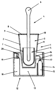
Fig. 1 shows a cleaning container 1 having a first container element 2 with a
main
chamber 3 in which a cleaning device 4 with a cleaning head 5 and a handle 6
is situated.
The cleaning device 4 in the embodiment depicted here is a toilet brush
without any
restriction on generality. The cleaning head 5 has bristles 7. The main
chamber 3 is closed
and sealed toward the outside by means of a cover element 8 arranged on the
handle 6 of
the cleaning device 1. An additional seal is achieved by the sealing ring 9
which rests on a
step-shaped shoulder 10 in the inside area of the wall I 1 of the container
element 2.
Reference number 12 in the figure denotes a second container element which has
a
secondary chamber 13. A spray bottle 15 containing a cleaning fluid is
arranged in a
hollow cylindrical holder 14 at the side of the secondary chamber 13. The main
chamber 3
and the secondary chamber 13 are connected to one another at the height of the
head 17 of
the spray bottle 15 through an opening 16. In addition, a supporting element
18 with a
spring element 19, the function of which will be discussed in greater detail
below, is also
situated in the secondary chamber 13.
It can be seen in the figure that the main chamber 3 and the secondary chamber
13
according to the invention are designed as separate container elements 2, 12.
In particular
the container element 2 is inserted into the container element 12 in the
embodiment shown
here. The container element 2 is supported here on the head 17 of the spray
bottle 15 and
on the supporting element 18 with the spring element 19. Several supporting
elements 18
distributed over the circumference of the container element 12 may expediently
be
provided with spring elements 19. For emptying, cleaning or changing the spray
bottle 15,
7
CA 02666827 2009-04-20
the container element 2 is easily lifted upward out of the container element
12. Following
the cleaning process and/or after replacing the spray bottle 15, the container
element 2
may again be inserted from above into the container element 12.
The container element 12 has a slightly larger cross-sectional area than the
container
element 2 bordering the main chamber 3 and therefore forms a type of base body
for the
container element 2 so that a greater stability is achieved.
The container element 2 has a shield 20 which extends horizontally outward on
its outside
circumference in the lower area, serving to rest on the supporting elements 18
with the
spring bodies 19 as well as on the head 17 of the spray bottle 15. In the area
of the head 17
of the spray bottle 15, the shield 20 has an axial extent, which serves as the
operating
element 21 for the spray bottle 15. By briefly exerting pressure on the handle
6 of the
cleaning device 4, the container element 2 is pressed briefly downward against
the spring
force of the spring body 19. By means of the operating element 21, the head 17
of the
spray bottle 15 is also pressed downward, with the result cleaning fluid comes
out for a
short period of time and passes through the opening 16 into the main chamber 3
with the
cleaning head 5. Due to the fact that the main chamber 3 is sealed with
respect to the
outside, as described above, the cleaning fluid acts on the cleaning head 5 of
the cleaning
device 4 in such a high concentration that a very good disinfection effect is
achieved after
only a short period of time.
Fig. 2 shows another preferred embodiment of the invention. The same parts are
provided
with the same reference numerals. In the embodiment shown in Fig. 2, the
secondary
chamber for the spray bottle 15 is formed by a centrally arranged hollowed
cylindrical
receptacle 22 in the container element 12. A radial expansion 23 to receive
the container
element 2 is connected to the hollow cylindrical receptacle 22 toward the top.
The opening
16 to the main chamber 3 of the container element 2 is situated directly above
the head 17
of the spray bottle 15 in the bottom of the container element 2 so that in
operation of the
opening mechanism for the spray bottle 15, the cleaning fluid is sprayed from
beneath into
the main chamber 3 with the cleaning head 5.
The hollow cylindrical receptacle 22 for the spray bottle 15 as well as the
radial expansion
23 for insertion of the container element 2 are bordered by an operating
element 24 which
8
CA 02666827 2009-04-20
can be inserted into a corresponding receptacle 26 in the container element 12
and can be
displaced vertically downward with respect to it against the force of a spring
element 27
arranged in the bottom of the container element 12. This arrangement allows
automatic
closing of the container 2 on insertion of the cleaning device 4, as will be
described below.
For closing and sealing in the embodiment presented here, two hemispherical
elements
28a, 28b are provided so that they are hinge-connected to the upper
circumferential area of
the container element 12 and can be pivoted toward one another. The two
hemispherical
elements are in an open position in the figure. For automatic pivoting into
the closed
position on insertion of the cleaning device 4 into the main chamber 3, lever
elements 29a,
29b which are fixedly connected to the hemispherical elements 28a, 28b are
provided,
these elements being hinge-connected to the container element 12 in the area
of the radial
expansion on the inside wall as well as on the operating element 24.
In exerting pressure from above onto the container element 2, e.g., in
adjusting the
cleaning device 4 into the main chamber 3, it is moved downward (the element
is moved
downward) and exerts a corresponding pressure on the operating element 24,
which is also
moved downward against the spring force of the spring element 27 in the same
way. Due
to this movement of the operating element 24, the lever elements 29a, 29b
which are
hinge-connected to the operating element 24, are tilted downward, which leads
to a
pivoting movement of the hemispherical elements 28a, 28b in the direction of
their closed
position. In the ideal case the spring force of the spring element 27 and the
weight of the
cleaning device 4 are coordinated with one another in such a way that the
insertion of the
cleaning device 4 leads only to closing of the container element 2 so that the
opening
mechanism of the spray bottle 15 is triggered only when further pressure is
exerted on the
handle 6 of the cleaning device 4. This has the advantage that the cleaning
device 4 can be
stored in the closed container element 2 without automatically resulting in
triggering of the
opening mechanism of the spray bottle 15.
In the embodiment shown here, the spray bottle 15 protrudes into the
receptacle for the
container element 2 in the area of the radial expansion 23 to such an extent
that by
additional brief depression after insertion of the cleaning device 4 into the
main chamber 3
and pivoting of the hemispherical elements 28a, 28b into their closed
position, the spray
9
CA 02666827 2009-04-20
head 17 is briefly depressed, with the result that cleaning fluid is briefly
sprayed upward
into the main chamber 3.
It can also be seen in the figure that the bottom 31 of the container element
12 is elevated
in the area of the opening 16 to prevent liquid from flowing out through the
opening 16.