Note: Descriptions are shown in the official language in which they were submitted.
CA 02666902 2014-12-03
22903-934
1 =
A rat trap
The invention relates to a rat trap comprising a plate with a first side and a
second side and with a number of through-going openings from the first to
the second side; a number of spikes secured to an anchoring plate, said
anchoring being arranged on the first side of said plate ..and wherein each
=
spike Is adapted to the Individual openings In the plate to the effect that a
spike can be caused to slide through such opening from the first side of the
= . plate to the second side of the plate; an. energy supply; a
release
mechanism; a sensor adapted for detecting the presence of a rat within' the
range of the spikes on the second side of the plate; a firing mechanism
= capable of ejecting one or more of such spikes through the openings when
the presence of a rat is detected by the sensor.
= 15 Rats in the sewage system are an ever increasing problem which
entails
= considerable problems of a technical as well as a sanitary nature. For
instance, rats may cause damage by perforating sewer pipes and building
nests in the soil surrounding the pipes. Thereby the pipes may settle and
become leaky, but they may also be clogged due to rats' nests literally
blocking or the pipes may even collapse when the surrounding soil yields due
to sometimes very large rats' nests. Thereby sewage water seeps out into
= the surroundings with ensuing increased risks of spread of diseases.
Besides, the rats themselves spread diseases and since they are able to
travel considerable distances they are, regrettably, a considerable source of
disease spreading. It is therefore desired ¨ not only from a health point of
.
view, but also from a financial point of view ¨ to exterminate rats in general
and including in the sewer system.
= It has therefore been attempted to use both mechanical and chemical means
to eliminate rats, but both methods are associated with deficiencies and
weaknesses. For instance, rats adjust very easily which Is also reflected in
= .
CA 02666902 2014-12-03
22903-934
=
=
2
their unique ability to develop resistance to the poisons used, and therefore
it
has continuously been necessary to develop and use Increasingly more
aggressive poisons that are poisonous not only to humane, but also to many
of our useful animals that are consequently unintentionally exposed to
serious risk of poisoning.
The purely mechanical solutions such as eg snares or drop traps have been
found to have weaknesses, rats being intelligent animals with high learning
abilities. Precisely those properties mean that the rats. are very conscious
about eg .a dead rat being a clear signal of danger and 'consequently they
avoid, to a large extent, areas where there have beeri or still are dead
animals in such mechanical traps. This pattern of behaviour. thus entails
problems in connection with the mechanical traps that consequently need
careful emptying and/or frequent moving since, as mentioned, the rats
quickly avoid the surroundings where such traps occur.
By the Invention it has surprisingly been found that it is possible, In an
easy
and efficient manner, to exterminate rats by means of a mechanicat trap
without said drawbacks, the rat trap being configured to further comprise a
withdrawal mechanism that will, after a given period of time, withdraw the
spikes through the openings In the plate, whereby the plate serves as stop
element and hence releases a rat spiked by one or more spikes.
By providing the rat trap with such withdrawal mechanism and moreover
positioning the trap where the released rat can be flushed away by the
= sewage water, the killed rat will quickly disappear from the surroundings
of
the trap and thereby it is accomplished not only that the trap is fully.
automated, but also that the dead rat Is no longer able to serve as warning
signal to the other rats that a danger lurks in the vicinity of a the trap.
=
CA 02666902 2014-05-07
. 22903-934
2a
According to one embodiment, there is provided a rat trap comprising a plate
with a
first side and a second side and with a number of through-going openings from
the
first to the second side; a number of spikes secured to an anchoring plate,
said
anchoring plate being arranged on the first side of said plate, and wherein
each spike
is adapted to the individual openings in the plate to the effect that a spike
is able to
slide through such opening from the first side of the plate to the second side
of the
plate; an energy supply coupled to a firing mechanism; a sensor adapted to
detect
the presence of a rat within the reach of the spikes on the second side of the
plate;
wherein the firing mechanism is powered by the energy supply for ejecting one
or
more of these spikes through the openings when the presence of a rat is
detected by
the sensor, and wherein the rat trap further comprises a withdrawal mechanism
which, following a given period of time, engages and withdraws the spikes
through
the openings in the plate, whereby the plate serves as stop means and hence
releases a rat spiked by one or more of the number of spikes, said plate with
the first
side and the second side and with the number of through-going openings from
the
first to the second side is constituted of a member shaped to engage a sewer
pipe.
CA 02666902 2014-12-03
st
22903-934
3
=
According to one embodiment the rat trap comprises electronic means for
recording and storing information regarding operational parameters such as
the number of firings or eg the battery state of the trap or its available
memory. By configuring the rat trap with an electronic memory It Is possible,
5 at any time, to obtain a clear Indication whether the trap is active and
hence may
kill many rats or whether the trap Is Inactive. In particular Information on
' inactivity may be a very useful Indication that something is wrong and that
consequently the mechanical state of the trap needs to be checked. It may
also be that the trap is quite simply to be moved as the Information Indicates
10 that rats do no appear in the vicinity of the trap.
According to one embodiment the spikes are withdrawn following a
.predetermlned period of time, which is the time it is assumed to take for the
rat to die.,
Acaording to one embodiment the trap comprises electronic means for
wireless transmission of operational parameters to a receiver unit eg at
ground level. By transferring operational parameters to ground level, the
need to inspect or collect the unit manually is obviated, and consequently the
20 need for sending crew Into the sewage system is limited.
According to a further embodiment the trap comprises electronic means for
transferring operational parameters to a network such as eg a mobile
telephone network. Thereby the rat trap can be monitored-from a distance or
25 remote-operated, via eg the Internet. By providing the trap with such
means
.
several traps can be monitored centrally, and therefore it Is possible not
only
to save crew, but it is also an option to provide improved numerical
processing of Information such as eg current information on the amount of
rats in given geographical zones. However, it is also an option to switch off
30 the trap prior to inspection or mounting. Thereby it is also possible to
avoid
accidents= in connection with unintentional firings during eg mounting or
=
CA 02666902 2009-04-17
WO 2008/046424 PCT/
K2007/000449
4
inspection. Also, it is possible to test the functionality of the trap by
remote-
firing it or even to completely switch off the trap if it malfunctions in one
way
or another.
The wireless communication as such via the mobile network can easily be
established by means of eg a small antenna at ground level which is
connected via a cable to the trap.
According to one embodiment the plate is constituted of a flexible tubular
member adapted such that it is able to resiliently engage with a sewage pipe
and, in a preferred embodiment, such resilient member is in the shape of a
semi-cylindrical shield. This configuration of the plate enables the
mechanical
part of the trap to be arranged on the surface of the shield. Thereby a
particularly advantageous embodiment is accomplished which is easily
mounted in the pipes in a sewer shaft as the flexible part is merely to be
inserted into resilient engagement with the inside of one of the pipes that
extend into or out of the shaft.
According to one embodiment the withdrawal mechanism is constituted of an
electromagnetic mechanism such as eg a solenoid or a coil. By configuring
the withdrawal mechanism around a solenoid, a very quick mechanism is
accomplished, meaning that the same mechanism can also be used to fire
the spikes, too.
According to one embodiment, the withdrawal mechanism is constituted of a
spindle mechanism adapted to withdraw the spikes. By configuring the
withdrawal mechanism around a spindle solution, it is an option to use a
motor with a relatively small moment of rotation and consequently it is also
an option to also use the spindle mechanism to compress the springs in a
firing mechanism.
=
CA 02666902 2009-04-17
WO 2008/046424 PCT/
K2007/000449
According to one embodiment the trap comprises a light sensor
communicating electronically with the firing mechanism to the effect that the
firing mechanism is interrupted when light occurs that is above a given
intensity. By providing the trap with means for switching off the firing
5 mechanism when a light intensity above a given level occurs, it is
possible to
prevent accidents due to eg erroneous activation of the trap in case of
ordinary localised work illumination, including eg also in daylight at ground
level or in artificial work illumination at the bottom of a shaft. Such light-
activated safety means may of course also be adapted to be such that they
switch off the trap merely if a superposed well cover is opened in daylight.
According to one embodiment the rat trap comprises electronic means for
transferring images to a network, eg a mobile telephone network. Thereby
the rat trap can be remote-monitored visually via eg the internet and
therefore it is also possible to perform a visual inspection of the technical
functionality of the trap eg by enabling the trap to be remote-fired.
According to one embodiment the trap is provided with light and/or a camera
for transferring images to a network such as eg a mobile telephone network
to the effect that the trap can be remote-monitored via eg the internet.
Thereby a further option of collecting information is provided.
Other embodiments are recited in the dependent claims.
List of figures.
Now the invention will be described in further detail with point of departure
in
the figures; wherein
Figure 1 schematically shows the construction of an embodiment of the rat
trap;
-
CA 02666902 2009-04-17
WO 2008/046424 PCT/ K2007/000449
= 6
Figure 2 schematically shows two depictions of an embodiment of the rat trap
with the spring mechanism more or less tightened;
Figure 3 schematically shows an embodiment of the rat trap;
Figure 4 shows an embodiment of the trap mounted in a sewer shaft;
Figure 5 shows a tool for mounting a rat trap in a sewer pipe.
Reference being initially made to Figure 1, an embodiment of the invention
will be explained in further detail. The rat trap 1 comprises an automatic
mechanism (not shown in Figure 1) which is capable of both firing the spikes
3 and pulling them back in order to thereby release a spiked rat. This
mechanism will be described in further detail in the following with reference
to
Figures 2 and 3.
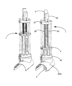
Figure 2 shows a rat trap 1. The rat trap comprises a plate 2 with a first
side
and a second side and having a number of through-going openings from the
first side to the second side. The rat trap is provided with a number of
spikes
3 that are secured to an anchoring plate 4. This anchoring plate is arranged
on the first side ¨ being in the depicted Figure the top face ¨ of the plate.
The
spikes 3 are adapted to the openings in this plate 2 to the effect that the
spikes are adapted not only to slide through the plate, rather spikes and
openings are also adapted such that the circumference of the spikes
corresponds essentially to the circumference of the openings.
The rat trap is automated in that the spikes 3 can both be fired and withdrawn
by means of interior automatics. An embodiment of. such automatics will be
explained in further detail with reference to Figures 2 and 3. To supply
energy to this firing and withdrawal mechanism, the rat trap is provided with
an energy supply 5, such as eg a power supply in the form of a battery as
CA 02666902 2009-04-17
WO 2008/046424 PCT/
K2007/000449
7
shown at the top of the drawing. However, the power may also come from
other sources, eg the mains system.
In order to detect the presence of an animal within the reach of the spikes,
the rat trap is usually provided with an electronic sensor (not shown). This
sensor may eg be an infrared sensor or other movement sensor, but of
course nothing prevents other sensors from being used. The sensor may
even rely entirely on mechanics.
If the sensor is based on infra-red measurement, one would usually arrange
the sensor to measure approximately centrally of the face area within which
the spikes hit. However, the sensor of the detector may also be based on
other measurement methods that are capable of detecting the presence of a
rat within a zone where the spikes are assumed to be able to kill the rat, be
it
eg by means of sound or movement, but, as mentioned, the sensor may also
rely on mechanics.
The trap may also comprise a light sensor (not shown) being in
communication with the firing mechanism such that the firing mechanism is
interrupted when light occurs that is above a given intensity. By providing
the
trap with means for switching off the firing mechanism when a light intensity
above a given level occurs, it is possible to prevent accidents due to eg
erroneous activation of the trap in case of ordinary localised work
illumination, including eg also in daylight at ground level or in artificial
work
illumination at the bottom of a shaft. Such light-activated safety means may
of course also be adapted to be such that they switch off the trap merely if a
superposed well cover is opened in daylight.
In the shown trap 1 the firing mechanism is founded on a spring mechanism
20 which is arranged between the anchoring plate 4 and a stop means 21. In
the shown mechanism the anchoring plate 4 is thus movable.
CA 02666902 2014-12-03
22903-934
= 8
=
Springs 20 are selected to have so much spring power that the spikes 3 are
moved at such speed and inertia through the openings in the plate that a rat
can be killed by the spikes when the firing mechanism is released.
The rat trap 1 is provided with a withdrawal mechanism which, after a given
period of time, withdraws the spikes 3 through the openings in the plate 2:- -
Thereby a (dead) rat spiked on the underside of the plate 2 is released, the
plate 2 thus serving as stop means.
The firing mechanism and withdrawal mechanism as such are, In the
example shown, based on la an electronic mechanism which Is able to
control and move the requisite mechanical parts of the trap and the
functioning as such will be explained in further detail In the following in
the
context of Figure 3.
Figure 3 schematically shows an embodiment of a firing and withdrawal
mechanism which will be explained in further detail in the following. When the
trap 1 is to be used, it is turned on by means of a not shown switch,
following
which a motor 30 starts to rotate an associated thread spindle 31 to the
effect
that a nut 32 mounted thereon starts to move upwards (in the Figure). Of
course, the nut is journalled in such a manner that it does not rotate with
the
spindle and, in the embodiment shown of the invention, this is accomplished
by means of two arms that prevent a rotation of the nut, while simultaneously
25' they allow an upwardly or downwardly oriented movement of the nut
from a
lower starting position (such as eg a position which is slightly lower than
the
position of the nut shown in Figure 1). Since the thread spindle is journalled
in an opening (a hole) in the anchoring plate 4 with sufficiently large fit
for the
anchoring plate 2 to slide effortlessly up and down the spindle without the
plate 2 corning into contact with the thread of the spindle, the rotation of
the
spindle does not in Itself influence the anchoring plate, but since,. however,
=
CA 02666902 2014-12-03
- 22903-934
9
the nut (32) is unable to travel through this opening to the thread spindle,
the
anchoring plate 4 Is pulled upwards when the nut hits It.
As the anchoring plate 4 moves upwards, the springs 20 are compressed
and the compression goes on until the anchoring plate 4 has assumed a
= predetermined position, where experience has shown that' the springs have
absorbed enough energy for them to thrust the=spikes out through the plate 2
with so much force that a rat within reach of the spikes can be killed.
In this position the anchoring plate is subsequently locked by a (not shown)
releasable locking mechanism and, in this position, the electronic control
unit
= of the trap also stops rotation of the spindle.
Now, the control unit starts. a counter-rotation of the spindle, which means
that only the nut is moved downwards, the anchoring plate still being locked.
The downwards movement of the nut continues unit the nut has again
essentially reached its lower starting position, following which the rotation
is
= discontinued. = -
=
Now, the trap is ready for firing and when that takes place (due to eg the
presence of a rat) the releasable locking mechanism releases the anchoring
plate 4 which Is then, at great speed, moved downwards until it hits a stop
being, in the example shown, In the form of a plate 33. .
=
= On their way, the spikes have, with great speed and much force, exited on
the other side of the plate 2 and are hence capable of killing a rat within
their
reach (on the underside of the plate 2). In order to be able to vary the
inertia
of this system and hence optimise the trap the plate is, according to a
particular embodiment, equipped to allow mounting and dismounting of
=
=
CA 02666902 2014-05-07
22903-934
weight elements. If the trap is situated in a sewer pipe, the dead rat will
eventually be flushed away by the water.
Albeit the trap is shown with a spring mechanism, the withdrawal mechanism
may, of
5 course, also be made in other ways. It may be constituted of eg an
electromagnetic
mechanism, (such as eg a solenoid or a coil 43 shown schematically in Figure
4). By
configuring the withdrawal mechanism around a solenoid it is possible to
accomplish
a very quick mechanism and this is why the same mechanism can also be used for
firing the spikes, too. It could also be a pneumatic or a hydraulic mechanism.
By
10 configuring the withdrawal mechanism around such air- and/or liquid-
based
mechanisms, it is also possible to accomplish very quick and reliable
mechanisms
that can also be used for firing the spikes, too.
Figure 4 shows a trap 1 which Is arranged at the bottom of a sewer shaft 50.
The trap 1 is mounted on a mounting member 40 which in the shown
embodiment is a flexible semi-cylindrical tubular member 40 that resiliently
engages a sewer pipe 41 but the mounting member could also be in form of
e.g, semi-cylindrical tubular member being provided with expanding means
such that it is capable of engaging the inner side of a pipe. The resilient=
member 40 may be made out of steel but other materials may be used such
as e.g. plastic.
In its unstressed state, the resilient tubular member 40 has an outer radius
which slightly exceeds the inner radius of the sewer pipe 41. Thereby the trap
is easily fastened therein merely by a trap fitter compressing the tubular
member 40 to such suitable extent that the tubular member 40 can be
Inserted into the sewer pipe 41. Then the fitter inserts the tubular member 40
into the sewer pipe 41 and lets go of it, following which the tubular member
40 resiliently engages the inside of the sewer pipe 41. Even though the
member 40 is describes as being made out of resilient material other
solutions known to the skilled person may be used, such as e.g.
CA 02666902 2014-05-07
22903-934
11
mechanically expanding sleeves. For illustrative purposes, the trap is shown
with the spikes out, but of course this is usually not the case unless the
trap
is to be serviced or the like.
Figure 5 shows a tool for mounting a trap in a sewer shaft and the
functionality of It will be explained In further detail in the following. The
tool
consists of two parts: a handle part 60 and =a stop plate 70. Moreover, the
figure also shows a resilient tubular member 40. As-explained above, the trap
. will usually be arranged on the tubular member (40), but for the
sake of
clarity this is not the case In the depiction shown in Figure 5.
The handle part is provided with a mounting pin 51, being in the shown
embodiment divided into three pieces 62, 63, 64, where only the middlemost
part 63 is provided wtth thread. The mounting pin is adapted to the stop plate
70 in such a manner that the thread mates with corresponding thread in the
stop plate, and the thread-less part of the mounting pin 64 which is situated
after the thread 63 is adapted to the thickness of the stop plate to the
effect
that the mounting pin 62, 63, 64 can be turned so far Into the stop plate 70
that the thread 63 on the mounting pin 61 does not engage with the thread of
the stop plate. Like the stop plate, the resilient tubular member 40 la
provided
with a thread mating with the thread on the mounting pin 60. That thread can
be constituted (as shown in the Figure) of a nut 65, but of course the thread
can be made in a variety of other ways.
=
When the tool is to be used, one starts out by mounting the stop plate 70 on
the mounting pin 61 and subsequenty timing it so far that the threads are no
longer in engagement. Then one may turn the thread 63 of the mounting pin
into the nut on the tubular element 40 and thereby the tubular member 40 is
pulled into the convex portion of the stop plate. During thls process the
tubular member 40 is deformed (compressed). The fitter continues this
deformation until the tubular member 40 can be pressed into the sewer pipe
CA 02666902 2009-04-17
WO 2008/046424 PCT/ K2007/000449
12
where the trap is to be mounted (not shown), following which the fitter
deploys the trap simply by turning the mounting pin out of engagement with
the tubular member 40.
Even though the stop plate 70 can be secured to the mounting pin in many
ways, eg by means of a known split pin system (arranged on the top face of
the thread portion 63 or a corresponding place) the embodiment as shown in
Figure 5 is associated with the advantage that several sizes of stop plates
(different diameters/curvatures) can be mounted on the same mounting pin
61. Thereby the fitter needs only one handle part which can then be used for
several different (different diameters/curvatures) stop plates which he
selects
in response to the size of tubular element 49 (fitted with trap) to be mounted
in a sewer.
Figure 6 shows a particular kind of spike, where the tips of the spikes are
configured with a central indentation 90. The indentation of the tips may
advantageously be configured like corresponding indentations in bullets for
weapons such as eg described in patent disclosures US6805057 B or
DE4435859 A1. However, as opposed to the technique taught in the above
referenced patents, the object served by such configuration of the spikes of
the rat trap is not that the tips are to deform but rather to maintain their
shape
when they pass through the rat. The indentation in the spikes thus serves to
remove as much tissue as possible and, thus, it has been found that spikes
configured with such indentations kill the rats far more quickly than spikes
that are merely pointed.
Albeit the trap was explained in a scenario where the trap is mounted in a
sewer pipe the trap may, of course, also be used elsewhere. Of course, it can
also be used to kill other animals than rats. The electronic sensor as such
is,
in the above examples, described as a single sensor, but the presence of an
animal may, of course, also be detected on the basis of several detections,
,
CA 02666902 2009-04-17
WO 2008/046424 PCT/ K2007/000449
13
such as eg detections of movement, light and/or heat. The hitting accuracy of
the trap can, of course, also be increased by making the firing depend on one
or more detection criteria being complied with prior to the trap being fired
(such as eg that both movement and heat must be detected).
Electronic/optical sensors for accurate detection of acceleration can also be
used for detecting signs of life within the radius of the spikes.
According to one embodiment the rat trap comprises electronic means for
transferring images or other parameters to a network, such as eg a mobile
telephone network. Thereby the rat trap can be remote-monitored visually via
eg the internet, and therefore it is also possible to perform a visual
inspection
of the surroundings of the trap or the technical functionality of the trap eg
by
enabling the trap to be remote-fired. Monitoring of the functionality of the
trap
can, of course, also be performed in other known ways, such as eg
electronically.
The trap being a self-emptying device and hence less maintenance-intensive
than other traps, the trap may advantageously also be equipped with means
for other monitoring tasks. For instance, the trap may be equipped with one
or more means for tasks such as monitoring and continuously recording the
water level, flow rate, flow, water quality/pollution, PH value or
temperature.
The trap may be provided with a data storage consisting of eg reference
values to the effect that it is able to perform a comparison of measured data
there with and, based on this, provide an alarm if a value for one or more of
the measured parameters falls outside the allowable reference values. The
alarm as such may take place eg by means of sound, light or radio signals,
eg through the mobile telephone net. If the trap is used for carrying out
monitoring tasks such as eg analyses of the water quality in the well, the
results can be stored electronically or be transferred by means of eg wireless
technology, but of course the results can also be transferred from the rat
trap
CA 02666902 2009-04-17
WO 2008/046424 PCT/ K2007/000449
14
to a receiver by means of other conventional technique such as eg wires,
fibre optics cables or the like.