Note: Descriptions are shown in the official language in which they were submitted.
CA 02667022 2009-04-20
WO 2008/046908
PCT/EP2007/061205
1
ELECTRIC EVAPORATOR DEVICE OF VOLATILE SUBSTANCES WITH
ADJUSTABLE EVAPORATION INTENSITY
DESCRIPTION
OBJECT OF THE INVENTION
The present invention relates to an electric
evaporator device of volatile substances with adjustable
evaporation intensity, of the type of those which are
connected to the electricity mains to emit a fragrance or
an insecticide by heating process, and in particular to
an evaporator for liquid formulations.
The invention can be usefully applied in the
field of electric evaporators for diffusing perfumes or
insecticides into the atmosphere, preferably in the home
range.
An object of the invention is to enable the
emanation flow of active substance emitted to be
continuously regulated between a minimum and a maximum
level, and avoid the escape of liquid outside the device
when an accidental increase of the power supply occurs,
thus protecting the device.
BACKGROUND OF THE INVENTION
Electric vaporizer devices of volatile
substances are known which evaporate perfumes or
insecticides into the surrounding atmosphere by adapting
to domestic electric power sockets, comprising a
container of the volatile substance, a resistive heating
element and means for activation by manual or automatic
operation with an operatively associated electronic
CA 02667022 2009-04-20
WO 2008/046908
PCT/EP2007/061205
2
circuit.
There is a particular type of devices having at
least a closed container of the active or volatile
substance, usually liquid substance, that comprises a
flat wall or membrane apt to be crossed through by the
emanated vapours, but not by the liquid, of the volatile
substance.
When the container is emptied or when the user
wants to change the liquid the container has to be
replaced with another new one.
In the field of electric home evaporators used
with liquid formulations, evaporators are already known
wherein the intensity of evaporation of the active
substance may be adjusted by modifying the relative
position of the heating means, which is normally an
electric resistance, with respect to that of the membrane
of the container containing the liquid solution of active
substance. Furthermore, evaporators are already known
wherein said intensity is manually adjusted by modifying
the area of an opening located between the container and
the surrounding atmosphere.
The main drawback of the above-described devices
is that the consumption rate of the volatile substance is
always the same, regardless of the position of the
regulation means. In the other hand said evaporation
adjustment system allows only two-position adjustment,
i.e. either a minimum flow or a maximum flow, and
therefore it is not possible to adjust with continuity
and precision the evaporation flow between a minimum
level and a maximum level. Finally, said devices have a
security problem in case of an accidental increase of the
power supply occurs, producing the breakage of the
CA 02667022 2009-04-20
WO 2008/046908
PCT/EP2007/061205
3
membrane, due to the excessive temperature of the heating
means, and thus the escape of the liquid contained in the
container.
DESCRIPTION OF THE INVENTION
The electric evaporator device of volatile
substances with adjustable evaporation intensity which
constitutes the object of this invention allows a
continuous regulation of the emanation intensity rate, by
the regulation of the consumption rate of the liquid
formulation, also with the objective to arrange a secure
device avoiding escapes of liquid due to any accidental
circumstances respecting the supply.
The object of the present invention is therefore
to provide an electric evaporator for volatile
substances, i.e. insecticides or fragancies, of the type
for use with liquid formulations, in which it is possible
to obtain an optimum and continuous adjustment in the
flow of evaporated active substance between a minimum
level and a maximum level, without the need for use of
complex mechanisms and also avoiding any displacement of
the electrical connections of the heating device during
the evaporator-flow adjustment operations.
The main aim of the present invention is to
realise a dispenser which enables an intensity of the
vapours dispensed into the air to be regulated, thus
increasing the temperature of resistance elements which
results in an increase in vaporization rate and therefore
in a greater vaporization of the fragrances into the
atmosphere.
There is also aim of the present invention to
CA 02667022 2009-04-20
WO 2008/046908
PCT/EP2007/061205
4
have a very low energy transfer towards the membrane, as
security means, in order to damp an excess of energy due
to an accidental increase of the power supply,
transformed in an excessive temperature in heating means
apt to transfer heat to said membrane, enabling the
evaporation of the volatile substance.
This object is achieved, according to the
present invention, by means of an electric evaporator for
volatile substances, preferably a liquid formulation of
an active substance, contained in a closed container
comprising a semi-permeable membrane, i.e. a flat wall,
for diffusing the volatile substance. The membrane is apt
to allow passing through emanating vapours of the
volatile substance but is not permeable to the liquid
contained in the container.
The container with the volatile substance
therein is apt to be permeated through the membrane,
being the volatilization of the substance low enough to
avoid evaporation at room temperature.
The electrical evaporator device proposed by the
invention comprises heating means, which comprises in
turn a heating plate, which defines two separated
chambers, i.e. a first chamber and a second chamber. In
addition the heating means comprises a heat generator,
for example an electrical resistance or the like,
supplied through a usual plug for connection to the
electric supply. The heat generator is apt to heat the
container and cause evaporation of the volatile
substance, being located inside the first chamber,
between the heating plate and the plug apt to connect the
heating means to main, for example comprising two contact
pins adapted to be inserted in a socket. The heating
plate is apt to transfer heat to the membrane of the
CA 02667022 2009-04-20
WO 2008/046908
PCT/EP2007/061205
container, located inside the second chamber adjacent to
the first chamber, and thus producing vapour emanation of
the volatile substance.
5
Inside the second chamber is housed the
container with the volatile substance to be evaporated,
whose membrane is heated by the heating means located in
the other continuous chamber, i.e. the first chamber.
The heat generator can be placed in any extreme
or intermediate position within the first chamber, also
designated as heating chamber, i.e. from close to the
heating plate to close to the plug.
The first chamber is defined by the heating
plate and a first cover, being the second chamber defined
by said heating plate and a second cover. The coupling to
each other of said first cover and second cover, joined
by means of mechanical engagement, constitutes an
external case of the device, apt to house and protect the
elements comprised by the evaporator device as well as
support and guide the connection plug which supplies
power to the heating means having likewise means of
engagement between the container and the external case.
According to the invention the first chamber,
also named heating chamber, wherein the heating means are
located, comprises intensity regulation means for
regulate the intensity of the vapours emanation by means
of regulation the consumption of the active substance.
The aforementioned intensity regulation means comprises
at least one regulation opening, or regulation window,
located in the first cover and whose area may be adjusted
by a shutter, apt to be hand controlled by the user,
enabling the exit of a heated air flow and apt to
regulate the temperature, i.e. heat quantity, in the
CA 02667022 2009-04-20
WO 2008/046908
PCT/EP2007/061205
6
heating plate and so in the first chamber, and thus
regulating the consumption rate of the volatile substance
what means to regulate the intensity of the vapours
emanation of said volatile substance. Thus the regulation
opening is apt to close and open, completely or partly,
the heating chamber and modify the heat and temperature
inside the heating chamber therein, enabling thus the
regulation of the evaporation rate.
The intensity regulation means comprises a
turnable pin linked to the shutter and apt to move it
along any intermediate position located between a maximum
position wherein the regulation opening is completely
closed and an off position wherein the regulation opening
is completely open.
When an user actuates the pin and places it in
the off position, the device does not work by means of a
contact between said pin and an internal switch apt to
interrupts the power supply to the heat generator, being
the regulation opening completely open. By the other
hand, when the pin is placed in the maximum position, the
device works, and the regulation opening is completely
closed so the heat flow to the surrounding atmosphere is
interrupted being maximum the heat quantity accumulated
in the first chamber, inhibiting its refrigeration, being
maximum the temperature in the heating plate and thus
being maximum the evaporation of the volatile substance.
Therefore, by means of the regulation of the
heat flow and the heat quantity accumulated in the first
chamber, by the situation of the pin that controls the
opening rate of the regulation opening, it is achieved
the regulation of the evaporation intensity. Obviously
when the pin is located in any intermediate position, the
evaporation intensity rate will be a direct proportion of
CA 02667022 2009-04-20
WO 2008/046908
PCT/EP2007/061205
7
the open area of the regulation opening.
Contrary to the regulation means comprised in
the state of the art, the intensity regulation means
proposed by the invention does not regulate the air flow
of the vapours emanated, by means of the regulation of an
opening located between a container of the volatile
substance and the surrounding atmosphere, what correspond
to the second chamber in the device of the invention.
However, the device according to the present invention
comprises intensity regulation means, for the regulation
of evaporation intensity of the volatile substance, apt
to regulate the heat flow in a closed first chamber, i.e.
heating chamber, formed by the heating plate and the
first cover of the external case, being said heating
plate apt to transmit the necessary heat quantity to the
membrane of the substance container, which is located in
an adjacent chamber, i.e. the second chamber.
By means of this device it is possible to have a
regulation of the heat flow in the closed heating
chamber, which produces a heat transfer regulation, i.e.
more or less heat transfer, from the heating plate to the
container of the volatile substance. When the heat flow
is interrupted in said first chamber, the heating plate
temperature increases till a maximum temperature, thus
producing a high evaporation rate of the active
substance.
The device can work both in manual or automatic
mode. The automatic operating mode works indefinitely if
the power supply is not interrupted. At any moment the
user can activate the manual operating mode or stop the
operation of the vaporizer device.
The container can be manufactured by known
CA 02667022 2014-02-19
27395-202
8
processes such as injection of plastic or thermoforming,
which provides mechanical consistency and allows printing
thereon of the information necessary for the user
concerning how it should be removed for use.
Obviously, the container, which is preferably
removable, comprises a closed body which contains the
volatile substance and releases vapours into the
surrounding atmosphere, which are emitted from the
volatile substance which is fluid, preferably liquid, but
can also be powder or semiliquid, or a paste or a gel.
Before use, an impermeable protection film,
removable at the moment of first use, is attached to the
semi-permeable wall, i.e. the membrane. The protection
film can be, for example, peelably coupled to the
membrane to prevent the volatile substance from exiting
before first use.
The vapour drawing flow, which in the above
described device is obtained using means for heating, can
be obtained in other ways, for example using means for
forced ventilation incorporated in the diffuser or
external thereof.
The electrical connector means can comprise a
contact pin adapted to be inserted in the cigarette
lighter socket of an automobile, or two contact leads
adapted to be connected to an electrical battery.
CA 02667022 2014-02-19
27395-202
8a
In accordance with this invention, there is provided
an electric evaporator device of volatile substances with
adjustable evaporation intensity, comprising: a container (1)
apt to contain volatile substances comprising a semi-permeable
membrane (2), heating means (3) comprising a heating plate (4),
which defines a first chamber (6) separated from a second
chamber (8), and a heat generator (5) located inside the first
chamber (6), intensity regulation means (12) comprising at
least a regulation opening (13), located in the first chamber
(6), wherein the area of said at least one regulation opening
(13) may be adjusted by a shutter (16), enabling the exit of a
heated air flow and apt to regulate the temperature both in the
first chamber (6) and the heating plate (4), enabling thus the
regulation of the evaporation rate.
DESCRIPTION OF THE DRAWINGS
Further characteristic features and advantages of the
present invention will better emerge, however, more clearly
from the following detailed description of a preferred but non-
exclusive embodiment of the invention,
CA 02667022 2009-04-20
WO 2008/046908
PCT/EP2007/061205
9
illustrated purely by way of nonlimiting example in the
accompanying figures of the drawings, in which:
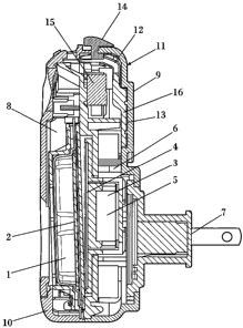
FIG. 1 - It shows a rear view of the electric
evaporator device proposed by the invention.
FIG. 2 - It shows a top view of the device,
wherein the turnable pin is in the off position.
FIG. 3 - It shows a side view of the device.
FIG. 4 - It shows a front view of the device.
FIG. 5 - It shows a view in perspective of the
device, wherein the regulation opening is in a complete
open position, being the turnable pin in the off position
as shown in figure 2.
FIG. 6 - It shows a rear view of the device,
wherein the regulation opening is in a complete closed
position, being the turnable pin in he maximum position,
contrary to shown in figure 5.
FIG. 7a and FIG. 7b - They show two exploded
perspective views of the elements constituent the device.
FIG. 8 - It show a side view in a cross-section
of the device, wherein the heating plate, the container
and the first and second chambers can be appreciated.
PREFERRED EMBODIMENT OF THE INVENTION
As it can clearly be seen in the various views
which are shown in the drawings, the evaporator according
the present invention comprises a closed container (1)
apt to contain volatile substances, preferably a liquid
CA 02667022 2009-04-20
WO 2008/046908
PCT/EP2007/061205
formulation of an active substance, comprising a semi-
permeable membrane (2) apt to allow passing through
emanating vapours of the volatile substance but not the
liquid contained in the container (1), being the
5
volatilization of the substance low enough to avoid
evaporation at room temperature.
Furthermore, it is pointed out that the
evaporator device comprises heating means (3), which
10
comprises in turn a heating plate (4), which defines a
first chamber (6) separated from a second chamber (8).
The heating means (3) comprises a heat generator (5),
consisting in an electrical resistance, supplied through
a plug (7) for connection to the electric supply. The
heat generator (5) is located inside the first chamber
(6), between the heating plate (4) and the plug (7). The
heating plate (4) is apt to transfer heat to the membrane
(2) of the container (1) located inside the second
chamber (8) adjacent to the first chamber (6).
Such as is observed in FIG. 8, the first chamber
(6) is defined by the heating plate (4) and a first cover
(9), being the second chamber (8) defined by said heating
plate (4) and a second cover (10). The first cover (9)
and second cover (10) are coupled to each other by means
of mechanical engagement, constituting an external case
(11) of the device.
According to the invention the first chamber
(6), with the heating means (3) therein, comprises
intensity regulation means (12), for regulate the
intensity of the vapours emanation, comprising a
regulation opening (13) located in the first cover (9)
and whose area may be adjusted by a shutter (16) linked
with a turnable pin (14) apt to be hand controlled by the
user, enabling the exit of a heated air flow and apt to
CA 02667022 2009-04-20
WO 2008/046908
PCT/EP2007/061205
11
regulate the temperature both in the first chamber (6)
and the heating plate (4), enabling thus the regulation
of the evaporation rate.
The pin (14) is apt move the shutter (16) along
any intermediate position located between a maximum
position wherein the regulation opening (13) is
completely closed, as shown in FIG. 6, and an off
position wherein the regulation opening (13) is
completely open, as shown in FIG. 5.
When the pin (14) is placed in the off position,
the device does not work by means of a contact between
said pin (14) and an internal switch (15) apt to
interrupts the power supply to the heat generator (5).
Contrary, when the pin (14) is placed in the maximum
position, the device works, and the regulation opening
(13) is completely closed so the heat flow to the
surrounding atmosphere is interrupted being maximum the
heat quantity accumulated in the first chamber (6), and
thus being maximum the evaporation of the volatile
substance.
The pin (14) can be located in any intermediate
position, being the evaporation intensity rate a direct
proportion of the open area of the regulation opening
(13).
The present invention has been described with
reference to a preferred embodiment, but it is clear that
the scope of protection of the invention is not limited
thereto but is extended to include the numerous
variations and modifications which are within the
competence of a person skilled in the art who is
acquainted with the present invention, provided that it
falls within the scope of the accompanying claims.