Note: Descriptions are shown in the official language in which they were submitted.
CA 02667695 2009-06-01
=
DEBRIS REMOVAL APPARATUS FOR A PUMP AND METHOD
Related Application
This non-provisional application claims priority from provisional application
no.
61/060,041, filed on June 9, 2008.
Field of the Invention
The present invention relates to pumping apparatuses and, more particularly,
to a
debris removal apparatus for a pump operating in certain conditions in which a
relatively
high concentration of solids is present, such as a pump operating to remove
heavy crude
oil.
Background of the Invention
Oil well and other fluid pumping systems are well known in the art. Such oil
well
pumping systems are used to mechanically remove oil or other fluid from
beneath the
earth's surface, particularly when the natural pressure in an oil well has
diminished.
Generally, an oil well pumping system begins with an above-ground pumping
unit, which
may commonly be referred to as a "pumpjack," "nodding donkey," "horsehead
pump,"
"beam pump," "sucker rod pump," and the like. The pumping unit creates a
reciprocating (up and down) pumping action that moves the oil (or other
substance being
pumped) out of the ground and into a flow line, from which the oil is then
taken to a
storage tank or other such structure.
1
CA 02667695 2009-06-01
Below the ground, a shaft is lined with piping known as "tubing." Into the
tubing
is inserted a string of sucker rods, which ultimately is indirectly coupled at
its north end
to the above-ground pumping unit. The string of sucker rods is ultimately
indirectly
coupled at its south end to a subsurface or "down-hole" pump that is located
at or near
the fluid in the oil well. The subsurface pump has a number of basic
components,
including a barrel and a plunger. The plunger operates within the barrel, and
the barrel,
in turn, is positioned within the tubing. It is common for the barrel to
include a standing
valve and the plunger to include a traveling valve. The standing valve has a
ball therein,
the purpose of which is to regulate the passage of oil from down-hole into the
pump,
allowing the pumped matter to be moved northward out of the system and into
the flow
line, while preventing the pumped matter from dropping back southward into the
hole.
Oil is permitted to pass through the standing valve and into the pump by the
movement of
the ball off its seat, and oil is prevented from dropping back into the hole
by the seating
of the ball. North of the standing valve, coupled to the sucker rods, is the
traveling valve.
The traveling valve regulates the passage of oil from within the pump
northward in the
direction of the flow line, while preventing the pumped oil from dropping back
southward, in the direction of the standing valve and hole.
Actual movement of the pumped substance through the system will now be
discussed. Oil is pumped from a hole through a series of downstrokes and
upstrokes of
the pump, which motion is imparted by the above-ground pumping unit. During
the
upstroke, formation pressure causes the ball in the standing valve to move
upward,
allowing the oil to pass through the standing valve and into the barrel of the
oil pump.
This oil will be held in place between the standing valve and the traveling
valve. In the
2
CA 02667695 2009-06-01
traveling valve, the ball is located in the seated position, held there by the
pressure from
the oil that has been previously pumped.
On the downstroke, the ball in the traveling valve unseats, permitting the oil
that
has passed through the standing valve to pass therethrough. Also during the
downstroke,
the ball in the standing valve seats, preventing pumped oil from moving back
down into
the hole. The process repeats itself again and again, with oil essentially
being moved in
stages from the hole, to above the standing valve and in the oil pump, to
above the
traveling valve and out of the oil pump. As the oil pump fills, the oil passes
through the
pump and into the tubing. As the tubing is filled, the oil passes into the
flow line, and is
then taken to the storage tank or other such structure.
There are a number of problems that are regularly encountered during fluid
pumping operations. Fluid that is pumped from the ground is generally impure,
and
includes solid impurities such as sand, pebbles, limestone, and other sediment
and debris.
Certain kinds of pumped fluids, such as heavy crude, tend to contain a
relatively large
amount of solids.
Solid impurities may be harmful to a pumping apparatus and its components for
a
number of reasons. For example, sand can become trapped between pump
components,
causing damage, reducing effectiveness, and sometimes requiring a halt to
pumping
operations and replacement of the damaged component(s). This can be both time
consuming and expensive.
One prior art solution has been the use of a progressive cavity pump, known as
a
PCP. However, a PCP utilizes an elastomeric stator, and is therefore unable to
maintain
quality in high temperature operation, as is generally required in the pumping
of heavy
3
CA 02667695 2012-10-02
73472-11
crude. Further, PCPs typically are not very tolerant of solids, and may have a
short
lifespan when pumping fluids containing abrasive solids. In addition, when
pumping
against high pressures, PCPs generally are required to be relatively lengthy,
and
accordingly, can be expensive.
The present invention addresses these problems encountered in prior art
pumping
systems and provides other, related, advantages.
Summary of the Invention
In accordance with an embodiment of the present invention, a debris removal
apparatus for a pumping system is disclosed. The debris removal apparatus
comprises, in
combination: a top drive gear assembly; a bottom drive gear assembly; a gear
pump
assembly interposed between the top drive gear assembly and the bottom drive
gear
assembly, an auger having one of a blade and a plurality of round plates,
wherein
the top gear assembly and the bottom gear assembly rotate the auger; a cyclone
housing positioned over a shaft of the auger and adapted to contain a cyclone
screen, wherein the cyclone housing is interposed between a portion of the
auger
and the bottom drive gear assembly; the cyclone screen positioned within the
cyclone housing; and an intake housing positioned over a portion of the auger,
wherein the intake housing includes at least one intake port.
In accordance with another embodiment of the present invention, a debris
removal
apparatus for a pumping system is disclosed. The debris removal apparatus
comprises, in
combination: a top drive gear assembly located at a northern end of the debris
removal
apparatus; a bottom drive gear assembly; a gear pump assembly interposed
between the
top drive gear assembly and the bottom drive gear assembly, wherein the gear
pump
4
CA 02667695 2012-10-02
73472-11
assembly comprises at least two gears, wherein the gears include teeth, the
teeth having
cavities adapted to trap debris therein; a plurality of coupler assemblies,
wherein a first
coupler assembly is interposed between a bottom of the top drive gear assembly
and a top
of the gear pump assembly, and a second coupler assembly is interposed between
a top of
the bottom drive gear assembly and a bottom of the gear pump assembly; an
auger; a
transmission housing positioned at a north end of the auger; an opening
positioned
proximate the transmission housing, wherein the opening is adapted to permit
gasses to
be ejected therethrough; a cyclone housing positioned over a shaft of the
auger and
adapted to contain a cyclone screen, wherein the cyclone housing is interposed
between a
blade of the auger and the bottom drive gear assembly; the cyclone screen
positioned
within the cyclone housing, wherein the cyclone includes a plurality of
openings adapted
to permit solids to be expelled therethrough; and an intake housing located at
a southern
end of the debris removing apparatus and positioned over the blade of the
auger, wherein
the intake housing includes a plurality of equidistantly spaced intake ports.
In accordance with a further embodiment of the present invention, a method for
pumping fluid is disclosed. The method comprises the steps of: providing a
debris
removal apparatus for a pumping system comprising, in combination: a top drive
gear
assembly; a bottom drive gear assembly; a gear pump assembly interposed
between the
top drive gear assembly and the bottom drive gear assembly; an auger; a
cyclone housing
positioned over a shaft of the auger and adapted to contain a cyclone screen,
wherein the
cyclone housing is interposed between a blade of the auger and the bottom
drive gear
assembly; the cyclone screen positioned within the cyclone housing; and an
intake housing
positioned over the blade of the auger, wherein the intake housing includes at
least one
5
CA 02667695 2009-06-01
intake port; utilizing the debris removal apparatus, pumping fluid; wherein
the fluid
enters the intake housing, then enters an interior portion of the cyclone
screen; causing
solids entrained in the fluid to exit the cyclone screen through openings in
the cyclone
screen, to then pass through a length of exhaust channels, to then exit the
debris removal
apparatus; wherein the fluid then passes through the bottom drive gear
assembly, then
enters the gear pump assembly; and wherein a portion of the fluid then enters
the top
drive gear assembly.
Brief Description of the Drawings
Figure 1 is a side, internal view of a debris removing apparatus consistent
with an
embodiment of the present invention.
Figure 2 is a side, cut-away view of the debris removing apparatus of Figure
1.
Figure 3 is a perspective view of a top drive gear assembly component of the
debris removing apparatus of Figures 1-2.
Figure 4 is a perspective, internal view of the top drive gear assembly of
Figure 3.
Figure 5 is a side, cross-sectional view of the top drive gear assembly of
Figure 3.
Figure 6 is a perspective view of an intake housing component of the debris
=
removing apparatus of Figures 1-2.
Figure 7 is a side view of the intake housing of Figure 6.
Figure 8 is a side, cut-away view of the intake housing of Figure 6.
Figure 9 is a bottom view of the intake housing of Figure 6.
Figure 10 is a top view of the intake housing of Figure 6.
F
6
CA 02667695 2009-06-01
Figure 11 is a perspective view of a pre-feed auger component of the debris
removing apparatus of Figures 1-2.
Figure 12 is a side view of the pre-feed auger of Figure 11.
Figure 13 is a top end view of the pre-feed auger of Figure 11.
Figure 14 is a perspective view of a cyclone housing component of the debris
removing apparatus of Figures 1-2.
Figure 15 is a side, cross-sectional view of the cyclone housing of Figure 14.
Figure 16 is a side view of the cyclone housing of Figure 14.
Figure 17 is an end view of the cyclone housing of Figure 14.
Figure 18 is a perspective view of a cyclone screen component of the debris
removing apparatus of Figures 1-2.
Figure 19 is a side view of the cyclone screen of Figure 18.
Figure 20 is an end view of the cyclone screen of Figure 18.
Figure 21 is a perspective view of a gear pump assembly component of the
debris
removing apparatus of Figures 1-2.
Figure 22 is a perspective, cut-away view of the gear pump assembly of Figure
21.
Figure 23 is a side, cross-sectional view of the gear pump assembly of Figure
21.
Figure 24 is a bottom end view of a pump gear component of the gear pump
assembly of Figure 21.
Figure 25 is a top end view of a pump gear component of the gear pump assembly
of Figure 21.
7
CA 02667695 2009-06-01
Detailed Description of the Preferred Embodiments
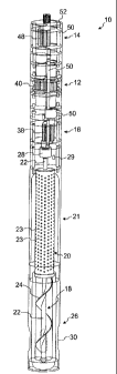
Referring first to Figures 1-2, a pump apparatus 10 ("pump 10") consistent
with
an embodiment of the present invention is shown. Beginning with the principal
components of the pump 10, a gear pump assembly 12 (as shown in more detail in
Figures 21-23) is interposed between a top drive gear assembly 14 (as shown in
more
detail in Figures 3-5) and a bottom drive gear assembly 16. (A coupler
assembly is
interposed between a bottom of the top drive gear assembly 14 and a top of the
gear
pump assembly 12, and a coupler assembly is also interposed between a top of
the bottom
drive gear assembly 16 and a bottom of the gear pump assembly 12.) The top
drive gear
=
assembly 14 may be located at a northern end of the pump 10. In one
embodiment, the
principal components of the pump 10 may be coupled together with bolts 50,
which may
be inserted in openings 52 provided in the gear pump assembly 12, top drive
gear
assembly 14, and bottom drive gear assembly 16. In this way, the principal
components
of the pump 10 may be properly aligned with one another. It may be desired to
employ
lag bolts, shoulder bolts, pins, or some other suitable device for purposes of
coupling
together the different components of the pump 10. It should be noted that, for
certain
embodiments, it may be desired to provide more than one gear pump assembly 12,
which
may be stacked. This may be desired in situations where, for example, there
may be a
need to transfer a greater amount of fluid over a given timeframe than one
gear pump
assembly 12 may be capable of transferring.
Preferably, the gear pump assembly 12, top drive assembly 14, and bottom drive
assembly 16 have outer dimensions appropriate for use with a given pipe into
which the
pump 10 may be inserted. For example, in one embodiment, the gear pump
assembly 12,
8
CA 02667695 2009-06-01
top drive assembly 14, and bottom drive assembly 16 may have outer dimensions
of
approximately 3 3/4 inches, such that they may be adapted for use with a 6-
inch pipe. This
helps to ensure that the annular space between the pipe and the pump 10 is
sufficient to
permit fluid to pass therethrough as it is being pumped. The gear pump
assembly 12, top
drive assembly 14, and bottom drive assembly 16 may have other outer
dimensions, such
as approximately 5 inches, approximately 6 inches, or some other desired
dimensions,
depending on the dimensions of the pipe with which the pump 10 is to be
employed.
Continuing with a summary of the principal components of the pump 10, the
drive
assemblies 14 and 16 rotate a pre-feed auger 18 (as shown in more detail in
Figures 11-
13). A cyclone screen 20 (as shown in more detail in Figures 18-20) located
within a
cyclone housing 21 (as shown in more detail in Figures 14-17) is positioned
over a shaft
22 of the pre-feed auger 18 and interposed between a blade 24 of the pre-feed
auger 18
and the bottom drive gear assembly 16. While in this embodiment the pre-feed
auger 18
with a radial-configured blade 24 is employed, it may be desired, for other
embodiments,
to incorporate round plates on the pre-feed auger 18, such as those that may
be found on
Tesla pumps or the like, as an alternative to radial-configured blade 24. Such
round
plates would use shear forces to move fluid. An intake housing 26 (as shown in
more
detail in Figures 6-10) is positioned over the blade 24 of the pre-feed auger
18, and
regulates fluid intake into the pump 10. The intake housing 26 may be located
at a
southern end of the pump 10. The entire pump 10 may be coupled, at a north end
thereof,
to a hydraulic pump, hydraulic motor, electric motor, or drive rod/shaft
powered at the
surface. When the pump 10 is coupled to a hydraulic motor, for example, it may
be
9
CA 02667695 2009-06-01
useful for cleaning power fluid that is used to drive a hydraulic motor in
coil tubing
operations and the like.
Turning more specifically to the top and bottom drive gear assemblies 14 and
16,
they cooperate to turn the pre-feed auger 18 at a desired rpm. In one
embodiment, the top
drive gear assembly 14 rotates at a first rpm, for example 450 rpm, and the
bottom drive
gear assembly 16 rotates at a lower rpm, for example 400 rpm. It may be
permitted, for
certain sizes of the pre-feed auger 18, to provide a top drive gear assembly
14 and a
bottom drive gear assembly 16 that are both rotating at the same rpm.
As noted above, the pre-feed auger 18 is rotated by the combined operation of
the
top and bottom drive gear assemblies 14 and 16. Rotational movement of the top
drive
gear assembly 14 is communicated to the bottom drive gear assembly 16 through
the gear
pump assembly 12, and the bottom drive gear assembly 16 is coupled to a
transmission
housing 28 (as shown in more detail in Figures 11-12) located on the pre-feed
auger 18.
Preferably, the transmission housing 28 is positioned at a north end of the
pre-feed auger
18. In one embodiment, it may be desired to include an opening 29 in the pump
10,
proximate the transmission housing 28, to permit gasses to be ejected
therethrough during
pumping operations, thereby preventing the pump 10 from becoming gas-locked.
It
should be noted that, for certain embodiments, it may be desired for the
opening 29 to be
omitted.
Referring now to the intake housing 26, as seen in Figures 1-2, it is
positioned at a
southern end of the pump 10, and houses the pre-feed auger 18. The intake of
fluid into
the pump 10 occurs through intake ports 30, located around the intake housing
26. In one
embodiment, there are four intake ports 30, located equidistantly around a
circumference
F
4
CA 02667695 2009-06-01
of the intake housing 26. It should be noted that, for certain embodiments, it
may be
desired to provide more than four or less than four intake ports 30.
A pumping of fluid through pump 10 will now be described. Fluid from a
formation enters intake ports 30. The pre-feed auger 18, which will be
spinning at a
faster rate than the turning of the individual top and bottom drive gear
assemblies 14 and
16, forces the fluid northward within the pump 10. This has the effect of
pressurizing the
fluid intake, pre-loading the pump 10. This prevents the pump 10 from
starvingicavitating during operation, since the pump 10 does not depend on
gravity to
move fluid therethrough. It also creates residence time for the pumped fluid
to move
from the pre-feed auger 18 to the intake for the gear pump assembly 12.
Because of the action of the pre-feed auger 18, the pumped fluid is spinning
as it
travels northward above the pre-feed auger 18 and into the interior of the
cyclone screen
20. As the fluid spins, solids in the fluid are moved toward the cyclone
screen 20, and
are permitted exit via openings 23 in the cyclone screen 20. Solids that have
exited the
cyclone screen 20 via openings 23 enter a space between the cyclone screen 20
and the
cyclone housing 21, and are permitted to drop into an upper portion of the
intake housing
26, where they will enter exhaust channels 32 (as shown in Figure 6) located
therein.
After passing through a length of exhaust channels 32, solids exit via exhaust
ports 34 (as
shown in Figure 9). The exhaust channels 32 and intake ports 30 are offset in
relation to
each other, so that the exhaust channels may extend continuously from a top
portion of
the intake housing 26 to a bottom portion thereof, where solids may exit via
exhaust ports
34. In one embodiment, four exhaust channels 32 and four exhaust ports 34 are
included.
However, it should be noted that, for certain embodiments, it may be desired
to vary the
11
CA 02667695 2009-06-01
number of exhaust channels 32 and exhaust ports 34, such that more than four
or less
than four exhaust channels 32 and exhaust ports 34 are included. Fluid that
travels
northward through the cyclone screen 20, after removal of solids through the
openings 23
in the cyclone screen 20, passes through ports 36 in the bottom drive gear
assembly 16,
bypassing the gears 38. The fluid then enters the gear pump assembly 12, and
passes
between and around the gears 40 (as shown in Figures 22-25). Referring now to
Figure
25, it can be seen that in one embodiment, cavities 42 are provided on
individual teeth 44
of gears 40 of the gear pump assembly 12. Solids present in the pumped fluid
as it passes
through the gear pump assembly 12 may be trapped in the cavities 42, reducing
the risk
of damage to the gears 40. In addition, pumped fluid that may be captured
between gears
40 and stator 46 (Figure 23) is forced out through discharge.
It should be noted that the gear pump assembly 12 pumps the fluid at a slower
rate
than the pre-feed auger 18. In one embodiment, the pre-feed auger 18 may pump
twice
as much fluid as the gear pump assembly 12. For example, the gear pump
assembly 12
may be configured to pump fluid at a rate of 50 gallons per minute while the
pre-feed
auger 18 may be configured to pump fluid at a rate of 100 gallons per minute.
The fluid
pumped by the pre-feed auger 18 will pass northward into the cyclone screen 20
as
described above. The pumped fluid that is beyond the capacity of the gear pump
assembly 12, with removed solids entrained therein, will travel back down the
pump via
the cyclone housing 21 and the exhaust channels 32, before exiting the pump 10
via
exhaust ports 34. As can be seen from this description, configuring the pre-
feed auger 18
to pump at a faster rate than the gear pump assembly 12 permits removal of
solids prior
to their entry into the gear pump assembly 12.
=
12
1
CA 02667695 2009-06-01
Continuing with the description of the pumping of fluid through the pump 10,
the
pumped fluid that is not beyond the capacity of the gear pump assembly 12 will
travel
northward toward the top drive gear assembly 14, passing through ports 54
therein,
bypassing gears 48. Thereafter, the pumped fluid will continue travelling
northward,
eventually reaching the tubing.
The pump 10 may be configured such that its overall length is substantially
smaller than typical prior art pumps, such as PCPs. For example, in one
embodiment, the
pump 10 may be configured to range from approximately three to six or more
feet in
length, or some other preferred length. This is in contrast to typical PCPs,
which may be
up to forty or more feet in length, for example. By virtue of the length of
the pump 10, it
may be adapted for placement in subsurface areas that have been drilled both
vertically
and laterally.
While the invention has been particularly shown and described with reference
to
preferred embodiments thereof, it will be understood by those skilled in the
art that the
foregoing and other changes in form and details may be made therein without
departing
from the spirit and scope of the invention. For example, while various
components of the
invention have been described with reference to various dimensions thereof, it
will be
recognized by those skilled in the art that substantial benefit could be
derived from
alternative configurations of the invention in which different dimensions are
employed,
including those that deviate from the preferred dimensions, even
substantially, in either
direction.
1
13