Language selection

Search

Patent 2667881 Summary

Third-party information liability

Some of the information on this Web page has been provided by external sources. The Government of Canada is not responsible for the accuracy, reliability or currency of the information supplied by external sources. Users wishing to rely upon this information should consult directly with the source of the information. Content provided by external sources is not subject to official languages, privacy and accessibility requirements.

Claims and Abstract availability

Any discrepancies in the text and image of the Claims and Abstract are due to differing posting times. Text of the Claims and Abstract are posted:

  • At the time the application is open to public inspection;
  • At the time of issue of the patent (grant).
(12) Patent Application: (11) CA 2667881
(54) English Title: DRIVE MEANS
(54) French Title: MOYENS D'ENTRAINEMENT
Status: Deemed Abandoned and Beyond the Period of Reinstatement - Pending Response to Notice of Disregarded Communication
Bibliographic Data
(51) International Patent Classification (IPC):
  • F04C 15/00 (2006.01)
  • E21B 43/12 (2006.01)
  • F04C 02/107 (2006.01)
(72) Inventors :
  • HEAD, PHILIP (United Kingdom)
(73) Owners :
  • ARTIFICIAL LIFT COMPANY LIMITED
(71) Applicants :
  • ARTIFICIAL LIFT COMPANY LIMITED (United Kingdom)
(74) Agent: GOWLING WLG (CANADA) LLP
(74) Associate agent:
(45) Issued:
(22) Filed Date: 2009-06-01
(41) Open to Public Inspection: 2009-12-02
Availability of licence: N/A
Dedicated to the Public: N/A
(25) Language of filing: English

Patent Cooperation Treaty (PCT): No

(30) Application Priority Data:
Application No. Country/Territory Date
GB0809966.5 (United Kingdom) 2008-06-02

Abstracts

English Abstract


A drive means for downhole use comprises an input shaft and an output shaft,
the input
shaft being coupled to a means of rotation, the input shaft and the output
shaft being
torsionally coupled, the output shaft being coupled to the rotor of the
progressive cavity
pump, the input shaft lies in a first axis and the output shaft lies in a
second axis, the
second axis being parallel to the first axis but spaced from it so that the
output shaft
rotates about its axis while describing a circular path.


Claims

Note: Claims are shown in the official language in which they were submitted.

Claims
1. A drive means for downhole use, comprising an input shaft and an output
shaft, the
input shaft being coupled to a means of rotation, the input shaft and the
output shaft being
torsionally coupled, the output shaft being coupled to the rotor of the
progressive cavity
pump, wherein the input shaft lies in a first axis and the output shaft lies
in a second axis,
the second axis being parallel to the first axis but spaced from it so that
the output shaft
rotates about its axis while describing a circular path.
2. A drive means according to claim 1, wherein the output shaft is connect to
a
progressive cavity pump.
3. A drive means according to any previous claim, wherein the input shaft and
output
shaft are coupled by an interface comprising;
a male gear wheel having n outwardly projecting engaging means on the outer
circumference and
a female ring gear having n+ 1 or n+2 inwardly projecting engaging means on
the
inner circumference.
4. A drive means according to either previous claim, wherein the output shaft
is
supported on an eccentric bearing in a housing.

Description

Note: Descriptions are shown in the official language in which they were submitted.


CA 02667881 2009-06-01
Drive Means
This invention relates to drive means, particularly drive means for
progressive cavity
pumps.
A progressive cavity pump usually comprises a helical rotor disposed in a
double helical
bore. Sealed cavities exist between the surfaces of the rotor and stator, and
as the rotor
turns, these sealed cavities progress along the length of the pump. Thus fluid
entering a
forming cavity at one end of the pump is transported the length of the pump
until the
cavity reaches the other end of the pump. The rotor rotates about a central
axis, however
no part of the rotor lies on this axis, rather each part of the rotor is
spaced from the central
axis it orbits. Since a drive means usually generates a rotating output that
is coincident
with the axis of rotation, a jointed or flexible shaft is used to connect the
drive output to
the rotor.
Jointed or flexible shafts may suffer from wear. An object of the present
invention is to
provide an alternative means of driving the rotor.
According to the invention there is provided a drive means for downhole use,
comprising
an input shaft and an output shaft, the input shaft being coupled to a means
of rotation,
the input shaft and the output shaft being torsionally coupled, the output
shaft being
coupled to the rotor of the progressive cavity pump, wherein the input shaft
lies in a first
axis and the output shaft lies in a second axis, the second axis being
parallel to the first
axis but spaced from it so that the output shaft rotates about its axis while
describing a
circular path.
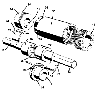
Figure 1 is an exploded perspective view of the drive means
Figure 2 is an exploded perspective view of the drive means viewed from
another angle
1

CA 02667881 2009-06-01
Figure 3 is an exploded perspective view of the drive means viewed from
another angle
Figure 4 is an exploded perspective view of the drive means viewed from
another angle
Referring to figures 1 and 2, the drive means comprises an input shaft 10
coupled to an
output shaft 12, disposed in a housing 30. The input shaft 10 protrudes
through the bore
of an input end cap 14 which is secured to the housing 30. Similarly, the
output shaft
12 protrudes through the bore 17 of an output end cap 16 which is secured to
the housing
10 30. A connector member 18 fits over the output end cap 16 and attaches to
the housing
30 with a thread. The input shaft 10 and output shaft 12 are supporting inside
the housing
30 by eccentric bearings 21, 23 respectively.
The input drive shaft 10 is coupled to some conventional drive means, that
rotates the
15 input drive shaft 10 about its central axis. The input drive shaft includes
a head 20
having a female outer rotor of a gerotor, ideally this is a three-lobed shape.
The input
drive head 20 is supported on an eccentric element 21. The output drive has a
corresponding output drive shaft head 22, which features a male inner rotor of
a gerotor,
ideally having a two-lobed shape, which engages with the female outer rotor of
the input
drive head 20. The output drive shaft head 22 is similarly supported on an
eccentric
bearing 22.
Referring to figure 4, the housing 30 has a bore 45 which accommodates the
input drive
shaft head 20 and output drive shaft head 22. The bore has a two lobed
section, in which
the crescent-shaped eccentric bearings 21, 22 sit, the bearings facing each
other when the
bore is considered axially. Each bearing 21, 22 has a ridge 31, 32 which
engages in slots
41, 42 on the inner surface of the bore 45 in order to locate them. The two-
lobed shape
of the bore 45 is offset from the central axis, so that the eccentric bearing
21 is radially
displaced further than the eccentric bearing 22. When the input drive shaft
head 20 is
2

CA 02667881 2009-06-01
resting in the bore 45 against the eccentric bearing 21, the input drive shaft
10 is
coincident with the centre axis of the housing 30. The output drive shaft head
22 is
disposed eccentrically, so that when it rests in the bore 45 against the
eccentric bearing
22, the output drive shaft 12 is spaced from the centre axis of the housing
30.
After the input and output drive shaft heads 20, 22 have been positioned in
the housing
30 with their respective eccentric bearings 21, 23, so that the male inner
rotor of the
output drive shaft head 22 engages with the female outer rotor of the input
drive shaft
head 20, the input and output drive shafts 10 and 12 are secured together by
input end cap
14 and output end cap 16 to the housing 30, with the input shaft 10 protruding
through
the central bore 15 of the input end cap 14, and the output shaft 12
protruding from the
eccentric bore 17 of the output end cap 16. The input end cap can be secured
for example
by pins placed in corresponding holes 34, 35 in the input end cap and the
housing. The
output end cap is rotationally constrained to the housing using pins 25 which
pass
through output end cap holes 24 and engage in corresponding holes 16 in the
housing.
Connector member 18 is then fitted over the output end cap.
In use, the input shaft 10 is rotated about its central axis. As the input
shaft head 20
rotates, the engagement of the female outer rotor causes the male inner rotor
of the output
shaft head 22, and therefore also the output shaft 12 itself, to also rotate.
However, the
male inner rotor is offset from the axis of rotation of the input shaft,
always engaging the
female outer rotor at a radially spaced position, the radial spacing being
constrained by
the eccentric bearing 23.
Although the radial spacing of the output shaft 12 is constrained by the
eccentric bearing,
the output shaft and housing are free to rotate relative to the outer housing
upon which it
is conveyed into the well and relative to the stator of a progressive cavity
pump
suspended beneath the drive means. The output shaft 12 is connected to the
rotor of a
progressive cavity pump. As previously described, the rotor of a progressive
cavity
3

CA 02667881 2009-06-01
pump is offset from the central axis of the stator. As the input shaft 10
rotates and causes
output shaft 12 to rotate, the output shaft and progressive cavity pump rotor
not only
rotate about their central axis, but also move around a circular path relative
to the stator
of the progressive cavity pump (whose axis coincides with the axis of the
input shaft).
As the input shaft is rotated, and so causes the output shaft and the
connected progressive
cavity pump rotor to rotate, the output shaft and the connected progressive
cavity pump
rotor also describe a circular path relative to the axis of the stator of the
progressive
cavity pump, the housing rotating to accommodate this movement.
Thus it will be seen that the progressive cavity pump rotor may be driven in
the required
manner without the use of a flexible or jointer member.
It will be noted that since the outer rotor of the input shaft 10 is a three-
lobed gerotor
shape and the inner rotor of the output shaft 12 is a two-lobed gerotor shape,
a single
revolution of the input shaft causes the output shaft to turn by approximately
1.5
revolutions (it will not be exactly 1.5 because of the circular movement of
the output
shaft itself). It will be realised that other gear ratios may be chosen, and
also that the
input shaft could feature a male shape and the output shaft could feature a
female shape.
Also, the bore of the housing could be shaped so that separate bearing
elements are not
required.
4

Representative Drawing
A single figure which represents the drawing illustrating the invention.
Administrative Status

2024-08-01:As part of the Next Generation Patents (NGP) transition, the Canadian Patents Database (CPD) now contains a more detailed Event History, which replicates the Event Log of our new back-office solution.

Please note that "Inactive:" events refers to events no longer in use in our new back-office solution.

For a clearer understanding of the status of the application/patent presented on this page, the site Disclaimer , as well as the definitions for Patent , Event History , Maintenance Fee  and Payment History  should be consulted.

Event History

Description Date
Application Not Reinstated by Deadline 2014-06-03
Time Limit for Reversal Expired 2014-06-03
Inactive: Abandon-RFE+Late fee unpaid-Correspondence sent 2014-06-02
Deemed Abandoned - Failure to Respond to Maintenance Fee Notice 2013-06-03
Application Published (Open to Public Inspection) 2009-12-02
Inactive: Cover page published 2009-12-01
Inactive: First IPC assigned 2009-10-06
Inactive: IPC assigned 2009-10-06
Inactive: IPC removed 2009-10-06
Inactive: IPC assigned 2009-10-06
Inactive: Declaration of entitlement - Formalities 2009-07-28
Reinstatement Requirements Deemed Compliant for All Abandonment Reasons 2009-06-30
Application Received - Regular National 2009-06-23
Inactive: Filing certificate - No RFE (English) 2009-06-23

Abandonment History

Abandonment Date Reason Reinstatement Date
2013-06-03

Maintenance Fee

The last payment was received on 2012-05-23

Note : If the full payment has not been received on or before the date indicated, a further fee may be required which may be one of the following

  • the reinstatement fee;
  • the late payment fee; or
  • additional fee to reverse deemed expiry.

Patent fees are adjusted on the 1st of January every year. The amounts above are the current amounts if received by December 31 of the current year.
Please refer to the CIPO Patent Fees web page to see all current fee amounts.

Fee History

Fee Type Anniversary Year Due Date Paid Date
Application fee - standard 2009-06-01
MF (application, 2nd anniv.) - standard 02 2011-06-01 2011-05-20
MF (application, 3rd anniv.) - standard 03 2012-06-01 2012-05-23
Owners on Record

Note: Records showing the ownership history in alphabetical order.

Current Owners on Record
ARTIFICIAL LIFT COMPANY LIMITED
Past Owners on Record
PHILIP HEAD
Past Owners that do not appear in the "Owners on Record" listing will appear in other documentation within the application.
Documents

To view selected files, please enter reCAPTCHA code :


To view images, click a link in the Document Description column. To download the documents, select one or more checkboxes in the first column and then click the "Download Selected in PDF format (Zip Archive)" or the "Download Selected as Single PDF" button.

List of published and non-published patent-specific documents on the CPD .

If you have any difficulty accessing content, you can call the Client Service Centre at 1-866-997-1936 or send them an e-mail at CIPO Client Service Centre.


Document
Description 
Date
(yyyy-mm-dd) 
Number of pages   Size of Image (KB) 
Abstract 2009-05-31 1 16
Description 2009-05-31 4 193
Drawings 2009-05-31 4 67
Claims 2009-05-31 1 30
Representative drawing 2009-11-05 1 14
Filing Certificate (English) 2009-06-22 1 157
Reminder of maintenance fee due 2011-02-01 1 112
Courtesy - Abandonment Letter (Maintenance Fee) 2013-07-28 1 172
Reminder - Request for Examination 2014-02-03 1 116
Courtesy - Abandonment Letter (Request for Examination) 2014-07-27 1 166
Correspondence 2009-06-22 1 17
Correspondence 2009-07-27 1 28