Sélection de la langue

Search

Sommaire du brevet 2667881 

Énoncé de désistement de responsabilité concernant l'information provenant de tiers

Une partie des informations de ce site Web a été fournie par des sources externes. Le gouvernement du Canada n'assume aucune responsabilité concernant la précision, l'actualité ou la fiabilité des informations fournies par les sources externes. Les utilisateurs qui désirent employer cette information devraient consulter directement la source des informations. Le contenu fourni par les sources externes n'est pas assujetti aux exigences sur les langues officielles, la protection des renseignements personnels et l'accessibilité.

Disponibilité de l'Abrégé et des Revendications

L'apparition de différences dans le texte et l'image des Revendications et de l'Abrégé dépend du moment auquel le document est publié. Les textes des Revendications et de l'Abrégé sont affichés :

  • lorsque la demande peut être examinée par le public;
  • lorsque le brevet est émis (délivrance).
(12) Demande de brevet: (11) CA 2667881
(54) Titre français: MOYENS D'ENTRAINEMENT
(54) Titre anglais: DRIVE MEANS
Statut: Réputée abandonnée et au-delà du délai pour le rétablissement - en attente de la réponse à l’avis de communication rejetée
Données bibliographiques
(51) Classification internationale des brevets (CIB):
  • F04C 15/00 (2006.01)
  • E21B 43/12 (2006.01)
  • F04C 02/107 (2006.01)
(72) Inventeurs :
  • HEAD, PHILIP (Royaume-Uni)
(73) Titulaires :
  • ARTIFICIAL LIFT COMPANY LIMITED
(71) Demandeurs :
  • ARTIFICIAL LIFT COMPANY LIMITED (Royaume-Uni)
(74) Agent: GOWLING WLG (CANADA) LLP
(74) Co-agent:
(45) Délivré:
(22) Date de dépôt: 2009-06-01
(41) Mise à la disponibilité du public: 2009-12-02
Licence disponible: S.O.
Cédé au domaine public: S.O.
(25) Langue des documents déposés: Anglais

Traité de coopération en matière de brevets (PCT): Non

(30) Données de priorité de la demande:
Numéro de la demande Pays / territoire Date
GB0809966.5 (Royaume-Uni) 2008-06-02

Abrégés

Abrégé anglais


A drive means for downhole use comprises an input shaft and an output shaft,
the input
shaft being coupled to a means of rotation, the input shaft and the output
shaft being
torsionally coupled, the output shaft being coupled to the rotor of the
progressive cavity
pump, the input shaft lies in a first axis and the output shaft lies in a
second axis, the
second axis being parallel to the first axis but spaced from it so that the
output shaft
rotates about its axis while describing a circular path.

Revendications

Note : Les revendications sont présentées dans la langue officielle dans laquelle elles ont été soumises.


Claims
1. A drive means for downhole use, comprising an input shaft and an output
shaft, the
input shaft being coupled to a means of rotation, the input shaft and the
output shaft being
torsionally coupled, the output shaft being coupled to the rotor of the
progressive cavity
pump, wherein the input shaft lies in a first axis and the output shaft lies
in a second axis,
the second axis being parallel to the first axis but spaced from it so that
the output shaft
rotates about its axis while describing a circular path.
2. A drive means according to claim 1, wherein the output shaft is connect to
a
progressive cavity pump.
3. A drive means according to any previous claim, wherein the input shaft and
output
shaft are coupled by an interface comprising;
a male gear wheel having n outwardly projecting engaging means on the outer
circumference and
a female ring gear having n+ 1 or n+2 inwardly projecting engaging means on
the
inner circumference.
4. A drive means according to either previous claim, wherein the output shaft
is
supported on an eccentric bearing in a housing.

Description

Note : Les descriptions sont présentées dans la langue officielle dans laquelle elles ont été soumises.

CA 02667881 2009-06-01
Drive Means
This invention relates to drive means, particularly drive means for
progressive cavity
pumps.
A progressive cavity pump usually comprises a helical rotor disposed in a
double helical
bore. Sealed cavities exist between the surfaces of the rotor and stator, and
as the rotor
turns, these sealed cavities progress along the length of the pump. Thus fluid
entering a
forming cavity at one end of the pump is transported the length of the pump
until the
cavity reaches the other end of the pump. The rotor rotates about a central
axis, however
no part of the rotor lies on this axis, rather each part of the rotor is
spaced from the central
axis it orbits. Since a drive means usually generates a rotating output that
is coincident
with the axis of rotation, a jointed or flexible shaft is used to connect the
drive output to
the rotor.
Jointed or flexible shafts may suffer from wear. An object of the present
invention is to
provide an alternative means of driving the rotor.
According to the invention there is provided a drive means for downhole use,
comprising
an input shaft and an output shaft, the input shaft being coupled to a means
of rotation,
the input shaft and the output shaft being torsionally coupled, the output
shaft being
coupled to the rotor of the progressive cavity pump, wherein the input shaft
lies in a first
axis and the output shaft lies in a second axis, the second axis being
parallel to the first
axis but spaced from it so that the output shaft rotates about its axis while
describing a
circular path.
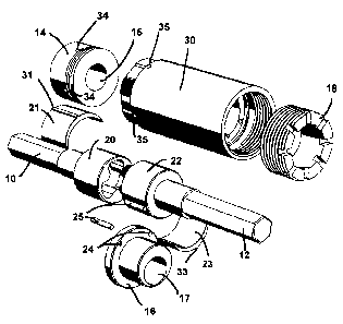
Figure 1 is an exploded perspective view of the drive means
Figure 2 is an exploded perspective view of the drive means viewed from
another angle
1

CA 02667881 2009-06-01
Figure 3 is an exploded perspective view of the drive means viewed from
another angle
Figure 4 is an exploded perspective view of the drive means viewed from
another angle
Referring to figures 1 and 2, the drive means comprises an input shaft 10
coupled to an
output shaft 12, disposed in a housing 30. The input shaft 10 protrudes
through the bore
of an input end cap 14 which is secured to the housing 30. Similarly, the
output shaft
12 protrudes through the bore 17 of an output end cap 16 which is secured to
the housing
10 30. A connector member 18 fits over the output end cap 16 and attaches to
the housing
30 with a thread. The input shaft 10 and output shaft 12 are supporting inside
the housing
30 by eccentric bearings 21, 23 respectively.
The input drive shaft 10 is coupled to some conventional drive means, that
rotates the
15 input drive shaft 10 about its central axis. The input drive shaft includes
a head 20
having a female outer rotor of a gerotor, ideally this is a three-lobed shape.
The input
drive head 20 is supported on an eccentric element 21. The output drive has a
corresponding output drive shaft head 22, which features a male inner rotor of
a gerotor,
ideally having a two-lobed shape, which engages with the female outer rotor of
the input
drive head 20. The output drive shaft head 22 is similarly supported on an
eccentric
bearing 22.
Referring to figure 4, the housing 30 has a bore 45 which accommodates the
input drive
shaft head 20 and output drive shaft head 22. The bore has a two lobed
section, in which
the crescent-shaped eccentric bearings 21, 22 sit, the bearings facing each
other when the
bore is considered axially. Each bearing 21, 22 has a ridge 31, 32 which
engages in slots
41, 42 on the inner surface of the bore 45 in order to locate them. The two-
lobed shape
of the bore 45 is offset from the central axis, so that the eccentric bearing
21 is radially
displaced further than the eccentric bearing 22. When the input drive shaft
head 20 is
2

CA 02667881 2009-06-01
resting in the bore 45 against the eccentric bearing 21, the input drive shaft
10 is
coincident with the centre axis of the housing 30. The output drive shaft head
22 is
disposed eccentrically, so that when it rests in the bore 45 against the
eccentric bearing
22, the output drive shaft 12 is spaced from the centre axis of the housing
30.
After the input and output drive shaft heads 20, 22 have been positioned in
the housing
30 with their respective eccentric bearings 21, 23, so that the male inner
rotor of the
output drive shaft head 22 engages with the female outer rotor of the input
drive shaft
head 20, the input and output drive shafts 10 and 12 are secured together by
input end cap
14 and output end cap 16 to the housing 30, with the input shaft 10 protruding
through
the central bore 15 of the input end cap 14, and the output shaft 12
protruding from the
eccentric bore 17 of the output end cap 16. The input end cap can be secured
for example
by pins placed in corresponding holes 34, 35 in the input end cap and the
housing. The
output end cap is rotationally constrained to the housing using pins 25 which
pass
through output end cap holes 24 and engage in corresponding holes 16 in the
housing.
Connector member 18 is then fitted over the output end cap.
In use, the input shaft 10 is rotated about its central axis. As the input
shaft head 20
rotates, the engagement of the female outer rotor causes the male inner rotor
of the output
shaft head 22, and therefore also the output shaft 12 itself, to also rotate.
However, the
male inner rotor is offset from the axis of rotation of the input shaft,
always engaging the
female outer rotor at a radially spaced position, the radial spacing being
constrained by
the eccentric bearing 23.
Although the radial spacing of the output shaft 12 is constrained by the
eccentric bearing,
the output shaft and housing are free to rotate relative to the outer housing
upon which it
is conveyed into the well and relative to the stator of a progressive cavity
pump
suspended beneath the drive means. The output shaft 12 is connected to the
rotor of a
progressive cavity pump. As previously described, the rotor of a progressive
cavity
3

CA 02667881 2009-06-01
pump is offset from the central axis of the stator. As the input shaft 10
rotates and causes
output shaft 12 to rotate, the output shaft and progressive cavity pump rotor
not only
rotate about their central axis, but also move around a circular path relative
to the stator
of the progressive cavity pump (whose axis coincides with the axis of the
input shaft).
As the input shaft is rotated, and so causes the output shaft and the
connected progressive
cavity pump rotor to rotate, the output shaft and the connected progressive
cavity pump
rotor also describe a circular path relative to the axis of the stator of the
progressive
cavity pump, the housing rotating to accommodate this movement.
Thus it will be seen that the progressive cavity pump rotor may be driven in
the required
manner without the use of a flexible or jointer member.
It will be noted that since the outer rotor of the input shaft 10 is a three-
lobed gerotor
shape and the inner rotor of the output shaft 12 is a two-lobed gerotor shape,
a single
revolution of the input shaft causes the output shaft to turn by approximately
1.5
revolutions (it will not be exactly 1.5 because of the circular movement of
the output
shaft itself). It will be realised that other gear ratios may be chosen, and
also that the
input shaft could feature a male shape and the output shaft could feature a
female shape.
Also, the bore of the housing could be shaped so that separate bearing
elements are not
required.
4

Dessin représentatif
Une figure unique qui représente un dessin illustrant l'invention.
États administratifs

2024-08-01 : Dans le cadre de la transition vers les Brevets de nouvelle génération (BNG), la base de données sur les brevets canadiens (BDBC) contient désormais un Historique d'événement plus détaillé, qui reproduit le Journal des événements de notre nouvelle solution interne.

Veuillez noter que les événements débutant par « Inactive : » se réfèrent à des événements qui ne sont plus utilisés dans notre nouvelle solution interne.

Pour une meilleure compréhension de l'état de la demande ou brevet qui figure sur cette page, la rubrique Mise en garde , et les descriptions de Brevet , Historique d'événement , Taxes périodiques et Historique des paiements devraient être consultées.

Historique d'événement

Description Date
Demande non rétablie avant l'échéance 2014-06-03
Le délai pour l'annulation est expiré 2014-06-03
Inactive : Abandon.-RE+surtaxe impayées-Corr envoyée 2014-06-02
Réputée abandonnée - omission de répondre à un avis sur les taxes pour le maintien en état 2013-06-03
Demande publiée (accessible au public) 2009-12-02
Inactive : Page couverture publiée 2009-12-01
Inactive : CIB en 1re position 2009-10-06
Inactive : CIB attribuée 2009-10-06
Inactive : CIB enlevée 2009-10-06
Inactive : CIB attribuée 2009-10-06
Inactive : Déclaration des droits - Formalités 2009-07-28
Exigences de rétablissement - réputé conforme pour tous les motifs d'abandon 2009-06-30
Demande reçue - nationale ordinaire 2009-06-23
Inactive : Certificat de dépôt - Sans RE (Anglais) 2009-06-23

Historique d'abandonnement

Date d'abandonnement Raison Date de rétablissement
2013-06-03

Taxes périodiques

Le dernier paiement a été reçu le 2012-05-23

Avis : Si le paiement en totalité n'a pas été reçu au plus tard à la date indiquée, une taxe supplémentaire peut être imposée, soit une des taxes suivantes :

  • taxe de rétablissement ;
  • taxe pour paiement en souffrance ; ou
  • taxe additionnelle pour le renversement d'une péremption réputée.

Les taxes sur les brevets sont ajustées au 1er janvier de chaque année. Les montants ci-dessus sont les montants actuels s'ils sont reçus au plus tard le 31 décembre de l'année en cours.
Veuillez vous référer à la page web des taxes sur les brevets de l'OPIC pour voir tous les montants actuels des taxes.

Historique des taxes

Type de taxes Anniversaire Échéance Date payée
Taxe pour le dépôt - générale 2009-06-01
TM (demande, 2e anniv.) - générale 02 2011-06-01 2011-05-20
TM (demande, 3e anniv.) - générale 03 2012-06-01 2012-05-23
Titulaires au dossier

Les titulaires actuels et antérieures au dossier sont affichés en ordre alphabétique.

Titulaires actuels au dossier
ARTIFICIAL LIFT COMPANY LIMITED
Titulaires antérieures au dossier
PHILIP HEAD
Les propriétaires antérieurs qui ne figurent pas dans la liste des « Propriétaires au dossier » apparaîtront dans d'autres documents au dossier.
Documents

Pour visionner les fichiers sélectionnés, entrer le code reCAPTCHA :


Pour visualiser une image, cliquer sur un lien dans la colonne description du document. Pour télécharger l'image (les images), cliquer l'une ou plusieurs cases à cocher dans la première colonne et ensuite cliquer sur le bouton "Télécharger sélection en format PDF (archive Zip)" ou le bouton "Télécharger sélection (en un fichier PDF fusionné)".

Liste des documents de brevet publiés et non publiés sur la BDBC .

Si vous avez des difficultés à accéder au contenu, veuillez communiquer avec le Centre de services à la clientèle au 1-866-997-1936, ou envoyer un courriel au Centre de service à la clientèle de l'OPIC.


Description du
Document 
Date
(aaaa-mm-jj) 
Nombre de pages   Taille de l'image (Ko) 
Abrégé 2009-05-31 1 16
Description 2009-05-31 4 193
Dessins 2009-05-31 4 67
Revendications 2009-05-31 1 30
Dessin représentatif 2009-11-05 1 14
Certificat de dépôt (anglais) 2009-06-22 1 157
Rappel de taxe de maintien due 2011-02-01 1 112
Courtoisie - Lettre d'abandon (taxe de maintien en état) 2013-07-28 1 172
Rappel - requête d'examen 2014-02-03 1 116
Courtoisie - Lettre d'abandon (requête d'examen) 2014-07-27 1 166
Correspondance 2009-06-22 1 17
Correspondance 2009-07-27 1 28