Note: Descriptions are shown in the official language in which they were submitted.
CA 02667987 2011-06-27
74420-326
1
Description
DIGITAL BROADCASTING SYSTEM AND METHOD OF
PROCESSING DATA
Technical Field
[1] The present invention relates to a digital telecommunications system, and
more par-
ticularly, to an apparatus and a method that are used for transmitting and
receiving
digital broadcast programs.
Background Art
[2] Presently, the technology for processing digital signals is being
developed at a vast
rate, and, as a larger number of the population uses the Internet, digital
electric
appliances, computers, and the Internet are being integrated. Therefore, in
order to
meet with the various requirements of the users, a system that can transmit
diverse sup-
plemental information in addition to video/audio data through a digital
television
channel needs to be developed.
[3] Some users may assume that supplemental data broadcasting would be applied
by
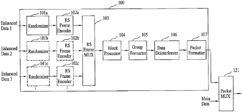
using a PC card or a portable device having a simple in-door antenna attached
thereto.
However, when used indoors, the intensity of the signals may decrease due to a
blockage caused by the walls or disturbance caused by approaching or proximate
mobile objects. Accordingly, the quality of the received digital signals may
be de-
teriorated due to a ghost effect and noise caused by reflected waves. However,
unlike
the general video/audio data, when transmitting the supplemental data, the
data that is
to be transmitted should have a low error ratio. More specifically, in case of
the video/
audio data, errors that are not perceived or acknowledged through the eyes or
ears of
the user can be ignored, since they do not cause any or much trouble.
Conversely, in
case of the supplemental data (e.g., program execution file, stock
information, etc.), an
error even in a single bit may cause a serious problem. Therefore, a system
highly
resistant to ghost effects and noise is required to be developed.
Disclosure of Invention
[4] The supplemental data are generally transmitted by a time-division method
through
the same channel as the video/audio data. However, with the advent of digital
broadcasting, digital television receiving systems that receive only
video/audio data are
already supplied to the market. Therefore, the supplemental data that are
transmitted
through the same channel as the video/audio data should not influence the
conventional
receiving systems that are provided in the market. In other words, this may be
defined
as the compatibility of broadcast system, and the supplemental data broadcast
system
CA 02667987 2011-06-27
74420-326
2
should be compatible with the broadcast system. Herein, the supplemental data
may
also be referred to as enhanced data. Furthermore, in a poor channel
environment,
the receiving performance of the conventional receiving system may be
deteriorated.
More specifically, resistance to changes in channels and noise is more highly
required when using portable and/or mobile receivers.
According to an aspect of the present invention, there is provided a
receiving system, comprising: a receiving unit for receiving a broadcast
signal, in
which M number of data groups, which include first error correction encoded
first
data, and second error correction encoded second data are multiplexed, wherein
a
size of the M number of data groups is a sum of K bytes (K_O) of dummy data
and
(N+2)*(187+P) bytes of a Reed-Solomon (RS) frame including the first data,
wherein
(N+2) is a number of bytes included in each row of the RS frame, wherein
(187+P) is
a number of bytes included in each column of the RS frame, wherein N is a
number
of bytes of the first data included in each row, and wherein P is a number of
bytes of
RS parity data included in each column; a demodulator for demodulating the
broadcast signal; a block decoder for decoding the first error correction
encoded first
data included in the demodulated broadcast signal in block units; and at least
one RS
frame decoder for performing error correction decoding on the block-decoded
first
data in RS frame units and correcting errors.
According to another aspect of the present invention, there is provided
a method of processing data in a receiving system, the method comprising:
receiving
a broadcast signal in which M number of data groups, which include first error
correction encoded first data, and second error correction encoded second data
are
multiplexed, wherein a size of the M number of data groups is a sum of K bytes
(K_O) of dummy data and (N+2)*(187+P) bytes of a Reed-Solomon (RS) frame
including the first data, wherein (N+2) is a number of bytes included in each
row of
the RS frame, wherein (187+P) is a number of bytes included in each column of
the
RS frame, wherein N is a number of bytes of the first data included in each
row, and
wherein P is a number of bytes of RS parity data included in each column;
demodulating the broadcast signal; decoding the first error correction encoded
first
CA 02667987 2011-06-27
74420-326
3
data included in the demodulated broadcast signal in block units; and
performing
error correction decoding on the block-decoded first data in RS frame units to
correct
errors.
[5] Some embodiments may provide a new digital broadcasting system
and a method of processing data that is suitable for transmitting supplemental
data
and that is highly resistant to noise.
[6] Some embodiments may also provide a digital broadcasting
transmitting/receiving system and a method of processing data that can perform
additional encoding on enhanced data and transmitting the processed enhanced
data, thereby enhancing the performance of the receiving system.
[7] According to another aspect a method of processing data of a
transmitting system includes the steps of receiving enhanced data through at
least a
plurality of paths, the enhanced data having information included therein,
grouping
enhanced data bytes being inserted by each path so as to create a RS frame,
performing error correction encoding in RS frame units, and performing
interleaving in
super frame units, each super frame being configured of a plurality of RS
frames,
receiving the interleaved RS frames through each path, thereby multiplexing
and
outputting the received RS frames in RS frame units, and performing encoding
on the
enhanced data at a coding rate of G/H, the enhanced data being multiplexed and
outputted, wherein G<H.
[8] As described above, some embodiments may have the following
advantages. More specifically, some embodiments may be highly protected
against
(or resistant to) any error that may occur when transmitting supplemental data
through a channel. Some embodiments may also be highly compatible to the
conventional receiving system. Moreover, some embodiments may also receive the
supplemental data without any error even in channels having severe ghost
effect and
noise.
CA 02667987 2011-06-27
74420-326
3a
Additionally, in some embodiments, by performing an error correction
encoding process and by performing interleaving in super frame units and
transmitting the processed data, robustness is provided to the enhanced data,
thereby enabling the enhanced data to respond adequately and strongly against
the
fast and frequent change in channels. Most particularly, by creating a
reliability map
when performing error correction decoding on the received data, and by
performing
the error correction decoding process while referring to the reliability
information of
the reliability map, the error correction performance on the received enhanced
data
may be enhanced. Furthermore, some embodiments may be even more effective
when applied to mobile and portable receivers, which are also liable to a
frequent
change in channel and which require protection (or resistance) against intense
noise.
Brief Description of the Drawings
[10] FIG. 1 illustrates a pre-processor within a transmitting system
according to an embodiment of the present invention;
[11] FIG. 2 illustrates a pre-processor within a transmitting system
according to another embodiment of the present invention;
[12] FIG. 3 illustrates a block diagram of a transmitting system
according to an embodiment of the present invention;
[13] FIG. 4(a) to FIG. 4(e) illustrate examples showing the steps of an
error correction coding process and an error detection coding process
according to
an embodiment of the present invention;
[14] FIG. 5(a) to FIG. 5(d) illustrate examples showing the steps of an
error correction coding process according to another embodiment of the present
invention;
[15] FIG. 6(a) to FIG. 6(d) illustrates an interleaving process in super
frame units according to an embodiment of the present invention;
CA 02667987 2011-06-27
74420-326
3b
[16] FIG. 7 and FIG. 8 respectively illustrate a data configuration before
and after a data deinterleaver with the transmitting system according to an
embodiment of the present invention;
[17] FIG. 9(a) and FIG. 9(b) each illustrates an exemplary process of
dividing a RS frame in order to configure a data group according to an
embodiment of
the present invention;
[18] FIG. 10 illustrates exemplary operations of a packet multiplexer for
transmitting a data group according to an embodiment of the present invention;
[19] FIG. 11 illustrates a demodulating unit within a receiving system
according to an embodiment of the present invention;
[20] FIG. 12 and FIG. 13 respectively illustrate different examples of an
enhanced data processing unit according to embodiments of the present
invention;
[21] FIG. 14 to FIG. 16 respectively illustrate different examples of a
decoding process of a RS frame decoder according to embodiments of the present
invention;
[22] FIG. 17 illustrates a block diagram showing a structure of a
receiving system according to an embodiment of the present invention; and
[23] FIG. 18 illustrates a block diagram showing a structure of a
receiving system according to another embodiment of the present invention.
Best Mode for Carrying Out the Invention
CA 02667987 2009-04-29
WO 2008/054044 PCT/KR2007/000164
4
[24] Reference will now be made in detail to the preferred embodiments of the
present
invention, examples of which are illustrated in the accompanying drawings.
Wherever
possible, the same reference numbers will be used throughout the drawings to
refer to
the same or like parts. In addition, although the terms used in the present
invention are
selected from generally known and used terms, some of the terms mentioned in
the de-
scription of the present invention have been selected by the applicant at his
or her
discretion, the detailed meanings of which are described in relevant parts of
the de-
scription herein. Furthermore, it is required that the present invention is
understood,
not simply by the actual terms used but by the meaning of each term lying
within.
[25] In the present invention, the enhanced data may either consist of data
including in-
formation such as program execution files, stock information, weather
forecast, and so
on, or consist of video/audio data. Additionally, the known data refer to data
already
known based upon a pre-determined agreement between the transmitting system
and
the receiving system. Furthermore, the main data consist of data that can be
received
from the conventional receiving system, wherein the main data include
video/audio
data. By performing additional encoding on the enhanced data and by
transmitting the
processed data, the present invention may provide robustness to the enhanced
data,
thereby enabling the data to respond more effectively to the channel
environment that
undergoes frequent changes.
[26] Particularly, in the present invention, the transmitting system receives
a plurality of
enhanced data sets having other service information included therein. Thus,
the
transmitting system independently performs additional encoding processes and
transmits the additionally processed data. A receiving system receives the
processed
data being transmitted, so as to decode the processed data.
[27] FIG. 1 and FIG. 2 illustrate examples of a portion of the transmitting
system for
transmitting various types of enhanced data and independently performing
additional
encoding processes according to the present invention. Referring to FIG. 1,
the
transmitting system includes a pre-processor 100 and a packet multiplexer 121.
The
pre-processor 100 includes the same number of randomizers and RS frame
encoders.
Herein, the number corresponds to the type (or number of sets) of enhanced
data,
which are to be processed with additional encoding. The alignment order of the
randomizers ad RS frame encoders may vary in accordance with the design of the
system designer. For example, an RS frame encoder may be positioned behind a
randomizer. Alternatively, a randomizer may be positioned behind a RS frame
encoder.
[28] An example of a RS frame encoder being positioned behind a randomizer
will now
be described in detail as an embodiment of the present invention. In this
example, each
enhanced data set that is to be independently encoded is inputted to its
respective
CA 02667987 2009-04-29
WO 2008/054044 PCT/KR2007/000164
randomizer through different paths. Herein, each enhanced data set that is
being
inputted to each randomizer through a different path may correspond to
enhanced data
each having different types of services included therein. Alternatively, each
enhanced
data set may also correspond to enhanced data having the same service type
included
therein. However, in this case, each enhanced data set is independently
randomized by
the randomizer and is then encoded in RS frame units. For example, the
transmitting
system according to the present invention may receive an enhanced data set
including
stock information and an enhanced data set including weather information
through
different paths. Then, the received enhanced data sets are sequentially
processed in-
dependent randomizing and RS encoding processes. Furthermore, internal
parameters
of the RS frame encoders respectively performing RS frame encoding on each
enhanced data set being randomized by each randomizer may vary depending upon
priority levels or levels of importance of the enhanced data sets that are
being inputted.
[29] In the example of the present invention, first to third enhanced data
sets enhanced
data 1 to enhanced data 3 are inputted to first to third enhanced data
randomizers lOla
to 101c through each respective path.
[30] Furthermore, first to third RS encoders 102a to 102c are respectively
positioned at
the output end of the first to third enhanced data randomizer 101a to 101c. A
RS frame
multiplexer 103 is mutually provided at the output ends of the first to third
RS frame
encoders 102a to 102c. Herein, the RS frame multiplexer 103 multiplexes the
enhanced
data RS encoded by the first to third RS frame encoders 102a to 102c in RS
frame
units and outputs the multiplexed data. Then, a block processor 104, a group
formatter
105, a data deinterleaver 106, and a packet formatter 107 are sequentially
provided
after the RS frame multiplexer 103.
[31] In the present invention having the structure as shown in FIG. 1, the
first to third
enhanced data sets are respectively inputted to the first to third enhanced
data
randomizers lOla to 101c through different paths and then randomized,
respectively.
More specifically, by having each enhanced data randomizer lOla to 101c of the
pre-
processor 100 randomize the enhanced data, the randomizing process that is to
be
performed on the enhanced data by the randomizer positioned behind the packet
multiplexer 121 may be omitted. The enhanced data sets respectively randomized
by
the first to third enhanced data randomizers lOla to 101c are, then, inputted
to the first
to third RS frame encoders 102a to 102c, respectively. Each of the first to
third RS
frame encoders 102a to 102c groups a plurality of randomized enhanced data
bytes that
are being inputted, thereby creating a RS frame, respectively.
[32] Then, each RS frame encoder performs an error correction encoding in RS
frame
units. At this point, an error detection encoding process may or may not be
performed.
Thus, by providing robustness to the enhanced data, the corresponding data may
CA 02667987 2009-04-29
WO 2008/054044 PCT/KR2007/000164
6
respond to the severely vulnerable and frequently changing frequency
environment.
[33] Each of the first to third RS frame encoders 102a to 102c may group a
plurality of
RS frames to create a super frame so as to perform interleaving or permutation
in super
frame units. Thus, by providing robustness to the enhanced data, a group error
that
may occur due to a change in the frequency environment may be scattered,
thereby
enabling the corresponding data to respond to the severely vulnerable and
frequently
changing frequency environment. Hereinafter, the process of creating a RS
frame and
the process of performing error correction encoding in RS frame units by each
RS
frame encoder will now be described in detail with reference to FIG. 4 and
FIG. 5.
More specifically, FIG. 4 illustrates an example of performing error detection
encoding
after performing error correction encoding, thereby adding a checksum. And,
FIG. 5 il-
lustrates an example of omitting the error detection encoding process.
[34] In the present invention, RS encoding is applied as the error correction
encoding
process, and cyclic redundancy check (CRC) encoding is applied as the error
detection
encoding process. When performing RS encoding, parity data that are to be used
for
error correction are generated. And, when performing CRC encoding, CRC data
that
are to be used for error detection are generated. Other error detection
encoding
methods may be used instead of CRC encoding for error detection encoding
process.
Also, an error correction encoding method may be used to enhance the overall
error
correction performance in the receiving system.
[35] Referring to FIG. 4 and FIG. 5, the operations of one of the plurality of
RS frame
encoders (e.g., the first RS frame encoder 102a) will be described in detail.
In case of
the other RS frame encoders (e.g., the second and third RS frame encoders 102b
and
102c), the internal parameters may vary. However, since the basic operations
are
identical to that of the first RS frame encoder 102a, detailed description of
the same
will be omitted for simplicity.
[36] FIG. 4(a) to FIG. 4(e) illustrate examples showing the steps of an
encoding process
performed by the RS frame encoder according to an embodiment of the present
invention. More specifically, the RS frame encoder 102a first divides the
inputted
enhanced data bytes into units of an equal length A. Herein, the value A will
be
decided by the system designer. Accordingly, in the example of the present
invention
given herein, the specific length is equal to 187 bytes. Herein, the 187-byte
unit will be
referred to as a "packet" for simplicity. For example, if the enhanced data
being
inputted as shown in FIG. 4(a) correspond to a MPEG transport stream (TS)
packet
configured of 188-byte units, the first MPEG synchronization byte is removed,
as
shown in FIG. 4(b), thereby configuring a packet with 187 bytes.
[37] Herein, the MPEG synchronization bytes are removed because each of the
enhanced data packets has the same value. Furthermore, the process of removing
the
CA 02667987 2009-04-29
WO 2008/054044 PCT/KR2007/000164
7
MPEG synchronization bytes may be performed while the enhanced data randomizer
101 a randomizes the enhanced data. Herein, the RS frame encoder 102a may omit
the
process of removing the MPEG synchronization bytes. And, in this case, when
the
receiving system (or receiver) adds the MPEG synchronization bytes to the
data, the
derandomizer performs the process instead of the RS frame decoder. Therefore,
if a
fixed byte that can be removed is not included in the inputted enhanced data,
or if the
length of the inputted packet is not equal to 187 bytes, the enhanced data
that are being
inputted are divided into 187-byte units, thereby configuring a packet of 187
bytes.
[38] Subsequently, N number of packets configured of 187 bytes is grouped to
form a
RS frame, as shown in FIG. 4(c). At this point, an RS frame may be configured
by
serially inserting a 187-byte packet into a RS frame having the size of
N(rows)* 187(columns). Herein, each column of N number of RS frames includes
187
bytes, as shown in FIG. 4(c). Therefore, in the present invention, a
((187+P),187)-RS
encoding process is performed on each column, so as to generate P number of
data
bytes. Then, the generated P number of data bytes are added to the
corresponding
column behind the last data byte of the column, thereby creating a column of
(187+P)
bytes. Also, when the ((187+P),187)-RS encoding process is performed, as shown
in
FIG. 4(d), on all N number of columns, shown in FIG. 4(c), a RS frame having
the size
of N(rows)*(187+P)(columns) number of bytes may be created.
[39] As shown in FIG. 4(c) or FIG. 4(d), each row of the RS frame is
configured of N
number of data bytes. However, depending upon channel conditions between the
transmitting system and the receiving system, error may be included in the RS
frame.
When errors occur as described above, a checksum may be added to each row unit
in
order to verify whether error exists in each row unit. Herein, for example,
CRC data
(or CRC code or CRC checksum) may be used as the checksum. The RS frame
encoder 102a performs CRC encoding on the enhanced data being RS encoded so as
to
create (or generate) the checksum (e.g., the CRC checksum). The CRC checksum
that
is generated by CRC encoding process may be used to indicate whether the
enhanced
data have been damaged while being transmitted through the channel.
[40] As described above, the present invention may also use different error
detection
encoding methods other than the CRC encoding method. Alternatively, the
present
invention may use the error correction encoding method to enhance the overall
error
correction ability of the receiving system. FIG. 4(e) illustrates an example
of using a
2-byte (i.e., 16-bit) CRC checksum as the CRC data. Herein, a 2-byte CRC
checksum
is generated for N number of bytes of each row, thereby adding the 2-byte CRC
checksum at the end of the N number of bytes. Thus, each row is expanded to
(N+2)
number of bytes. Equation 1 below corresponds to an exemplary equation for
generating a 2-byte CRC checksum for each row being configured of N number of
CA 02667987 2009-04-29
WO 2008/054044 PCT/KR2007/000164
8
bytes.
[41] Equation 1
[42]
X=X16+X12+X6+1
[43]
[44] The process of adding a 2-byte checksum in each row is only exemplary.
Therefore,
the present invention is not limited only to the example proposed in the
description set
forth herein. As described above, when the process of RS encoding and CRC
encoding
are completed, the (187*N)-byte RS frame is expanded to a (N+2)* (I 87+P)-byte
RS
frame.
[45] Meanwhile, FIG. 5 illustrates another example of a RS frame encoding
process of
the RS frame encoder 102a, wherein the error detection encoding process is
omitted. In
the example shown in FIG. 5, the process of creating one packet by grouping A
number of enhanced data bytes (e.g., 187 enhanced data bytes) is identical to
the
process described in FIG. 4. More specifically, when the enhanced data being
inputted
correspond to a MPEG transport stream (TS) configured in 188-byte units, as
shown in
FIG. 5(a), a first MPEG synchronization data byte is removed (or deleted) in
order to
configure a packet formed of 187 data bytes, as shown in FIG. 5(b).
[46] However, since the error detection encoding process is not performed in
the
example shown in FIG. 5, (N+2) number of packets, each configured of 187 data
bytes, as shown in FIG. 5(c), is grouped so as to form one RS frame. At this
point, an
RS frame may be configured by serially inserting a 187-byte packet into a RS
frame
having the size of (N+2)(rows)*187(columns). Herein, each column of (N+2)
number
of RS frames includes 187 bytes, as shown in FIG. 5(c). Therefore, in the
present
invention, a ((187+P),187)-RS encoding process is performed on each column, so
as to
generate P number of data bytes. Then, the generated P number of data bytes
are added
to the corresponding column behind the last data byte of the column, thereby
creating a
column of (187+P) bytes. Also, when the ((187+P),187)-RS encoding process is
performed, as shown in FIG. 5(d), on all (N+2) number of columns, shown in
FIG.
5(c), a RS frame having the size of (N+2)(rows)*(187+P)(columns) number of
bytes
may be created.
[47] More specifically, the size of the RS frame being processed with error
correction
encoding and error detection encoding, as shown in FIG. 4, is the same as the
size of
the RS frame being process with error correction encoding, as shown in FIG. 5.
Herein,
the value of P may have the same value for each RS frame encoder 102a to 102c.
Al-
ternatively, depending upon the type of the encoded enhanced data, the value P
may
CA 02667987 2009-04-29
WO 2008/054044 PCT/KR2007/000164
9
have different values. For example, the value P of the first RS frame encoder
102a may
be set to be equal to 48 (i.e., P=48), and the value P of the second RS frame
encoder
102b may be set to be equal to 36 (i.e., P=36). If the value P is set to be
equal to 48 is
the first RS frame encoder 102a, (235,187)-RS encoding is performed on each
column,
thereby creating 48 parity data bytes.
[48] Based upon an error correction scenario of a RS frame, the data bytes
within the RS
frame are transmitted through a channel in a row direction. At this point,
when a large
number of errors occur during a limited period of transmission time, errors
also occur
in a row direction within the RS frame being processed with a decoding process
in the
receiving system. However, in the perspective of RS encoding performed in a
column
direction, the errors are shown as being scattered. Therefore, error
correction may be
performed more effectively. At this point, a method of increasing the number
of parity
data bytes (P) may be used in order to perform a more intense error correction
process.
However, using this method may lead to a decrease in transmission efficiency.
Therefore, a mutually advantageous method is required. Furthermore, when
performing the decoding process, an erasure decoding process may be used to
enhance
the error correction performance.
[49] The RS frame encoder according to the present invention also performs an
in-
terleaving process in super frame units in order to further enhance the error
correction
performance when error correction the RS frame. FIG. 6 illustrates an example
of
performing an interleaving process in super frame units according to the
present
invention. More specifically, G number of RS frames encoded as shown in FIG. 4
or
FIG. 5 is grouped to form a super frame, as shown in FIG. 6(a). At this point,
since
each RS frame is formed of (N+2)*(187+P) number of bytes, one super frame is
configured to have the size of (N+2)*(187+P)*G bytes.
[50] When an interleaving process permuting each column of the super frame
configured
as described above is performed based upon a pre-determined interleaving rule,
the
positions of the rows prior to and after being interleaved within the super
frame may be
altered. More specifically, the ia, row of the super frame prior to the
interleaving
process, as shown in FIG. 6(b), is positioned in the j`h row of the same super
frame
after the interleaving process. The above-described relation between i and j
can be
easily understood with reference to an interleaving rule as shown in Equation
2 below.
[51] Equation 2
[52]
CA 02667987 2009-04-29
WO 2008/054044 PCT/KR2007/000164
j = G(i mod (187+P))+ L i/(18741 P) j
i = (187+p)(j mod G)+ I j/G f
where 0-<i,j<(187- P)G-1
[53] Herein, each row of the super frame is configured of (N+2) number of data
bytes
even after being interleaved in super frame units.
[54] When all interleaving process in super frame units are completed, the
super frame is
once again divided into G number of interleaved RS frames, as shown in FIG.
6(d).
Herein, the number of RS parity bytes and the number of columns should be
equally
provided in each of the RS frames, which configure a super frame. As described
in the
error correction scenario of a RS frame, in case of the super frame, a section
having a
large number of error occurring therein is so long that, even when one RS
frame that is
to be decoded includes an excessive number of errors (i.e., to an extent that
the errors
cannot be corrected), such errors are scattered throughout the entire super
frame.
Therefore, in comparison with a single RS frame, the decoding performance of
the
super frame is more enhanced.
[55] As described above, the enhanced data being encoded on RS frame units and
in-
terleaved in super frame units by each of the RS frame encoders 102a to 102c
are
outputted to the RS frame multiplexer 103. The RS frame multiplexer 103
multiplexes
the enhanced data being respectively outputted from the first to third RS
frame
encoders 102a to 102c in RS frame units. Then, the multiplexed enhanced data
are
outputted to the block processor 104. The block processor 104 encodes the
encoded
and interleaved enhanced data at a coding rate of G/H. Afterwards, the G/H-
rate
encoded enhanced data are outputted to the group formatter 105. More
specifically, the
block processor 104 divides the enhanced data, which are being inputted, into
byte
units. Then, G number of bits is encoded to H number of bits. Thereafter, the
encoded
bits are converted back to byte units and then outputted. For example, if 1
bit of the
input data is coded to 2 bits and outputted, then G is equal to 1 and H is
equal to 2 (i.e.,
G=1 and H=2). Alternatively, if 1 bit of the input data is coded to 4 bits and
outputted,
then G is equal to 1 and H is equal to 4 (i.e., G=1 and H=4). Hereinafter, the
former
coding rate will be referred to as a coding rate of 1/2 (1/2-rate coding), and
the latter
coding rate will be referred to as a coding rate of 1/4 (1/4-rate coding), for
simplicity.
[56] Herein, when using the 1/4 coding rate, the coding efficiency is greater
than when
using the 1/2 coding rate, and may, therefore, provide greater and enhanced
error
correction ability. For such reason, when it is assumed that the data encoded
at a 1/4
CA 02667987 2009-04-29
WO 2008/054044 PCT/KR2007/000164
11
coding rate in the group formatter 105, which is located near the end portion
of the
system, are allocated to an area in which the receiving performance may be de-
teriorated, and that the data encoded at a 1/2 coding rate are allocated to an
area having
excellent receiving performance, the difference in performance may be reduced.
At
this point, the block processor 104 may also receive supplemental information
data,
such as signaling information including system information. Herein, such
supplemental
information data may also be processed with either 1/2-rate coding or 1/4-rate
coding
as in the step of processing enhanced data. Thereafter, the signaling
information is also
considered as being the same as the enhanced data and processed accordingly.
[57] More specifically, the supplemental information data may be inputted to
the block
processor 104 by passing through the randomizer and the RS frame encoder. Al-
ternatively, the supplemental information data may also be directly outputted
to the
block processor 104 bypassing the randomizer and the RS frame encoder. Herein,
the
signaling information corresponds to information required by the receiving
system (or
receiver) to receive and process data included in the data group. Such
required in-
formation may include data group information, multiplexing information, and
burst in-
formation. The signaling information will be described in more detail in a
later
process.
[58] Meanwhile, the group formatter 105 inserts the enhanced data being
outputted from
the block processor 104 into a corresponding region within a data group being
formed
in accordance with a pre-defined rule. (Herein, the enhanced data may include
sup-
plemental information such as signaling data having transmission information
included
therein.) Additionally, with respect to the data deinterleaving process,
various data
place holders or known data sets are also inserted in corresponding regions
within the
data group. At this point, the data group may be divided into one or more
hierarchical
regions. Herein, different data types may be allocated to different regions in
accordance with the characteristic of each hierarchically divided region.
[59] FIG. 7 illustrates an alignment of data prior to being data-
deinterleaved. FIG. 8 il-
lustrates an alignment of data after being data-deinterleaved. In other words,
FIG. 7 il-
lustrates a configuration of data that are interleaved, and FIG. 8 illustrates
a con-
figuration of data that are not yet interleaved. More specifically, FIG. 7
illustrates an
example of a data group corresponding to the data configuration prior to being
data-
deinterleaved being broadly divided into three regions. Herein, each of the
three
regions will be respectively referred to as a first region, a second region,
and a third
region for simplicity. The first to third regions are divided into regions
with similar
receiving performance within the data group. Herein, depending upon the
characteristic
of each region, the type of enhanced data being inputted to each region may
differ.
[60] An example of dividing the data configuration into first to third regions
based upon
CA 02667987 2009-04-29
WO 2008/054044 PCT/KR2007/000164
12
a degree of interference of the main data will now be described in detail.
Herein, the
data group is divided into a plurality of different regions so that each
region can be
used for different purposes. More specifically, a region having less or no
interference
from the main data may provide a more enhanced (or powerful) receiving
performance
as compared to a region having relatively more interference from the main
data.
Furthermore, when using a system inserting and transmitting known data into
the data
group, and when a long known data sequence is to be consecutively inserted
into the
enhanced data, a known data sequence having a predetermined length may be con-
secutively inserted into a region with no interference from the main data
(e.g., the first
region). Conversely, in case of the regions having interference from the main
data, it is
difficult to consecutively insert long known data sequences into the
corresponding
regions due to the interference from the main data. In the description of the
present
invention, the size of the data group, the number of hierarchically divided
regions
within the data group, the size of each hierarchically divided region, the
number of
enhanced data bytes that nay be inserted into each of the hierarchically
divided regions
correspond to an exemplary embodiment of the present invention.
[61] At this point, the group formatter 105 configures the data group so that
the data
group includes places (or positions) in which field synchronization signals
are to be
inserted. Therefore, the data group may be configured as described below. More
specifically, the first region 211 corresponds to a region in which a long
known data
sequence may be consecutively inserted into the data group. Herein, the first
region
211 includes a region that is not mixed with main data. Additionally, the
first region
211 also includes a region located between a field synchronization region that
is to be
inserted in the data group and a region in which the first known data sequence
is to be
inserted. Herein, the field synchronization region has the length of one
segment (i.e.,
832 symbols). As described above, if the first region 211 corresponds to a
region
having a known data sequence included in both end portions, the receiving
system uses
the channel information that may be obtained from the known data or the field
syn-
chronization region in order to perform equalization, thereby providing a
powerful
equalization performance.
[62] The second region 212 includes a region located within the first 8
segments of the
field synchronization region within the data group (i.e., a region
chronologically
located before the first region 211), and a region located within 8 segments
after the
last known data sequence inserted into the data group (i.e., a region
chronologically
located after the first region 211). In case of the second region 212, the
receiving
system may use the channel information that is obtained from the field
synchronization
region in order to perform equalization. Alternatively, the receiving system
may use
the channel information that may be obtained from the last known data sequence
in
CA 02667987 2009-04-29
WO 2008/054044 PCT/KR2007/000164
13
order to perform equalization, thereby responding to the change in channel.
[63] The third region 213 includes a region including the 9th segment from the
beginning
of the field synchronization region to within 30 upper (or earlier) segments
(i.e., a
region chronologically located before the first region 211), and a region
including the 9
th segment after the last known data sequence within the data group to with 44
segments below (or later) (i.e., a region chronologically located after the
first region
211). At this point, since the third region 213 located earlier than the first
region 211 is
located further apart from the field synchronization region, which corresponds
to the
closest known data section, the third region 213 may use the channel
information that
is obtained from the field synchronization region so that the receiving system
may
perform the channel equalization process. Alternatively, the third region 213
may also
use the most recent channel information of a previous data group. Furthermore,
the
third region 213 that is chronologically located later than the first region
211 may use
the channel information obtained from the last known data sequence so that the
receiving system may perform the channel equalization process. However, in
this case,
when the channel changes at a fast rate, the equalization may not be performed
perfectly. Therefore, the equalization performance of the third region 213 may
be more
deteriorated that the equalization performance of the second region 212.
[64] Assuming that the data group is allocated to a plurality of
hierarchically divided
regions, as described above, the enhanced data that are to be inserted into
each
respective region may be encoded at different coding rates based upon the char-
acteristic of each hierarchically divided region. Furthermore, the actual
amount of
enhanced data that are transmitted may differ (or vary) depending upon the
coding rate
of each enhanced data set that is to be inserted into each respective region.
Therefore,
an example of identifying the amount of enhanced data being transmitted by a
cor-
responding code mode will now be described in detail.
[65] Table 1 below shows an example of the number of enhanced data bytes that
can
actually be transmitted from each of the first to third regions 211 to 213.
Herein, the
enhanced data bytes that can actually be transmitted correspond to the
enhanced data
bytes that are not yet encoded at the coding rate of G/H by the block
processor 104.
Also, in Table 1 below, the numbers marked with a star (*) respectively
correspond to
the number of data bytes separately allocated for transmitting signaling
information in
the corresponding region. Furthermore, trellis initialization data or known
data, MPEG
headers, and RS parity data are excluded from the enhanced data.
[66] Table 1
Region Coding rate of the block processor
1/2 coding rate 1/4 coding rate
CA 02667987 2009-04-29
WO 2008/054044 PCT/KR2007/000164
14
First region 6480(+36) 3240(+18)
Second region 1140 570
Third region 2074 1037
[67]
[68] The number of data bytes indicated in Table 1 will be described in more
detail in a
later process. An example of code modes for encoding and transmitting the
enhanced
data in accordance with such coding rate combination are shown in Table 2
below.
[69] Table 2
Code Mode Coding rate of the block processor
First region Second region Third region
1 1/2 1/2 1/2
2 1/2 1/2 1/4
3 1/2 1/4 1/2
4 1/2 1/4 1/4
1/4 1/2 1/2
6 1/4 1/2 1/4
7 1/4 1/4 1/2
8 1/4 1/4 1/4
[70]
[71] Table 3 below shows examples of different combination modes of the
regions and
numbers of available service channels that may be independently transmitted in
the
corresponding combination mode.
[72]
[73] Table 3
CombinationMode Combination AvailableService
Channels
1 1St region, 2nd region, 3rd region 3
2 1st region + 2nd region, 3rd region 2
3 1St region + 3rd region, 2nd region 2
4 2nd region + 3rd region, 1st region 2
5 1st region + 2nd region + 3rd region 1
[74]
CA 02667987 2009-04-29
WO 2008/054044 PCT/KR2007/000164
[75] Table 3 shows an example of the number of possible combination modes,
when a
data group is divided into first to third regions. Herein, the amount of
enhanced data
that can be allocated to each region may vary depending upon a code mode to
which
the corresponding combination mode is applied. Further, the number of possible
combination modes may vary depending upon the number of divided regions of the
data group. More specifically, as shown in Table 3, when the code mode is '1',
first to
third enhanced data (enhanced data 1 to enhanced data 3) each having different
service
types are received and, then, processed with randomizing and RS encoding.
Thereafter,
each enhanced data set is encoded at the corresponding coding rate, allocated
to each
corresponding region, and then transmitted. At this point, since different
enhanced data
types are respectively allocated to each corresponding region, the enhanced
data set
that is to be inserted into each region may be encoded by the block processor
104 at an
independent coding rate.
[76] Additionally, as shown in Table 3, when the code mode is '2', first and
second
enhanced data (enhanced data 1 and enhanced data 2) each having different
service
types are received and, then, processed with randomizing and RS encoding. Sub-
sequently, the enhanced data that are to be inserted into the first and second
regions are
encoded at a first coding rate. And, the enhanced data that are to be inserted
into the
third region are encoded at a second coding rate. Thereafter, each of the
encoded
enhanced data sets is allocated to the corresponding region and, then,
transmitted.
Herein, the first and second coding rates may be identical to or different
from one
another. In the embodiment of the present invention, the coding rate
corresponds to
one of a 1/2 coding rate and a 1/4 coding rate.
[77] Table 4 below shows an example of the combination mode 2, wherein the
data
group is divided into first region + second region, and third region. Herein,
Table 4
shows the numbers of enhanced data bytes that can be inserted into the
corresponding
region depending upon each code mode, when the number of data bytes that can
be
inserted in each area depending upon the corresponding coding rate is the same
as the
number of data bytes shown in Table 1.
[78]
[79] Table 4
CodeMo Coding rate ofthe block processor Combination Mode 2
de Firstregion Secondregi Thirdregio First region+ Second Thirdregion
on n region
1 1/2 1/2 1/2 7620 2074
2 1/2 1/2 1/4 7620 1037
CA 02667987 2009-04-29
WO 2008/054044 PCT/KR2007/000164
16
3 1/2 1/4 1/2 7050 2074
4 1/2 1/4 1/4 7050 1037
1/4 1/2 1/2 4380 2074
6 1/4 1/2 1/4 4380 1037
7 1/4 1/4 1/2 3810 2074
8 1/4 1/4 1/4 3810 1037
[80]
[81] For example, in case of Combination 2 and Code mode 1, the number of
enhanced
data bytes that can be inserted in the first region + second region is equal
to 7620
bytes, and the data bytes are encoded at the coding rate of 1/2. Also, the
number of
enhanced data bytes that can be inserted in the third region is equal to 2074,
wherein
the data bytes are also encoded at the coding rate of 1/2. Furthermore, in
case of
Combination 2 and Code mode 3, the number of enhanced data bytes that can be
inserted in the first region + second region is equal to 7050 bytes. Herein,
the data
bytes corresponding to the first region are encoded at the coding rate of 1/2,
and the
data bytes corresponding to the second region are encoded at the coding rate
of 1/4.
Also, the number of enhanced data bytes that can be inserted in the third
region is
equal to 2074, wherein the data bytes are encoded at the coding rate of 1/2.
[82] Meanwhile, apart from the enhanced data encoded and outputted from the
block
processor 104, the group formatter 105 also inserts the MPEG header place
holders,
non-systematic RS parity place holders, and main data place holders with
respect to
data deinterleaving in a later process, as shown in FIG. 7. Herein, the main
data place
holders are inserted because of a region in which enhanced data are mixed with
main
data, based upon the input of the data deinterleaver shown in FIG. 7. For
example, a
data place holder for the MPEG header is allocated to the very beginning of
each
packet with respect to the output data that have been processed with data dein-
terleaving. Furthermore, the group formatter 105 inserts known data generated
in
accordance with a pre-decided method or inserts known data place holders for
inserting
known data in a later process. The group formatter 105 also inserts place
holders for
the initialization of the trellis encoding module (shown in FIG. 3) in the
corresponding
regions. For example, the initialization data place holder may be inserted at
the
beginning of the known data sequence.
[83] The output of the group formatter 105 is inputted to the data
deinterleaver 106. The
data deinterleaver 106 deinterleaves the data and data place holders within
the data
group being outputted as an inverse process of the data interleaving process.
Thereafter, the data deinterleaver 106 outputs the deinterelaved data and data
place
CA 02667987 2009-04-29
WO 2008/054044 PCT/KR2007/000164
17
holders to the packet formatter 107. More specifically, when the data and data
place
holders of the data group, which is configured as shown in FIG. 7, are
deinterleaved by
the data deinterleaver 106, the data group being outputted to the packet
formatter 107
is configured to have the same structure as that shown in FIG. 8.
[84] The packet formatter 107 removes the main data place holders and the RS
parity
place holders that were allocated for the deinterleaving process from the
deinterleaved
data being inputted. Then, the packet formatter 107 groups the remaining
portion and
inserts a MPEG header in the 4-byte MPEG header place holder. Also, when the
group
formatter 105 inserts known data place holders, the packet formatter 107 may
insert
actual known data in the known data place holders, or may directly output the
known
data place holders without any modification in order to make replacement
insertion in
a later process. Thereafter, the packet formatter 107 identifies the data
within the
packet-formatted data group, as described above, as a 188-byte unit enhanced
data
packet (i.e., MPEG TS packet), which is then provided to the packet
multiplexer 121.
The process of pre-processing the enhanced data has been described with
reference to
the pre-processor 100 having the structure shown in FIG. 1.
[85] FIG. 2 illustrates a pre-processor according to another embodiment of the
present
invention. Herein, the pre-processor includes the same number of randomizers
and RS
frame encoders, wherein the number corresponds to the type (or number of sets)
of
enhanced data that are to be independently processed with separate encoding
processes. Such characteristics are identical to those of the pre-processor
according to
the first embodiment of the present invention shown in FIG. 1. On the other
hand, the
difference is that the randomizer for randomizing the enhanced data is
positioned (or
located) at the outputting end of the RS frame multiplexer in order to perform
the
randomizing process in disregard of the enhanced data type.
[86] More specifically, the pre-processor 111 shown in FIG. 2 sequentially
includes first
to third RS frame encoders 111 a to 111c, a RS frame multiplexer 112, an
enhanced
data randomizer 113, a block processor 114, a group formatter 115, a data dein-
terleaver 116, and a packet formatter 117. In the present invention having the
above-
described structure shown in FIG. 2, first to third enhanced data sets are
respectively
inputted to the first to third RS frame encoders 11 a to 111 c through each
corresponding
paths. Each of the first to third RS frame encoders 11 la to 11 lc groups a
plurality of
enhanced data bytes that are being inputted, thereby creating a RS frame,
respectively.
Then, each RS frame encoder performs an error correction encoding in RS frame
units.
At this point, an error detection encoding process may or may not be
performed. Thus,
by providing robustness to the enhanced data, the corresponding data may
respond to
the severely vulnerable and frequently changing frequency environment.
[87] Also, each of the first to third RS frame encoders 111 a to 111 c may
group a
CA 02667987 2009-04-29
WO 2008/054044 PCT/KR2007/000164
18
plurality of RS frames to create a super frame so as to perform interleaving
or
permutation in super frame units. Thus, by providing robustness to the
enhanced data,
a group error that may occur due to a change in the frequency environment may
be
scattered, thereby enabling the corresponding data to respond to the severely
vulnerable and frequently changing frequency environment. The structure and
operations of the first to third RS frame encoders 111 a to 11 lc are
identical to those
described in FIG. 1, FIG. 4, and FIG. 5. Therefore, detailed description of
the same
will be omitted for simplicity.
[88] The enhanced data being processed with encoding processes in RS frame
units and
interleaving processes in super frame units by the first to third RS frame
encoders 111a
to 111c are then outputted to the RS frame multiplexer 112. The RS frame
multiplexer
112 multiplexes the enhanced data being outputted from the first to third RS
frame
encoders 111 a to 111 c in RS frame units. Thereafter, the RS frame
multiplexer 112
outputs the multiplexed enhanced data to the enhanced data randomizer 113. The
enhanced data randomizer 113 randomizes the enhanced data that are outputted
from
the RS frame multiplexer 112 and, then, outputs the randomized enhanced data
to the
block processor 114. The operations of the blocks positioned (or located)
after the
enhanced data randomizer 113, i.e., the block processor 114, the group
formatter 115,
the data deinterleaver 116, and the packet formatter 117, are identical to
those
described in FIG. 1. Therefore, detailed descriptions of the same will be
omitted for
simplicity.
[89] FIG. 3 illustrates a block diagram of a transmitting system (or
transmitter) including
the pre-processors of FIG. 1 or FIG. 2 according to the present invention.
Referring to
FIG. 3, the transmitting system includes a pre-processor 100 or 110, a packet
multiplexer 121, a data randomizer 122, a RS encoder/non-systematic RS encoder
123,
a data interleaver 124, a parity replacer 125, a non-systematic RS encoder
126, a trellis
encoding module 127, a frame multiplexer 128, and a transmitting unit 130. The
enhanced data packet pre-processed by the pre-processor 100 or 110 is inputted
to the
packet multiplexer 121. The packet multiplexer 121 multiplexes the 188-byte
unit
enhanced data packet and main data packet outputted from the pre-processor 100
or
110 in accordance with a pre-defined multiplexing method. Then, the packet
multiplexer 121 outputs the multiplexed enhanced data packet. Herein, the mul-
tiplexing method may be adjusted in accordance with a plurality of variables
related
with the system design.
[90] One of the multiplexing methods of the packet multiplexer 121 may
correspond to
identifying enhanced data burst sections and main data sections along a time
axis and
alternately repeating the two sections. At this point, the enhanced data burst
section
may transmit at least one data group, and the main data section may only
transmit main
CA 02667987 2009-04-29
WO 2008/054044 PCT/KR2007/000164
19
data. The enhanced data burst section may also transmit the main data. When
the
enhanced data are transmitted in a burst structure, as described above, a
receiving
system (or receiver) receiving only the enhanced data may turn on the power
only
during the burst section so as to receive the data. And, during the main data
section to
which only main data are transmitted, the digital broadcast receiving system
may turn
the power off so that the main data are not received, thereby reducing power
consumption of the receiving system.
[91] When the data being inputted correspond to the main data packet, the data
randomizer 122 performs the same randomizing process of the conventional
randomizer. More specifically, the MPEG synchronization byte included in the
main
data packet is discarded and a pseudo random byte generated from the remaining
187
bytes is used so as to randomize the data. Thereafter, the randomized data are
outputted
to the RS encoder/non-systematic RS encoder 123. However, when the inputted
data
correspond to the enhanced data packet, the MPEG synchronization byte of the 4-
byte
MPEG header included in the enhanced data packet is discarded, and data
randomizing
is performed only on the remaining 3-byte MPEG header. Randomizing is not
performed on the remaining portion of the enhanced data. Instead, the
remaining
portion of the enhanced data is outputted to the RS encoder/non-systematic RS
encoder
123. This is because the randomizing process has already been performed on the
enhanced data by the randomizer of the pre-processor 100 or 110 in an earlier
process.
Herein, a data randomizing process may or may not be performed on the known
data
(or known data place holder) and the initialization data place holder included
in the
enhanced data packet.
[92] The RS encoder/non-systematic RS encoder 123 RS-codes the data randomized
by
the data randomizer 122 or the data bypassing the data randomizer 122. Then,
the RS
encoder/non-systematic RS encoder 123 adds a 20-byte RS parity to the coded
data,
thereby outputting the RS-parity-added data to the data interleaver 124. At
this point, if
the inputted data correspond to the main data packet, the RS encoder/non-
systematic
RS encoder 123 performs a systematic RS-coding process identical to that of
the con-
ventional broadcasting system on the inputted data, thereby adding the 20-byte
RS
parity at the end of the 187-byte data. Alternatively, if the inputted data
correspond to
the enhanced data packet, the 20 bytes of RS parity gained by performing the
non-
systematic RS-coding are respectively inserted in the decided parity byte
places within
the enhanced data packet. Herein, the data interleaver 124 corresponds to a
byte unit
convolutional interleaver. The output of the data interleaver 124 is inputted
to the
parity byte replacer 125 and the non-systematic RS encoder 126.
[93] Meanwhile, a memory within the trellis encoding module 127, which is
positioned
after the parity byte replacer 125, should first be initialized in order to
allow the output
CA 02667987 2009-04-29
WO 2008/054044 PCT/KR2007/000164
data of the trellis encoding module 127 so as to become the known data defined
based
upon an agreement between the receiving system and the transmitting system.
More
specifically, the memory of the trellis encoding module 127 should first be
initialized
before the known data sequence being inputted is trellis-encoded. At this
point, the
beginning of the known data sequence that is inputted corresponds to the
initialization
data place holder inserted by the group formatter of the pre-processor 100 or
110 and
not the actual known data. Therefore, a process of generating initialization
data im-
mediately before the trellis-encoding of the known data sequence being
inputted and a
process of replacing the initialization data place holder of the corresponding
trellis
encoding module memory with the newly generated initialization data are
required.
[94] A value of the trellis memory initialization data is decided based upon
the memory
status of the trellis encoding module 127, thereby generating the trellis
memory ini-
tialization data accordingly. Due to the influence of the replace
initialization data, a
process of recalculating the RS parity, thereby replacing the RS parity
outputted from
the trellis encoding module 127 with the newly calculated RS parity is
required. Ac-
cordingly, the non-systematic RS encoder 126 receives the enhanced data packet
including the initialization data place holder that is to be replaced with the
initialization
data from the data interleaver 124 and also receives the initialization data
from the
trellis encoding module 127. Thereafter, among the received enhanced data
packet, the
initialization data place holder is replaced with the initialization data.
Subsequently,
the RS parity data added to the enhanced data packet are removed. Then, a new
non-
systematic RS parity is calculated and outputted to the parity byte replacer
125. Ac-
cordingly, the parity byte replacer 125 selects the output of the data
interleaver 124 as
the data within the enhanced data packet, and selects the output of the non-
systematic
RS encoder 126 as the RS parity. Thereafter, the parity byte replacer 125
outputs the
selected data.
[95] Meanwhile, if the main data packet is inputted, or if the enhanced data
packet that
does not include the initialization data place holder that is to be replaced,
the parity
byte replacer 125 selects the data and RS parity outputted from the data
interleaver 124
and directly outputs the selected data to the trellis encoding module 127
without mod-
ification. The trellis encoding module 127 converts the byte-unit data to
symbol-unit
data and 12-way interleaves and trellis-encodes the converted data, which are
then
outputted to the frame multiplexer 128. The frame multiplexer 128 inserts
field syn-
chronization and segment synchronization signals in the output of the trellis
encoding
module 127 and then outputs the processed data to the transmitting unit 130.
Herein,
the transmitting unit 130 includes a pilot inserter 131, a modulator 132, and
a radio
frequency (RF) up-converter 133. The operation of the transmitting unit 130 is
identical to the conventional transmitters. Therefore, a detailed description
of the same
CA 02667987 2009-04-29
WO 2008/054044 PCT/KR2007/000164
21
will be omitted for simplicity.
[96]
[97] Detailed embodiment
[98] Hereinafter, detailed embodiments of the pre-processor 100 or 110 and the
packet
multiplexer 121 will now be described. According to an embodiment of the
present
invention, the N value corresponding to the length of a row, which is included
in the
RS frame that is configured by the RS frame encoder, is set to be equal to
538. Ac-
cordingly, when the structure of FIG. 4 is applied, the RS frame encoder
receives 538
transport stream (TS) packets so as to configure a RS frame having the size of
538* 187
bytes. Alternatively, when the structure of FIG. 5 is applied, the RS frame
encoder
receives 540 transport stream (TS) packets so as to configure a RS frame
having the
size of 540* 187 bytes.
[99] More specifically, in case of FIG. 4, the RS frame is processed with a
(235,187)-RS
encoding process so as to configure another RS frame having the size of
538*235
bytes. The RS frame is then processed with generating a 16-bit checksum so as
to be
expanded to a RS frame having the size of 540*235. Alternatively, in case of
FIG. 5,
the RS frame having the size of 540*187 is processed with a (235,187)-RS
encoding
process so as to be expanded to a RS frame having the size of 540*235.
[100] Meanwhile, referring to Table 2 and Table 3, it is assumed that the
enhanced data
are encoded, grouped, and transmitted in accordance with the code mode 3 and
the
combination mode 2. Referring to Table 2, in case of the code mode 3, the
first region
and the third region are encoded at the 1/2 coding rate, and the second region
is
encoded at the 1/4 coding rate. Also, referring to Table 3, in case of the
combination
mode 2, the data group is divided into the first region + second region, and a
third
region. Herein, the enhanced data being inserted in the first region + second
region
correspond to the same service type. Alternatively, the enhanced data being
inserted in
the third region correspond to a different service type. These examples are
merely
exemplary and do not limit the scope of the present invention.
[101] In the above described example, referring to Table Ito Table 4, 7050
bytes are
transmitted to the first region + second region, and 2074 bytes are
transmitted to the
third region. At this point, it is assumed that one super frame is configured
of 2 RS
frame, and that 18 data groups are grouped to form a RS frame. Herein, when it
is also
assumed that the enhanced data of the 2 RS frames configuring the super frame
are
inserted into the first region + second region, the super frame is configured
of 253800
bytes, and the RS frame is configured of 126900 bytes. Herein, the number of
RS
parity bytes P is set to be equal to 48 (i.e., P=48), and 2 CRC checksums are
set to be
included for each row. Accordingly, in one super frame, a total of 1076 188-
byte
enhanced data packets may be transmitted. This indicates that 538 enhanced
data
CA 02667987 2009-04-29
WO 2008/054044 PCT/KR2007/000164
22
packets may be transmitted for one RS frame.
[102] Similarly, 2074 bytes are transmitted to the third region. At this
point, when it is
assumed that 18 data groups are grouped to form a RS frame, and that the
enhanced
data of the RS frame are inserted into the third region, the RS frame is
configured of
37332 bytes. Herein, the number of RS parity bytes P is set to be equal to 36
(i.e.,
P=36), and 2 CRC checksums are set to be included for each row. Accordingly,
when
one super frame is configured of 2 RS frames, a total of 330 188-byte enhanced
data
packets may be transmitted for each super frame. In this case, 91 bytes may
remain for
each RS frame of the third region within the data group. Remaining data bytes
may
occur, when dividing each RS frame into a plurality of data groups having the
same
size. More specifically, remaining data bytes may occur in particular regions
in each
RS frame depending upon the size of the RS frames, the size and number of
divided
data groups, the number of enhanced data bytes that may be inserted into each
data
group, the coding rate of the corresponding region, the number of RS parity
bytes,
whether or not a CRC checksum has been allocated, and, if any, the number of
CRC
checksums allocated.
[103] When dividing the RS frame into a plurality of data groups having the
same size,
and when remaining data bytes occur in the corresponding RS frame, K number of
dummy bytes are added to the corresponding RS frame, wherein K is equal to the
number of remaining data bytes within the RS frame. Then, the dummy byte-added
RS
frame is divided into a plurality of data groups. This process is illustrated
in FIG. 9.
More specifically, FIG. 9(a) and FIG. 9(b) illustrate an example of processing
K
number of remaining data bytes, which are produced by dividing the RS frame
having
the size of (N+2)*(187+P) bytes into M number of data groups having equal
sizes. In
this case, as shown in FIG. 9(a), K number of dummy bytes are added to the RS
frame
having the size of (N+2)*(187+P) bytes. Subsequently, the RS frame is read in
row
units, thereby being divided into M number of data groups, as shown in FIG.
9(b). At
this point, each data group has the size of
NoBytesPerGrp
bytes.
[104] This may be described by Equation 3 shown below.
[105]
[106] Equation 3
[107]
MX NoBytesPerGrp = (N+2) X (187+P) X K
CA 02667987 2009-04-29
WO 2008/054044 PCT/KR2007/000164
23
[108] Herein,
NoBytesPerGrp
indicates the number of bytes allocated for each group (i.e., the Number of
Bytes Per
Group). More specifically, the size corresponding to the number of byte in one
RS
frame + K bytes is equal to the size of the M number of data groups.
[109] When transmitting the enhanced data by using the above-described method
and
mode, the pre-processors shown in FIG. 1 and FIG. 2 may receive 1076 packets
through a first enhanced data path and 330 packets through a second enhanced
data
path. Referring to FIG. 1, the 1076 packets inputted through the first
enhanced data
path and the 330 packets inputted through the second enhanced data path are re-
spectively randomized by the first and second enhanced data randomizers lOla
and
101b. Thereafter, an encoding process in RS frame units and an interleaving
process in
super frame units are each performed on the randomized data packets by the
first and
second RS frame encoders 102a and 102b. Subsequently, the processed packets
are
divided into RS frame units, thereby inputted to the block processor 104
through the
RS frame multiplexer 103.
[110] In the embodiment of the present invention, 48 parity bytes are added in
a column
direction for each corresponding RS frame by the first RS frame encoder 102a,
and 2
CRC checksums are added to the corresponding RS frame in a row direction.
Also, 36
parity bytes are added in a column direction for each corresponding RS frame
by the
second RS frame encoder 102b, and 2 CRC checksums are added to the
corresponding
RS frame in a row direction. Thereafter, the block processor 104 receives the
enhanced
data that are divided into byte units allocated to one data group, which are
then
encoded and interleaved. At this point, as described above, 91 data bytes
remain for
each RS frame in the third region within the data group. Therefore, when all
data bytes
that are to be allocated to the third region are inputted, 91 dummy bytes are
also added
(or inputted) to the third region. Herein, the dummy bytes may be added by the
block
processor 104 or inputted by an external block (not shown).
[111] The block processor 104 encoded each of the data bytes at a 1/2 coding
rate or a 1/4
coding rate based upon the region to which the data bytes are to be allocated.
Afterwards, the block processor 104 outputs the encoded data bytes to the
group
formatter 105. For example, the first enhanced data that are to be inserted
into the first
region are encoded at a 1/2 coding rate, the first enhanced data that are to
be inserted
into the second region are encoded at a 1/4 coding rate, and the second
enhanced data
that are to be inserted into the third region are encoded at a 1/2 coding
rate. The group
formatter 105 receives the encoded enhanced data and other types of data
(e.g., MPEG
header place holders, non-systematic RS parity place holders, main data place
holders,
CA 02667987 2009-04-29
WO 2008/054044 PCT/KR2007/000164
24
known data or known data place holders, initialization data place holders,
etc.) and
inserts (or allocates) the received data to the corresponding region within
the data
group shown in FIG. 7. More specifically, the 1/2-rate encoded first enhanced
data and
the 1/4-rate encoded first enhanced data are inserted into the first region +
second
region, and the 1/2-rate encoded second enhanced data are inserted to the
third region.
[112] The data bytes within the data group configured as shown in FIG. 7 are
dein-
terleaved by the data deinterleaver 106 and converted as shown in FIG. 8. Sub-
sequently, the converted data are converted to 187-byte enhanced data packets
(i.e.,
MPEG-2 transport packets) by the packet formatter 107, which are then
outputted to
the packet multiplexer 121. The packet multiplexer 121 multiplexes the packet
including the enhanced data and the packet including the main data into burst
units,
which are then outputted to the randomizer 122.
[113] FIG. 10 illustrates detailed exemplary operations of the packet
multiplexer 121
according to the embodiment of the present invention. Particularly, FIG. 10
illustrates
an example of transmitting data in burst units. More specifically, the packet
multiplexer 121 configures one burst section (or BP section) with BP number of
fields.
In other words, the BP section includes the number of fields from the
beginning of the
current burst to the beginning of the next burst.
[114] The BP section is then configured of BS number of fields and BP-BS
number of
fields. The section configured of BP number of fields (or BS section) includes
data
fields having enhanced data groups and main data mixed therein, and the
section
configured of BP-BS number of fields (or BP-BS section) includes fields
configured
only of the main data. Each field of the BS section is configured of a field
syn-
chronization segment and 312 data segments. Herein, a data group and main data
are
multiplexed in the 312 data segments. Referring to FIG. 10, in the BS section,
the data
within the data group are allocated to 118 segments, and the main data are
allocated to
195 segments, thereby configuring a field.
[115] Also, referring to FIG. 10, each field within the BS section includes a
data group
index. Herein, GI indicates an order of data group currently being transmitted
within
one burst section. Also, a TNB section includes a number of fields starting
from a
current data group (GI) within a burst section to a starting point of the next
burst
section. The TNB value may be updated in accordance with the GI index of the
data
group that is currently being transmitted. Herein, the number of fields
included in the
TNB section may be obtained based upon the number of fields included in the BP
section and the Cl index of the data group currently being transmitted.
Furthermore,
the power-on period of the next burst may be estimated by subtracting GI from
BP (i.e.
, BP-GI), or estimated by the TNB value.
[116] In the above-described example, one RS frame is divided into 18 data
groups and
CA 02667987 2009-04-29
WO 2008/054044 PCT/KR2007/000164
then transmitted. Therefore, referring to FIG. 10, the BS section is
configured of 18
fields, and one super frame is divided into 36 data groups (i.e., 2 RS frames)
and then
transmitted. Accordingly, the digital broadcast receiving system may turn the
power on
only during the corresponding burst section including the desired data
service, so as to
receive the corresponding data. And, by turning the power off during the
remaining
sections, excessive power consumption of the receiving system may be reduced.
Furthermore, by turning the power on during the 18 data fields included in the
data
group, and by turning the power off during the (BP- 18) data fields, excessive
power
consumption may be controlled without influencing the receiving performance of
the
digital broadcast signals. The digital broadcast receiving system according to
the
present invention is advantageous in that one RS frame may be configured by
the 18
data groups received in one burst section, thereby facilitating the decoding
process.
[117]
[118] Signaling information
[119] As described above, in order to enable the receiving system to properly
and
adequately process the enhanced data, the receiving system should be
accurately aware
of the transmission parameters used by the transmitting system. Examples of
such
parameters essentially required by the above-described pre-processor include
the
number of RS frames configuring a super frame (i.e., a super frame size
(SFS)), the
number of RS parity data bytes (P) for each column within the RS frame,
whether or
not a checksum, which is added to determine the presence of an error in a row
direction within the RS frame, has been used, the type and size of the
checksum if the
checksum is used (presently, 2 data bytes are added to the CRC), the number of
data
groups configuring one RS frame since the RS frame is transmitted to one burst
section, the number of data groups configuring the one RS frame is identical
to the
number of data groups within one burst (i.e., burst size (B S)), and various
code modes
shown in Table 2 and Table 3.
[120] Also, the parameters required for receiving a burst includes a burst
period herein,
one burst period corresponds to a value obtained by counting the number of
fields
starting from the beginning of a current burst until the beginning of a next
burst, a po-
sitioning order of the RS frames that are currently being transmitted within a
super
frame (i.e., a permuted frame index (PFI)) or a positioning order of groups
that are
currently being transmitted within a RS frame (burst) (i.e., a group index
(GI)), and a
burst size. Depending upon the method of managing a burst, the transmission
parameter also includes the number of fields remaining until the beginning of
the next
burst (i.e., time to next burst (TNB)). And, by transmitting such information
as the
transmission parameter, each data group being transmitted to the receiving
system may
indicate a relative distance (or number of fields) between a current position
and the
CA 02667987 2009-04-29
WO 2008/054044 PCT/KR2007/000164
26
beginning of a next burst.
[121] In the embodiment of the present invention, a parameter is transmitted
by grouping
parameters to create small-sized block codes using Kerdock codes, and BCH or
RS
codes, which are added to a data byte allocated for signaling within the data
group (as
shown in FIG. 1). However, in this case, the parameter value is obtained by
passing
through the block decoder from the receiving end. Therefore, mode parameters
of
Table 2 and Table 3 that are required for the block decoding process should
first be
obtained. For this reason, the mode parameter inserts a parameter in a portion
of an
unused (or reserved) section of the known data. More specifically, this
corresponds to
a method of using a correlation of symbols for a faster decoding process. In
other
words, one of 8 sequences having excellent orthogonality (e.g., 8 different
modes
shown in Table 2) is matched with the current mode and inserted in the
corresponding
section of each data group. The receiving system then determines the code mode
and
combination mode based upon the correlation between each of the sequences and
the
sequence currently being received.
[122] For example, a transmission parameter may be allocated and inserted to a
pre-
determined region of an enhanced data packet or an enhanced data group. In
this case,
the transmission parameter is treated and processed as enhanced data. In
addition, the
transmission parameter may be multiplexed with other data and then inserted.
For
example, when multiplexing the known data and the enhanced data, the
transmission
parameter may be inserted instead of the known data in a place (or position)
where
known data is to be inserted. Alternatively, the transmission parameter may be
mixed
with the known data and then inserted. Furthermore, the transmission parameter
may
be allocated and inserted to a portion of a reserved region within the field
syn-
chronization segment of a transmission frame. Meanwhile, when the transmission
parameter is inserted in the field synchronization segment region or the known
data
region and then transmitted, the reliability of the transmission parameter is
reduced
when the transmission parameter passes through the transmission channel.
Therefore, a
method of inserting one of a plurality of pre-defined patterns based upon the
transmission parameter may also be used. At this point, the receiving system
may
recognize and acknowledge the transmission parameter by performing a
correlation
calculation between the received signal and the pre-defined patterns.
[123]
[124] receiving svstem
[125] FIG. 11 illustrates a block diagram of a demodulating unit included in
the receiving
system according to an embodiment of the present invention. Herein, the
demodulating
unit of FIG. 11 may use known data information being inserted in an enhanced
data
section and transmitted from the transmitting system so as to perform
processes, such
CA 02667987 2009-04-29
WO 2008/054044 PCT/KR2007/000164
27
as carrier synchronization recovery, frame synchronization recovery, and
channel
equalization, thereby enhancing the receiving performance. In order to do so,
the de-
modulating unit according to the present invention includes a demodulator 301,
a
channel equalizer 302, a known sequence detector 303, a block decoder 304, an
enhanced data processing unit 305, and a main data processing unit 306.
Herein, the
main data processing unit 306 includes a data deinterleaver 307, a RS decoder
308, and
a main data derandomizer 309. The enhanced data processing unit 305 may have a
plurality of structures depending upon the configuration of the pre-processor
included
in the transmitting system.
[126] FIG. 12 and FIG. 13 illustrate detailed block diagrams of the enhanced
data
processing unit 305. The enhanced data processing unit 305 of FIG. 12 is more
efficient when the pre-processor of the transmitting system shown in FIG. 1 is
applied
thereto. Alternatively, the enhanced data processing unit 305 of FIG. 13 is
more
efficient when the pre-processor of the transmitting system shown in FIG. 2 is
applied
thereto. More specifically, an IF signal of a particular channel is tuned by a
tuner.
Then, the tuned IF signal is inputted to the demodulator 301 and the known
sequence
detector 303. The demodulator 301 performs automatic gain control, carrier
recovery,
and timing recovery on the IF signal that is being inputted, thereby creating
baseband
data, which are then outputted to the equalizer 302 and the known sequence
detector
303. The equalizer 302 compensates the distortion within the channel included
in the
demodulated signal. Then, the equalizer 302 outputs the compensated data to
the block
decoder 304.
[127] At this point, the known sequence detector 303 detects the known data
place
inserted by the transmitting system to the input/output data of the
demodulator 301 (i.e.
, data prior to demodulation or data after demodulation). Then, along with the
position
information, the known sequence detector 303 outputs the symbol sequence of
the
known data generated from the corresponding position to the demodulator 301
and the
equalizer 302. Additionally, the known sequence detector 303 outputs
information
enabling the block decoder 304 to identify the enhanced data being
additionally
encoded by the transmitting system and the main data that are not additionally
encoded
to the block decoder 304. Furthermore, although the connection is not shown in
FIG.
11, the information detected by the known sequence detector 303 may be used in
the
overall receiving system and may also be used in the enhanced data processing
unit
305.
[128] By using the known data symbol sequence when performing the timing
recovery or
carrier recovery, the demodulating performance of the demodulator 301 may be
enhanced. Similarly, by using the known data, the channel equalizing
performance of
the channel equalizer 302 may be enhanced. Furthermore, by feeding-back the de-
CA 02667987 2009-04-29
WO 2008/054044 PCT/KR2007/000164
28
modulation result of the block demodulator 304, the channel equalizing
performance
may also be enhanced. Herein, the channel equalizer 302 may perform channel
equalization through various methods. In the present invention, a method of
estimating
a channel impulse response (CIR) for performing the channel equalization
process will
be given as an example of the present invention. More specifically, in the
present
invention, the channel impulse response (CIR) is differently estimated and
applied in
accordance with each hierarchical region within the data group that are
transmitted
from the transmitting system. Furthermore, by using the known data having the
position (or place) and contents pre-known according to an agreement between
the
transmitting system and the receiving system, so as to estimate the CIR, the
channel
equalization process may be processed with more stability.
[129] In the present invention, one data group that is inputted for channel
equalization is
divided into first to third regions, as shown in FIG. 7. As described above,
the present
invention uses the CIR estimated from the field synchronization data and the
known
data sequences in order to perform channel equalization on data within the
data group.
At this point, each of the estimated CIRs may be directly used in accordance
with the
characteristics of each region within the data group. Alternatively, a
plurality of the
estimated CIRs may also be either interpolated or extrapolated so as to create
a new
CIR, which is then used for the channel equalization process.
[130] Herein, when a value F(A) of a function F(x) at a particular point A and
a value
F(B) of the function F(x) at another particular point B are known,
interpolation refers
to estimating a function value of a point within the section between points A
and B.
Linear interpolation corresponds to the simplest form among a wide range of in-
terpolation operations. The linear interpolation described herein is merely
exemplary
among a wide range of possible interpolation methods. And, therefore, the
present
invention is not limited only to the examples set forth herein.
[131] Alternatively, when a value F(A) of a function F(x) at a particular
point A and a
value F(B) of the function F(x) at another particular point B are known,
extrapolation
refers to estimating a function value of a point outside of the section
between points A
and B. Linear extrapolation is the simplest form among a wide range of
extrapolation
operations. Similarly, the linear extrapolation described herein is merely
exemplary
among a wide range of possible extrapolation methods. And, therefore, the
present
invention is not limited only to the examples set forth herein.
[132] Meanwhile, if the data being inputted to the block decoder 304 after
being channel
equalized from the equalizer 302 correspond to the enhanced data having
additional
encoding and trellis encoding processes performed thereon by the transmitting
system,
trellis decoding and additional decoding processes are performed on the
inputted data
as inverse processes of the transmitting system. Alternatively, if the data
being inputted
CA 02667987 2009-04-29
WO 2008/054044 PCT/KR2007/000164
29
to the block decoder 304 correspond to the main data having only a trellis
encoding
process performed thereon, and not the additional encoding process, only the
trellis
decoding process is performed on the inputted data as the inverse process of
the
transmitting system. The data group decoded by the block decoder 304 is
inputted to
the enhanced data processing unit 305, and the main data packet is inputted to
the data
deinterleaver 307 of the main data processing unit 306.
[133] More specifically, if the inputted data correspond to the main data, the
block
decoder 304 performs Viterbi decoding on the inputted data so as to output a
hard
decision value or to perform a hard-decision on a soft decision value, thereby
outputting the result. Meanwhile, if the inputted data correspond to the
enhanced data,
the block decoder 304 outputs a hard decision value or a soft decision value
with
respect to the inputted enhanced data. In other words, if the inputted data
correspond to
the enhanced data, the block decoder 304 performs a decoding process on the
data
encoded by the block processor and trellis encoding module of the transmitting
system.
[134] At this point, the RS frame encoder of the pre-processor included in the
transmitting
system may be viewed as an external code. And, the block processor and the
trellis
encoder may be viewed as an internal code. In order to maximize the
performance of
the external code when decoding such concatenated codes, the decoder of the
internal
code should output a soft decision value. Therefore, the block decoder 304 may
output
a hard decision value on the enhanced data. However, when required, it may be
more
preferable for the block decoder 304 to output a soft decision value.
[135] Meanwhile, the data deinterleaver 307, the RS decoder 308, and the main
data de-
randomizer 309 of the main data processing unit 306 are blocks required for
receiving
the main data. Therefore, the above-mentioned blocks may not be required in
the
structure of a digital broadcast receiving system that only receives the
enhanced data.
The data deinterleaver 307 performs an inverse process of the data interleaver
included
in the transmitting system. In other words, the data deinterleaver 307
deinterleaves the
main data outputted from the block decoder 304 and outputs the deinterleaved
main
data to the RS decoder 308. The RS decoder 308 performs a systematic RS
decoding
process on the deinterleaved data and outputs the processed data to the main
data de-
randomizer 309. The main data derandomizer 309 receives the output of the RS
decoder 308 and generates a pseudo random data byte identical to that of the
randomizer included in the digital broadcast transmitting system. Thereafter,
the main
data derandomizer 309 performs a bitwise exclusive OR (XOR) operation on the
generated pseudo random data byte, thereby inserting the MPEG synchronization
bytes
to the beginning of each packet so as to output the data in 188-byte main data
packet
units.
[136] Hereinafter, the enhanced data processing unit 305 will now be described
in detail
CA 02667987 2009-04-29
WO 2008/054044 PCT/KR2007/000164
with reference to FIG. 12 and FIG. 13. The enhanced data processing unit of
FIG. 12
includes a data deformatter 411, a RS frame demultiplexer 412, a plurality of
RS frame
decoders 413a to 413c, and a plurality of enhanced data derandomizers 414a to
414c.
The number of RS frame decoders and the number of derandomizers included in
FIG.
12 are merely exemplary and may vary depending upon the structure of the
transmitting system, the types of enhanced data available for service, and the
degree of
importance of the available enhanced data. Therefore, the present invention is
not
limited to the numbers presented in the following description.
[137] Referring to FIG. 12, the data being outputted from the block decoder
304 to the
data deformatter 411 of the enhanced data processing unit 305 are outputted in
the
form of a data group. At this point, the data deformatter 411 is already aware
of the
configuration of the input data group. Therefore, the signaling information
having
system information included therein and the enhanced data are identified in
the data
group. The identified signaling information is transmitted to a place related
with the
system information, and the enhanced data are outputted to the RS frame
demultiplexer
412. The RS frame demultiplexer 412 identifies the enhanced data based upon
the
service type transmitted from the transmitting system. Thereafter, the RS
frame de-
multiplexer 412 respectively outputs the identified enhanced data sets to each
RS
frame decoder 413a to 413c.
[138] At this point, the data deformatter 411 removes the known data, trellis
initialization
data, and MPEG header bytes that were inserted in the main data and the data
group,
and also removed the RS parity bytes that were added by the RS encoder/
non-systematic RS encoder of the transmitting system. Thereafter, the data
deformatter
411 outputs the processed data to the RS frame demultiplexer 412. Therefore,
the first
to third RS frame decoders 413a to 413c each receives only the enhanced data
that are
RS-encoded and CRC-encoded in RS frame units and that are interleaved in super
frame units.
[139] The first to third RS frame decoders 413a to 413c performs inverse
processes of the
corresponding RS frame encoders included in the transmitting system, so as to
correct
the errors within the RS frame. Then, the 1 MPEG synchronization data byte,
which
was removed during the RS frame encoding process, is added to the error-
corrected
enhanced data packet. Thereafter, the processed data are respectively
outputted to each
of the first to third enhanced data derandomizers 414a to 414c. The operations
of each
RS frame decoder will be described in detail in a later process. The first to
third
enhanced data derandomizers 414a to 414c respectively perform derandomizing
processes, each corresponding to the inverse process of the randomizers
included in the
transmitting system, on the received enhanced data. Then, by outputting the de-
randomized enhanced data, the enhanced data initially outputted from the
transmitting
CA 02667987 2009-04-29
WO 2008/054044 PCT/KR2007/000164
31
system may be obtained. For example, assuming that the first to third enhanced
data
derandomizers 414a to 414c are all included in the structure of the present
invention,
and that each of the first to third enhanced data derandomizers 414a to 414c
is op-
erational, three different types of enhanced data services may be available.
[140] FIG. 13 illustrates an enhanced data processing unit according to
another
embodiment of the present invention. The difference between the enhanced data
processing unit shown in FIG. 13 and that shown in FIG. 12 is the position (or
location) of the derandomizer. More specifically, the derandomizer of the
receiving
system performs the inverse process of the randomizer of the transmitting
system.
Therefore, depending upon the position of the randomizer in the transmitting
system
shown in FIG. 1 and FIG. 2, the derandomizer of the receiving system may be
positioned behind the RS frame demultiplexer, as shown in FIG. 12, or
positioned
before the RS frame multiplexer, as shown in FIG. 13.
[141] The enhanced data processing unit of FIG. 13 includes a data deformatter
511, an
enhanced data derandomizer 512, a RS frame demultiplexer 513, and a plurality
of RS
frame decoders 514a to 514c. The number of RS frame decoders included in FIG.
13
are merely exemplary and may vary depending upon the structure of the
transmitting
system, the types of enhanced data available for service, and the degree of
importance
of the available enhanced data. Therefore, the present invention is not
limited to the
numbers presented in the following description. The structure and operations
of the
data deformatter 511 is identical to those of the data deformatter 411 shown
in FIG. 12.
Therefore, a detailed description of the same will be omitted for simplicity.
[142] Referring to FIG. 13, the enhanced data derandomizer 512 is positioned
before the
RS frame decoders 514a to 514c. As a result, when performing the derandomizing
process, a soft decision is required to be made by the RS frame decoders 514a
to 514c
in a later process. Accordingly, when the block decoder 304 receives the soft
decision
value, it is difficult to perform a bitwise exclusive OR (XOR) operation
between the
soft decision value of the enhanced data and the pseudo random bit in order to
perform
the derandomizing process. Then, when an XOR operation is performed between
the
pseudo random bit and the soft decision value, if the pseudo random bit is
equal to 'I',
the code of the soft decision value is inversed (or changed) and outputted.
And, if the
pseudo random bit is equal to '0', the code of the soft decision value is
directly
outputted without any modification, thereby maintaining the soft decision
status, which
is then transmitted to the corresponding RS frame decoder.
[143] As described above, if the pseudo random bit is equal to '1', the code
of the soft
decision value is changed because, when an XOR operation is performed between
the
pseudo random bit and the input data in the randomizer of the transmitting
system, and
when the pseudo random bit is equal to '1', the code of the output data bit
becomes the
CA 02667987 2009-04-29
WO 2008/054044 PCT/KR2007/000164
32
inverse of the input data (i.e., 0 XOR 1 = 1 and 1 XOR 1 = 0). More
specifically, if the
pseudo random bit generated from the enhanced data derandomizer 512 is equal
to' 1',
and when an XOR operation is performed on the hard decision value of the
enhanced
data bit, the XOR-operated value becomes the opposite value of the hard
decision
value. Therefore, when the soft decision value is outputted, a code inversed
from (or
opposite to) that of the soft decision value is outputted. Hereinafter, the
operations of
one of the RS frame decoders shown in FIG. 12 and FIG. 13 will now be
described in
detail with reference to FIG. 14.
[144] FIG. 14 illustrates a process of grouping a plurality of data groups
(e.g., 18 data
groups) to create a RS frame and a RS frame reliability map, and also a
process of
performing data deinterleaving in super frame units as an inverse process of
the
transmitting system and identifying the deinterleaved RS frame and RS frame re-
liability map. More specifically, the RS frame decoder groups the inputted
enhanced
data so as to create a RS frame. The enhanced data have been RS-encoded RS
frame
units by the transmitting system, and then interleaved in super frame units.
At this
point, the error correction encoding process (e.g., the CRC encoding process)
may
have been performed on the enhanced data (as shown in FIG. 4), or may not have
been
performed on the enhanced data (as shown in FIG. 5).
[145] If it is assumed that the transmitting system has divided the RS frame
having the
size of (N+2)*(187+P) bytes into M number of data groups (wherein, for
example, M
is equal to 18) and then transmitted the divided RS frame, the receiving
system groups
the enhanced data of each data group, as shown in FIG 14(a), so as to create a
RS
frame having the size of (N+2)*(187+P) bytes. At this point, if a dummy byte
has been
added to at least one of the data groups configuring the corresponding RS
frame and,
then, transmitted, the dummy byte is removed, and a RS frame and a RS frame re-
liability map are created. For example, as shown in FIG. 9, if K number of
dummy
bytes has been added, the RS frame and RS frame reliability map are created
after the
K number of dummy bytes has been removed.
[146] Furthermore, if it is assumed that the RS frame is divided into 18 data
groups,
which are then transmitted from a single burst section, the receiving system
also
groups enhanced data of 18 data groups within the corresponding burst section,
thereby
creating the RS frame. Herein, when it is assumed that the block decoder 304
outputs a
soft decision value for the decoding result, the RS frame decoder may decide
the '0'
and '1' of the corresponding bit by using the codes of the soft decision
value. 8 bits that
are each decided as described above are grouped to create one data byte. If
the above-
described process is performed on all soft decision values of the 18 data
groups
included in a single burst, the RS frame having the size of (N+2)*(187+P)
bytes may
be configured. Additionally, the present invention uses the soft decision
value not only
CA 02667987 2009-04-29
WO 2008/054044 PCT/KR2007/000164
33
to configure the RS frame but also to configure a reliability map. Herein, the
reliability
map indicates the reliability of the corresponding data byte, which is
configured by
grouping 8 bits, the 8 bits being decided by the codes of the soft decision
value.
[147] For example, when the absolute value of the soft decision value exceeds
a pre-
determined threshold value, the value of the corresponding bit, which is
decided by the
code of the corresponding soft decision value, is determined to be reliable.
Conversely,
when the absolute value of the soft decision value does not exceed the pre-
determined
threshold value, the value of the corresponding bit is determined to be
unreliable.
Thereafter, if even a single bit among the 8 bits, which are decided by the
codes of the
soft decision value and group to configure one data byte, is determined to be
unreliable, the corresponding data byte is marked on the reliability map as an
unreliable data byte.
[148] Herein, determining the reliability of one data byte is only exemplary.
More
specifically, when a plurality of data bytes (e.g., at least 4 data bytes) are
determined to
be unreliable, the corresponding data bytes may also be marked as unreliable
data
bytes within the reliability map. Conversely, when all of the data bits within
the one
data byte are determined to be reliable (i.e., when the absolute value of the
soft
decision values of all 8 bits included in the one data byte exceed the
predetermined
threshold value), the corresponding data byte is marked to be a reliable data
byte on the
reliability map. Similarly, when a plurality of data bytes (e.g., at least 4
data bytes) are
determined to be reliable, the corresponding data bytes may also be marked as
reliable
data bytes within the reliability map. The numbers proposed in the above-
described
example are merely exemplary and, therefore, do not limit the scope or spirit
of the
present invention.
[149] The process of configuring the RS frame and the process of configuring
the re-
liability map both using the soft decision value may be performed at the same
time.
Herein, the reliability information within the reliability map is in a one-to-
one corre-
spondence with each byte within the RS frame. For example, if a RS frame has
the size
of (N+2)*(187+P) bytes, the reliability map is also configured to have the
size of
(N+2)*(187+P) bytes. FIG. 14(a') and FIG. 14(b') respectively illustrate the
process
steps of configuring the reliability map according to the present invention.
[150] At this point, the RS frame of FIG. 14(b) and the RS frame reliability
map of FIG.
14(b') are interleaved in super frame units (as shown in FIG. 6). Therefore,
the RS
frame and the RS frame reliability maps are grouped to create a super frame
and a
super frame reliability map. Subsequently, as shown in FIG. 14(c) and FIG.
14(c'), a
deinterleaving process is performed in super frame units on the RS frame and
the RS
frame reliability maps, as an inverse process of the transmitting system.
Then, when
the deinterleaving process is performed in super frame units, the processed
data are
CA 02667987 2009-04-29
WO 2008/054044 PCT/KR2007/000164
34
divided into deinterleaved RS frames having the size of (N+2)*(187+P) bytes
and
deinterleaved RS frame reliability maps having the size of (N+2)*(187+P)
bytes, as
shown in FIG. 14(d) and FIG. 14(d'). Subsequently, the RS frame reliability
map is
used on the deinterleaved RS frames so as to perform error correction.
[151] FIG. 15 and FIG. 16 illustrate example of the error correction processed
according
to embodiments of the present invention. FIG. 15 illustrates an example of
performing
an error correction process when the transmitting system has performed both RS
encoding and CRC encoding processes on the RS frame (as shown in FIG. 4). And,
FIG. 16 illustrates an example of performing an error correction process when
the
transmitting system has performed only the RS encoding process and not the CRC
encoding process on the RS frame (as shown in FIG. 5). Hereinafter, the error
correction process will now be described in detail with reference to FIG. 15.
[152] As shown in FIG. 15(a) and FIG. 15(a), when the RS frame having the size
of
(N+2)*(187+P) bytes and the RS frame reliability map having the size of
(N+2)*(187+P) bytes are created, a CRC syndrome checking process is performed
on
the created RS frame, thereby verifying whether any error has occurred in each
row.
Subsequently, as shown in FIG. 15(b), a 2-byte checksum is removed to
configure an
RS frame having the size of N*(187+P) bytes. Herein, the presence (or
existence) of an
error is indicated on an error flag corresponding to each row. Similarly,
since the
portion of the reliability map corresponding to the CRC checksum has hardly
any ap-
plicability, this portion is removed so that only N*(187+P) number of the
reliability in-
formation bytes remain, as shown in FIG. 15(b').
[153] After performing the CRC syndrome checking process, as described above,
a RS
decoding process is performed in a column direction. Herein, a RS erasure
correction
process may be performed in accordance with the number of CRC error flags.
More
specifically, as shown in FIG. 15(c), the CRC error flag corresponding to each
row
within the RS frame is verified. Thereafter, the RS frame decoder 606
determines
whether the number of rows having a CRC error occurring therein is equal to or
smaller than the maximum number of errors on which the RS erasure correction
may
be performed, when performing the RS decoding process in a column direction.
The
maximum number of errors corresponds to P number of parity bytes inserted when
performing the RS encoding process. In the embodiment of the present
invention, it is
assumed that 48 parity bytes have been added to each column (i.e., P=48).
[154] If the number of rows having the CRC errors occurring therein is smaller
than or
equal to the maximum number of errors (i.e., 48 errors according to this
embodiment)
that can be corrected by the RS erasure decoding process, a (235,187)-RS
erasure
decoding process is performed in a column direction on the RS frame having
(187+P)
number of N-byte rows (i.e., 235 N-byte rows), as shown in FIG. 15(d).
Thereafter, as
CA 02667987 2009-04-29
WO 2008/054044 PCT/KR2007/000164
shown in FIG. 15(e), the 48-byte parity data that have been added at the end
of each
column are removed. Conversely, however, if the number of rows having the CRC
errors occurring therein is greater than the maximum number of errors (i.e.,
48 errors)
that can be corrected by the RS erasure decoding process, the RS erasure
decoding
process cannot be performed. In this case, the error may be corrected by
performing a
general RS decoding process. In addition, the reliability map, which has been
created
based upon the soft decision value along with the RS frame, may be used to
further
enhance the error correction ability (or performance) of the present
invention.
[155] More specifically, the RS frame decoder compares the absolute value of
the soft
decision value of the block decoder 304 with the pre-determined threshold
value, so as
to determine the reliability of the bit value decided by the code of the
corresponding
soft decision value. Also, 8 bits, each being determined by the code of the
soft decision
value, are grouped to form one data byte. Accordingly, the reliability
information on
this one data byte is indicated on the reliability map. Therefore, as shown in
FIG.
15(c), even though a particular row is determined to have an error occurring
therein
based upon a CRC syndrome checking process on the particular row, the present
invention does not assume that all bytes included in the row have errors
occurring
therein. The present invention refers to the reliability information of the
reliability map
and sets only the bytes that have been determined to be unreliable as
erroneous bytes.
In other words, with disregard to whether or not a CRC error exists within the
cor-
responding row, only the bytes that are determined to be unreliable based upon
the re-
liability map are set as erasure points.
[156] According to another method, when it is determined that CRC errors are
included in
the corresponding row, based upon the result of the CRC syndrome checking
result,
only the bytes that are determined by the reliability map to be unreliable are
set as
errors. More specifically, only the bytes corresponding to the row that is
determined to
have errors included therein and being determined to be unreliable based upon
the re-
liability information, are set as the erasure points. Thereafter, if the
number of error
points for each column is smaller than or equal to the maximum number of
errors (i.e.,
48 errors) that can be corrected by the RS erasure decoding process, an RS
erasure
decoding process is performed on the corresponding column. Conversely, if the
number of error points for each column is greater than the maximum number of
errors
(i.e., 48 errors) that can be corrected by the RS erasure decoding process, a
general
decoding process is performed on the corresponding column.
[157] More specifically, if the number of rows having CRC errors included
therein is
greater than the maximum number of errors (i.e., 48 errors) that can be
corrected by the
RS erasure decoding process, either an RS erasure decoding process or a
general RS
decoding process is performed on a column that is decided based upon the
reliability
CA 02667987 2009-04-29
WO 2008/054044 PCT/KR2007/000164
36
information of the reliability map, in accordance with the number of erasure
points
within the corresponding column. For example, it is assumed that the number of
rows
having CRC errors included therein within the RS frame is greater than 48.
And, it is
also assumed that the number of erasure points decided based upon the
reliability in-
formation of the reliability map is indicated as 40 erasure points in the
first column and
as 50 erasure points in the second column. In this case, a (235,187)-RS
erasure
decoding process is performed on the first column. Alternatively, a (235,187)-
RS
decoding process is performed on the second column. When error correction
decoding
is performed on all column directions within the RS frame by using the above-
described process, the 48-byte parity data which were added at the end of each
column
are removed, as shown in FIG. 15(e).
[158] As described above, even though the total number of CRC errors
corresponding to
each row within the RS frame is greater than the maximum number of errors that
can
be corrected by the RS erasure decoding process, when the number of bytes
determined to have a low reliability level, based upon the reliability
information on the
reliability map within a particular column, while performing error correction
decoding
on the particular column. Herein, the difference between the general RS
decoding
process and the RS erasure decoding process is the number of errors that can
be
corrected. More specifically, when performing the general RS decoding process,
the
number of errors corresponding to half of the number of parity bytes (i.e.,
(number of
parity bytes)/2) that are inserted during the RS encoding process may be error
corrected (e.g., 24 errors may be corrected). Alternatively, when performing
the RS
erasure decoding process, the number of errors corresponding to the number of
parity
bytes that are inserted during the RS encoding process may be error corrected
(e.g., 48
errors may be corrected).
[159] After performing the error correction decoding process, as described
above, a RS
frame configured of 187 N-byte rows (or packet) may be obtained as shown in
FIG.
15(e). The RS frame having the size of 187*N bytes is outputted by the order
of N
number of 187-byte units. At this point, 1 MPEG synchronization byte, which
had
been removed by the transmitting system, is added to each 187-byte packet, as
shown
in FIG. 15(f). Therefore, a 188-byte unit enhanced data packet is outputted.
Hereinafter, another error correction process will be described in detail with
reference
to FIG. 16.
[160] As shown in FIG. 16(a) and FIG. 16(a'), when the RS frame having the
size of
(N+2)*(187+P) bytes and the RS frame reliability map having the size of
(N+2)*(187+P) bytes are created, reference is made to a reliability map with
respect to
the RS frame, so as to perform a RS decoding process in a column direction.
Referring
to FIG. 16, since a CRC encoding process has not been performed on the
enhanced
CA 02667987 2009-04-29
WO 2008/054044 PCT/KR2007/000164
37
data by the transmitting system, the CRC syndrome checking process is omitted.
Therefore, a CRC error flag which is to be referred to during the RS decoding
process
does not exist. In other words, the system is unable to determine whether an
error
exists in each row or not. Therefore, in performing RS decoding in each column
as
shown in FIG. 16, the RS decoding process is performed by referring to a
reliability
map, which was created along with the RS frame by using the soft decision
value.
[161] FIG. 16(b) and FIG. 16(b') respectively illustrate more detailed views
of the RS
frame having the size of (N+2)*(187+P) bytes and the RS frame reliability map
having
the size of (N+2)*(187+P) bytes. Herein, FIG. 16(b) and FIG. 16(b') represent
the
same RS frame and RS frame reliability map as those shown in FIG. 16(a) and
FIG.
16(a'). More specifically, the RS frame decoder compares an absolute value of
the soft
decision value of the block decoder 304 with a pre-determined threshold value,
so as to
determine the reliability of bit value, which is decided by a code of the
corresponding
soft decision value. Further, 8 bits determined by the codes of the soft
decision values
are grouped to form a byte. And, the reliability information of the
corresponding byte
is marked in the reliability map. Therefore, the present invention determines
a data
byte to be erroneous (or to have errors included therein) when the system
decides that
the corresponding data byte is not reliable based upon the reliability
information within
the reliability map, as shown in FIG. 16(c). More specifically, only the data
bytes
determined to be unreliable based upon the reliability information within the
reliability
map are set as erasure points.
[162] Thereafter, when the number of error points for each column is equal to
or smaller
than the maximum number (P) of errors that can be corrected by RS erasure
decoding
e.g., when P=48), a RS erasure decoding process is performed on the
corresponding
column. Conversely, when the number of error points for each column is greater
than
the maximum number (P) of errors that can be corrected by RS erasure decoding
(e.g.,
when P=48), a general RS decoding process is performed on the corresponding
column. For example, it is assumed that the number of erasure points decided
based
upon the reliability information of the reliability map within the RS frame is
marked as
'40' in the first column and marked as '50' in the second column. Then,
(235,187)-RS
erasure decoding is performed on the first column, and (235,187)-RS decoding
is
performed on the second column.
[163] Meanwhile, in decoding each column, another method of referring to the
reliability
information includes performing a general RS decoding process, when the number
of
unreliable data bytes is smaller than P/2, performing a RS erasure decoding
process,
when the number of unreliable data bytes is greater than P/2 and smaller than
P, and
performing a general RS decoding process, when the number of unreliable data
bytes is
greater than P. At this point, depending upon the threshold value deciding the
re-
CA 02667987 2009-04-29
WO 2008/054044 PCT/KR2007/000164
38
liability information or other particular situations, the first reference
method may
provide a more enhanced performance. Alternatively, in other case, the second
reference method may provide better performance.
[164] The selecting of the appropriate RS decoding method does not only apply
in the
structure shown in FIG. 16. The selecting of the appropriate and effective RS
decoding
method also applies in the structure shown in FIG. 15. More specifically, only
the
method of decoding all of the columns with the same erasure point, when the
number
of CRC errors is smaller than P, is described and illustrated in FIG. 15.
However, as
another decoding method, the process may be more fractionalized even when the
number of CRC errors is smaller than or equal to P. In other words, a RS
decoding
process is performed, when the number of CRC errors is smaller than or equal
to P/2.
And, a RS erasure decoding process may be performed, when the number of CRC
errors is greater than P/2 and smaller than or equal to P. Similarly, when the
number of
CRC errors is greater than P, reference is made to both CRC error information
and re-
liability information of each data byte within the reliability map.
Accordingly, when
the number of data bytes included in a row indicating the CRC error and, at
the same
time, determined to have unreliable reliability information is smaller than or
equal to
P/2, a RS decoding process is performed. When the number of such data bytes is
greater than P/2 and smaller than or equal to P, a RS erasure decoding process
is
performed. Finally, when the number of such data bytes is greater than P, a RS
decoding process may be performed. Furthermore, according to another
embodiment
of the present invention, based upon whether the number of unreliable data
bytes is
smaller than or equal to P or whether the number of unreliable data bytes is
greater
than P, the system decides whether to perform a RS erasure decoding process or
a
general RS decoding process.
[165] Meanwhile, by performing the above-described process so as to perform a
error
correction decoding process in all column directions within the RS frame, 48
bytes of
parity data, which were added to the last portion of each column, are removed,
as
shown in FIG. 16(d). As described above, in performing an error correction
decoding
process on a specific column within the corresponding RS frame, when the
number of
data bytes having a low reliability level based upon the reliability
information in the re-
liability map of the corresponding column is equal to or smaller than a
maximum
number of error that can be corrected by a RS erasure decoding process, the
present
invention may perform a RS erasure decoding process of the corresponding
column.
[166] After performing the error correction decoding process, as described
above, a RS
frame configured of 187 (N+2)-byte rows (i.e., packets), as shown in FIG.
16(d). The
RS frame having the size of (N+2)*(187+P) bytes is outputted by the order of
(N+2)
number of 187-byte units. At this point, 1 MPEG synchronization byte, which
had
CA 02667987 2009-04-29
WO 2008/054044 PCT/KR2007/000164
39
been removed by the transmitting system, is added to each 187-byte packet, as
shown
in FIG. 16(e). Therefore, a 188-byte unit enhanced data packet is outputted.
[167] FIG. 17 illustrates a block diagram showing the structure of a receiving
system
according to an embodiment of the present invention. Referring to FIG. 17, the
receiving system includes a tuner 701, a demodulating unit 702, a
demultiplexer 703,
an audio decoder 704, a video decoder 705, a native TV application manager
706, a
channel manager 707, a channel map 708, a first memory 709, a data decoder
710, a
second memory 711, a system manager 712, a data broadcasting application
manager
713, a storage controller 714, and a third memory 715. Herein, the third
memory 715 is
a mass storage device, such as a hard disk drive (HDD) or a memory chip.
[168] The tuner 701 tunes a frequency of a specific channel through any one of
an
antenna, cable, and satellite. Then, the tuner 701 down-converts the tuned
frequency to
an intermediate frequency (IF), which is then outputted to the demodulating
unit 702.
At this point, the tuner 701 is controlled by the channel manager 707.
Additionally, the
result and strength of the broadcast signal of the tuned channel are also
reported to the
channel manager 707. The data that are being received by the frequency of the
tuned
specific channel include main data, enhanced data, and table data for decoding
the
main data and enhanced data.
[169] In the embodiment of the present invention, examples of the enhanced
data may
include data provided for data service, such as Java application data, HTML ap-
plication data, XML data, and so on. The data provided for such data services
may
correspond either to a Java class file for the Java application, or to a
directory file
designating positions (or locations) of such files. Furthermore, such data may
also
correspond to an audio file and/or a video file used in each application. The
data
services may include weather forecast services, traffic information services,
stock in-
formation services, services providing information quiz programs providing
audience
participation services, real time poll, user interactive education programs,
gaming
services, services providing information on soap opera (or TV series)
synopsis,
characters, original sound track, filing sites, services providing information
on past
sports matches, profiles and accomplishments of sports players, product
information
and product ordering services, services providing information on broadcast
programs
by media type, airing time, subject, and so on. The types of data services
described
above are only exemplary and are not limited only to the examples given
herein.
Furthermore, depending upon the embodiment of the present invention, the
enhanced
data may correspond to meta data. For example, the meta data use the XML ap-
plication so as to be transmitted through a DSM-CC protocol.
[170] The demodulating unit 702 performs demodulation and channel equalization
on the
signal being outputted from the tuner 701, thereby identifying the main data
and the
CA 02667987 2009-04-29
WO 2008/054044 PCT/KR2007/000164
enhanced data. Thereafter, the identified main data and enhanced data are
outputted in
TS packet units. An example of the demodulating unit 702 is shown in FIG. 11.
The
demodulating unit shown in FIG. 11 is merely exemplary and the scope of the
present
invention is not limited to the examples set forth herein. In the embodiment
given as an
example of the present invention, only the enhanced data packet outputted from
the de-
modulating unit 702 is inputted to the demultiplexer 703. In this case, the
main data
packet is inputted to another demultiplexer (not shown) that processes main
data
packets. Herein, the storage controller 714 is also connected to the other
demultiplexer
in order to store the main data after processing the main data packets. The de-
multiplexer of the present invention may also be designed to process both
enhanced
data packets and main data packets in a single demultiplexer.
[171] The storage controller 714 is interfaced with the demultipelxer so as to
control
instant recording, reserved (or pre-programmed) recording, time shift, and so
on of the
enhanced data and/or main data. For example, when one of instant recording,
reserved
(or pre-programmed) recording, and time shift is set and programmed in the
receiving
system (or receiver) shown in FIG. 17, the corresponding enhanced data and/or
main
data that are inputted to the demultiplexer are stored in the third memory 715
in
accordance with the control of the storage controller 714. The third memory
715 may
be described as a temporary storage area and/or a permanent storage area.
Herein, the
temporary storage area is used for the time shifting function, and the
permanent storage
area is used for a permanent storage of data according to the user's choice
(or decision).
[172] When the data stored in the third memory 715 need to be reproduced (or
played),
the storage controller 714 reads the corresponding data stored in the third
memory 715
and outputs the read data to the corresponding demultiplexer (e.g., the
enhanced data
are outputted to the demultiplexer 703 shown in FIG. 17). At this point,
according to
the embodiment of the present invention, since the storage capacity of the
third
memory 715 is limited, the compression encoded enhanced data and/or main data
that
are being inputted are directly stored in the third memory 715 without any mod-
ification for the efficiency of the storage capacity. In this case, depending
upon the re-
production (or reading) command, the data read from the third memory 715 pass
trough the demultiplexer so as to be inputted to the corresponding decoder,
thereby
being restored to the initial state.
[173] The storage controller 714 may control the reproduction (or play), fast-
forward,
rewind, slow motion, instant replay functions of the data that are already
stored in the
third memory 715 or presently being buffered. Herein, the instant replay
function
corresponds to repeatedly viewing scenes that the viewer (or user) wishes to
view once
again. The instant replay function may be performed on stored data and also on
data
that are currently being received in real time by associating the instant
replay function
CA 02667987 2009-04-29
WO 2008/054044 PCT/KR2007/000164
41
with the time shift function. If the data being inputted correspond to the
analog format,
for example, if the transmission mode is NTSC, PAL, and so on, the storage
controller
714 compression encodes the inputted data and stored the compression-encoded
data to
the third memory 715. In order to do so, the storage controller 714 may
include an
encoder, wherein the encoder may be embodied as one of software, middleware,
and
hardware. Herein, an MPEG encoder may be used as the encoder according to an
embodiment of the present invention. The encoder may also be provided outside
of the
storage controller 714.
[174] Meanwhile, in order to prevent illegal duplication (or copies) of the
input data being
stored in the third memory 715, the storage controller 714 scrambles the input
data and
stores the scrambled data in the third memory 715. Accordingly, the storage
controller
714 may include a scramble algorithm for scrambling the data stored in the
third
memory 715 and a descramble algorithm for descrambling the data read from the
third
memory 715. Herein, the definition of scramble includes encryption, and the
definition
of descramble includes decryption. The scramble method may include using an
arbitrary key (e.g., control word) to modify a desired set of data, and also a
method of
mixing signals.
[175] Meanwhile, the demultiplexer 703 receives the real-time data outputted
from the
demodulating unit 702 or the data read from the third memory 715 and
demultiplexes
the received data. In the example given in the present invention, the
demultiplexer 703
performs demultiplexing on the enhanced data packet. Therefore, in the present
invention, the receiving and processing of the enhanced data will be described
in
detail. It should also be noted that a detailed description of the processing
of the main
data will be omitted for simplicity starting from the description of the
demultiplexer
703 and the subsequent elements.
[176] The demultiplexer 703 demultiplexes enhanced data and program specific
in-
formation/program and system information protocol (PSI/PSIP) tables from the
enhanced data packet inputted in accordance with the control of the data
decoder 710.
Thereafter, the demultiplexed enhanced data and PSI/PSIP tables are outputted
to the
data decoder 710 in a section format. In order to extract the enhanced data
from the
channel through which enhanced data are transmitted and to decode the
extracted
enhanced data, system information is required. Such system information may
also be
referred to as service information. The system information may include channel
in-
formation, event information, etc. In the embodiment of the present invention,
the PSI/
PSIP tables are applied as the system information. However, the present
invention is
not limited to the example set forth herein. More specifically, regardless of
the name,
any protocol transmitting system information in a table format may be applied
in the
present invention.
CA 02667987 2009-04-29
WO 2008/054044 PCT/KR2007/000164
42
[177] The PSI table is an MPEG-2 system standard defined for identifying the
channels
and the programs. The PSIP table is an advanced television systems committee
(ATSC) standard that can identify the channels and the programs. The PSI table
may
include a program association table (PAT), a conditional access table (CAT), a
program map table (PMT), and a network information table (NIT). Herein, the
PAT
corresponds to special information that is transmitted by a data packet having
a PID of
U. The PAT transmits PID information of the PMT and PID information of the NIT
corresponding to each program. The CAT transmits information on a paid
broadcast
system used by the transmitting system. The PMT transmits PID information of a
transport stream (TS) packet, in which program identification numbers and
individual
bit sequences of video and audio data configuring the corresponding program
are
transmitted, and the PID information, in which PCR is transmitted. The NIT
transmits
information of the actual transmission network.
[178] The PSIP table may include a virtual channel table (VCT), a system time
table
(STT), a rating region table (RRT), an extended text table (ETT), a direct
channel
change table (DCCT), an event information table (EIT), and a master guide
table
(MGT). The VCT transmits information on virtual channels, such as channel in-
formation for selecting channels and information such as packet identification
(PID)
numbers for receiving the audio and/or video data. More specifically, when the
VCT is
parsed, the PID of the audio/video data of the broadcast program may be known.
Herein, the corresponding audio/video data are transmitted within the channel
along
with the channel name and the channel number. The STT transmits information on
the
current data and timing information. The RRT transmits information on region
and
consultation organs for program ratings. The ETT transmits additional
description of a
specific channel and broadcast program. The EIT transmits information on
virtual
channel events (e.g., program title, program start time, etc.). The
DCCT/DCCSCT
transmits information associated with automatic (or direct) channel change.
And, the
MGT transmits the versions and PID information of the above-mentioned tables
included in the PSIP.
[179] Each of the above-described tables included in the PSI/PSIP is
configured of a basic
unit referred to as a "section" and a combination of one or more sections
forms a table.
For example, the VCT may be divided into 256 sections. Herein, one section may
include a plurality of virtual channel information. However, a single set of
virtual
channel information is not divided into two or more sections. At this point,
the
receiving system may parse and decode the data for the data service that are
transmitting by using only the tables included in the PSI, or only the tables
included in
the PISP, or a combination of tables included in both the PSI and the PSIP. In
order to
parse and decode the data for the data service, at least one of the PAT and
PMT
CA 02667987 2009-04-29
WO 2008/054044 PCT/KR2007/000164
43
included in the PSI, and the VCT included in the PSIP is required. For
example, the
PAT may include the system information for transmitting the data corresponding
to the
data service, and the PID of the PMT corresponding to the data service data
(or
program number). The PMT may include the PID of the TS packet used for
transmitting the data service data. The VCT may include information on the
virtual
channel for transmitting the data service data, and the PID of the TS packet
for
transmitting the data service data.
[180] Meanwhile, depending upon the embodiment of the present invention, a DVB-
SI
may be applied instead of the PSIP. The DVB-SI may include a network
information
table (NIT), a service description table (SDT), an event information table
(EIT), and a
time and data table (TDT). The DVB-SI may be used in combination with the
above-
described PSI. Herein, the NIT divides the services corresponding to
particular
network providers by specific groups. The NIT includes all tuning information
that are
used during the IRD set-up. The NIT may be used for informing or notifying any
change in the tuning information. The SDT includes the service name and
different
parameters associated with each service corresponding to a particular MPEG
multiplex. The EIT is used for transmitting information associated with all
events
occurring in the MPEG multiplex. The EIT includes information on the current
transmission and also includes information selectively containing different
transmission streams that may be received by the IRD. And, the TDT is used for
updating the clock included in the IRD.
[181] Furthermore, three selective SI tables (i.e., a bouquet associate table
(BAT), a
running status table (RST), and a stuffing table (ST)) may also be included.
More
specifically, the bouquet associate table (BAT) provides a service grouping
method
enabling the IRD to provide services to the viewers. Each specific service may
belong
to at least one 'bouquet' unit. A running status table (RST) section is used
for promptly
and instantly updating at least one event execution status. The execution
status section
is transmitted only once at the changing point of the event status. Other SI
tables are
generally transmitted several times. The stuffing table (ST) may be used for
replacing
or discarding a subsidiary table or the entire SI tables.
[182] In the present invention, the enhanced data included in the payload
within the TS
packet consist of a digital storage media-command and control (DSM-CC) section
format. However, the TS packet including the data service data may correspond
either
to a packetized elementary stream (PES) type or to a section type. More
specifically,
either the PES type data service data configure the TS packet, or the section
type data
service data configure the TS packet. The TS packet configured of the section
type
data will be given as the example of the present invention. At this point, the
data
service data are includes in the digital storage media-command and control
(DSM-CC)
CA 02667987 2009-04-29
WO 2008/054044 PCT/KR2007/000164
44
section. Herein, the DSM-CC section is then configured of a 188-byte unit TS
packet.
[183] Furthermore, the packet identification of the TS packet configuring the
DSM-CC
section is included in a data service table (DST). When transmitting the DST,
'0x95' is
assigned as the value of a stream_type field included in the service location
descriptor
of the PMT or the VCT. More specifically, when the PMT or VCT stream_type
field
value is '0x95', the receiving system may acknowledge that data broadcasting
including
enhanced data (i.e., the enhanced data) is being received. At this point, the
enhanced
data may be transmitted by a data carousel method. The data carousel method
corresponds to repeatedly transmitting identical data on a regular basis.
[184] At this point, according to the control of the data decoder 710, the
demultiplexer
703 performs section filtering, thereby discarding repetitive sections and
outputting
only the non-repetitive sections to the data decoder 710. The demultiplexer
703 may
also output only the sections configuring desired tables (e.g., VCT) to the
data decoder
710 by section filtering. Herein, the VCT may include a specific descriptor
for the
enhanced data. However, the present invention does not exclude the
possibilities of the
enhanced data being included in other tables, such as the PMT. The section
filtering
method may include a method of verifying the PID of a table defined by the
MGT,
such as the VCT, prior to performing the section filtering process.
Alternatively, the
section filtering method may also include a method of directly performing the
section
filtering process without verifying the MGT, when the VCT includes a fixed PID
(i.e.,
a base PID). At this point, the demultiplexer 703 performs the section
filtering process
by referring to a table-id field, a version_number field, a section_number
field, etc.
[185] As described above, the method of defining the PID of the VCT broadly
includes
two different methods. Herein, the PID of the VCT is a packet identifier
required for
identifying the VCT from other tables. The first method consists of setting
the PID of
the VCT so that it is dependent to the MGT. In this case, the receiving system
cannot
directly verify the VCT among the many PSI and/or PSIP tables. Instead, the
receiving
system must check the PID defined in the MGT in order to read the VCT. Herein,
the
MGT defines the PID, size, version number, and so on, of diverse tables. The
second
method consists of setting the PID of the VCT so that the PID is given a base
PID
value (or a fixed PID value), thereby being independent from the MGT. In this
case,
unlike in the first method, the VCT according to the present invention may be
identified without having to verify every single PID included in the MGT.
Evidently,
an agreement on the base PID must be previously made between the transmitting
system and the receiving system.
[186] Meanwhile, in the embodiment of the present invention, the demultiplexer
703 may
output only an application information table (AIT) to the data decoder 710 by
section
filtering. The AIT includes information on an application being operated in
the
CA 02667987 2009-04-29
WO 2008/054044 PCT/KR2007/000164
receiving system for the data service. The AIT may also be referred to as an
XAIT, and
an AMT. Therefore, any table including application information may correspond
to the
following description. When the AIT is transmitted, a value of '0x05' may be
assigned
to a stream-type field of the PMT. The AIT may include application
information, such
as application name, application version, application priority, application
ID, ap-
plication status (i.e., auto-start, user-specific settings, kill, etc.),
application type (i.e.,
Java or HTML), position (or location) of stream including application class
and data
files, application platform directory, and location of application icon.
[187] In the method for detecting application information for the data service
by using the
AIT, component_tag, original_network_id, transport_stream_id, and service-id
fields
may be used for detecting the application information. The component_tag field
designates an elementary stream carrying a DSI of a corresponding object
carousel.
The original-network-id field indicates a DVB-SI original-network-id of the TS
providing transport connection. The transport-stream-id field indicates the
MPEG TS
of the TS providing transport connection, and the service-id field indicates
the DVB-
SI of the service providing transport connection. Information on a specific
channel
may be obtained by using the original-network-id field, the
transport_stream_id field,
and the service-id field. The data service data, such as the application data,
detected by
using the above-described method may be stored in the second memory 711 by the
data decoder 710.
[188] The data decoder 710 parses the DSM-CC section configuring the
demultiplexed
enhanced data. Then, the enhanced data corresponding to the parsed result are
stored as
a database in the second memory 711. The data decoder 710 groups a plurality
of
sections having the same table identification (table-id) so as to configure a
table,
which is then parsed. Thereafter, the parsed result is stored as a database in
the second
memory 711. At this point, by parsing data and/or sections, the data decoder
710 reads
all of the remaining actual section data that are not section-filtered by the
de-
multiplexer 703. Then, the data decoder 710 stores the read data to the second
memory
711. The second memory 711 corresponds to a table and data carousel database
storing
system information parsed from tables and enhanced data parsed from the DSM-CC
section. Herein, a table_id field, a section-number field, and a last-section-
number
field included in the table may be used to indicate whether the corresponding
table is
configured of a single section or a plurality of sections. For example, TS
packets
having the PID of the VCT are grouped to form a section, and sections having
table
identifiers allocated to the VCT are grouped to form the VCT.
[189] When the VCT is parsed, information on the virtual channel to which
enhanced data
are transmitted may be obtained. The obtained application identification
information,
service component identification information, and service information
corresponding
CA 02667987 2009-04-29
WO 2008/054044 PCT/KR2007/000164
46
to the data service may either be stored in the second memory 711 or be
outputted to
the data broadcasting application manager 713. In addition, reference may be
made to
the application identification information, service component identification
in-
formation, and service information in order to decode the data service data.
Al-
ternatively, such information may also prepare the operation of the
application
program for the data service. Furthermore, the data decoder 710 controls the
demul-
tiplexing of the system information table, which corresponds to the
information table
associated with the channel and events. Thereafter, an AN PID list may be
transmitted
to the channel manager 707.
[190] The channel manager 707 may refer to the channel map 708 in order to
transmit a
request for receiving system-related information data to the data decoder 710,
thereby
receiving the corresponding result. In addition, the channel manager 707 may
also
control the channel tuning of the tuner 701. Furthermore, the channel manager
707
may directly control the demultiplexer 703, so as to set up the AN PID,
thereby
controlling the audio decoder 704 and the video decoder 705. The audio decoder
704
and the video decoder 705 may respectively decode and output the audio data
and
video data demultiplexed from the main data packet. Alternatively, the audio
decoder
704 and the video decoder 705 may respectively decode and output the audio
data and
video data demultiplexed from the enhanced data packet. Meanwhile, when the
enhanced data include data service data, and also audio data and video data,
it is
apparent that the audio data and video data demultiplexed by the demultiplexer
703 are
respectively decoded by the audio decoder 704 and the video decoder 705. For
example, an audio-coding (AC)-3 decoding algorithm may be applied to the audio
decoder 704, and a MPEG-2 decoding algorithm may be applied to the video
decoder
705.
[191] Meanwhile, the native TV application manager 706 operates a native
application
program stored in the first memory 709, thereby performing general functions
such as
channel change. The native application program refers to software stored in
the
receiving system upon shipping of the product. More specifically, when a user
request
(or command) is transmitted to the receiving system through a user interface
(UI), the
native TV application manger 706 displays the user request on a screen through
a
graphic user interface (GUI), thereby responding to the user's request. The
user
interface receives the user request through an input device, such as a remote
controller,
a key pad, a jog controller, an a touch-screen provided on the screen, and
then outputs
the received user request to the native TV application manager 706 and the
data
broadcasting application manager 713. Furthermore, the native TV application
manager 706 controls the channel manager 707, thereby controlling channel-
associated, such as the management of the channel map 708, and controlling the
data
CA 02667987 2009-04-29
WO 2008/054044 PCT/KR2007/000164
47
decoder 710. The native TV application manager 706 also controls the GUI of
the
overall receiving system, thereby storing the user request and status of the
receiving
system in the first memory 709 and restoring the stored information.
[192] The channel manager 707 controls the tuner 701 and the data decoder 710,
so as to
managing the channel map 708 so that it can respond to the channel request
made by
the user. More specifically, channel manager 707 sends a request to the data
decoder
710 so that the tables associated with the channels that are to be tuned are
parsed. The
results of the parsed tables are reported to the channel manager 707 by the
data
decoder 710. Thereafter, based on the parsed results, the channel manager 707
updates
the channel map 708 and sets up a PID in the demultiplexer 703 for
demultiplexing the
tables associated with the data service data from the enhanced data.
[193] The system manager 712 controls the booting of the receiving system by
turning the
power on or off. Then, the system manager 712 stores ROM images (including
downloaded software images) in the first memory 709. More specifically, the
first
memory 709 stores management programs such as operating system (OS) programs
required for managing the receiving system and also application program
executing
data service functions. The application program is a program processing the
data
service data stored in the second memory 711 so as to provide the user with
the data
service. If the data service data are stored in the second memory 711, the cor-
responding data service data are processed by the above-described application
program
or by other application programs, thereby being provided to the user. The
management
program and application program stored in the first memory 709 may be updated
or
corrected to a newly downloaded program. Furthermore, the storage of the
stored
management program and application program is maintained without being deleted
even if the power of the system is shut down. Therefore, when the power is
supplied
the programs may be executed without having to be newly downloaded once again.
[194] The application program for providing data service according to the
present
invention may either be initially stored in the first memory 709 upon the
shipping of
the receiving system, or be stored in the first 709 after being downloaded.
The ap-
plication program for the data service (i.e., the data service providing
application
program) stored in the first memory 709 may also be deleted, updated, and
corrected.
Furthermore, the data service providing application program may be downloaded
and
executed along with the data service data each time the data service data are
being
received.
[195] When a data service request is transmitted through the user interface,
the data
broadcasting application manager 713 operates the corresponding application
program
stored in the first memory 709 so as to process the requested data, thereby
providing
the user with the requested data service. And, in order to provide such data
service, the
CA 02667987 2009-04-29
WO 2008/054044 PCT/KR2007/000164
48
data broadcasting application manager 713 supports the graphic user interface
(GUI).
Herein, the data service may be provided in the form of text (or short message
service
(SMS)), voice message, still image, and moving image. The data broadcasting ap-
plication manager 713 may be provided with a platform for executing the
application
program stored in the first memory 709. The platform may be, for example, a
Java
virtual machine for executing the Java program. Hereinafter, an example of the
data
broadcasting application manager 713 executing the data service providing
application
program stored in the first memory 709, so as to process the data service data
stored in
the second memory 711, thereby providing the user with the corresponding data
service will now be described in detail.
[196] Assuming that the data service corresponds to a traffic information
service, the data
service according to the present invention is provided to the user of a
receiving system
that is not equipped with an electronic map and/or a GPS system in the form of
at least
one of a text (or short message service (SMS)), a voice message, a graphic
message, a
still image, and a moving image. In this case, is a GPS module is mounted on
the
receiving system shown in FIG. 17, the GPS module receives satellite signals
transmitted from a plurality of low earth orbit satellites and extracts the
current
position (or location) information (e.g., longitude, latitude, altitude),
thereby outputting
the extracted information to the data broadcasting application manager 713.
[197] At this point, it is assumed that the electronic map including
information on each
link and nod and other diverse graphic information are stored in one of the
second
memory 711, the first memory 709, and another memory that is not shown. More
specifically, according to the request made by the data broadcasting
application
manager 713, the data service data stored in the second memory 711 are read
and
inputted to the data broadcasting application manager 713. The data
broadcasting ap-
plication manager 713 translates (or deciphers) the data service data read
from the
second memory 711, thereby extracting the necessary information according to
the
contents of the message and/or a control signal.
[198] FIG. 18 illustrates a block diagram showing the structure of a receiving
system
according to another embodiment of the present invention. Referring to FIG.
18, the
receiving system includes a tuner 801, a demodulating unit 802, a
demultiplexer 803, a
first descrambler 804, an audio decoder 805, a video decoder 806, a second de-
scrambler 807, an authentication unit 808, a native TV application manager
809, a
channel manager 810, a channel map 811, a first memory 812, a data decoder
813, a
second memory 814, a system manager 815, a data broadcasting application
manager
816, a storage controller 817, a third memory 818, and a telecommunication
module
819. Herein, the third memory 818 is a mass storage device, such as a hard
disk drive
(HDD) or a memory chip. Also, during the description of the receiving system
shown
CA 02667987 2009-04-29
WO 2008/054044 PCT/KR2007/000164
49
in FIG. 18, the components that are identical to those of the receiving system
of FIG.
17 will be omitted for simplicity.
[199] As described above, in order to provide services for preventing illegal
duplication
(or copies) or illegal viewing of the enhanced data and/or main data that are
transmitted by using a broadcast network, and to provide paid broadcast
services, the
transmitting system may generally scramble and transmit the broadcast
contents.
Therefore, the receiving system needs to descrample the scrambled broadcast
contents
in order to provide the user with the proper broadcast contents. Furthermore,
the
receiving system may generally be processed with an authentication process
with an
anuthnetication means before the descrambling process. Hereinafter, the
receiving
system including an authentication means and a descrambling means according to
an
embodiment of the present invention will now be described in detail.
[200] According to the present invention, the receiving system may be provided
with a
descrambling means receiving scrambled broadcasting contents and an
authentication
means authenticating (or verifying) whether the receiving system is entitled
to receive
the descrambled contents. Hereinafter, the descrambling means will be referred
to as
first and second descramblers 804 and 807, and the authentication means will
be
referred to as an authentication unit 808. Such naming of the corresponding
components is merely exemplary and is not limited to the terms suggested in
the de-
scription of the present invention. For example, the units may also be
referred to as a
decryptor. Although FIG. 18 illustrates an example of the descramblers 804 and
807
and the authentication unit 808 being provided inside the receiving system,
each of the
descramblers 804 and 807 and the authentication unit 808 may also be
separately
provided in an internal or external module. Herein, the module may include a
slot type,
such as a SD or CF memory, a memory stick type, a USB type, and so on, and may
be
detachably fixed to the receiving system.
[201] As described above, when the authentication process is performed
successfully by
the authentication unit 808, the scrambled broadcasting contents are
descrambled by
the descramblers 804 and 807, thereby being provided to the user. At this
point, a
variety of the authentication method and descrambling method may be used
herein.
However, an agreement on each corresponding method should be made between the
receiving system and the transmitting system. Hereinafter, the authentication
and de-
scrambling methods will now be described, and the description of identical
components or process steps will be omitted for simplicity.
[202] The receiving system including the authentication unit 808 and the
descramblers
804 and 807 will now be described in detail. The receiving system receives the
scrambled broadcasting contents through the tuner 801 and the demodulating
unit 802.
Then, the system manager 815 decides whether the received broadcasting
contents
CA 02667987 2009-04-29
WO 2008/054044 PCT/KR2007/000164
have been scrambled. Herein, the demodulating unit 802 may be included as a de-
modulating mean according to an embodiment of the present invention as
described in
FIG. 11. However, the present invention is not limited to the examples given
in the de-
scription set forth herein. If the system manager 815 decides that the
received
broadcasting contents have been scrambled, then the system manager 815
controls the
system to operate the authentication unit 808. As described above, the
authentication
unit 808 performs an authentication process in order to decide whether the
receiving
system according to the present invention corresponds to a legitimate host
entitled to
receive the paid broadcasting service. Herein, the authentication process may
vary in
accordance with the authentication methods.
[203] For example, the authentication unit 808 may perform the authentication
process by
comparing an IP address of an IP datagram within the received broadcasting
contents
with a specific address of a corresponding host. At this point, the specific
address of
the corresponding receiving system (or host) may be a MAC address. More
specifically, the authentication unit 808 may extract the IP address from the
de-
capsulated IP datagram, thereby obtaining the receiving system information
that is
mapped with the IP address. At this point, the receiving system should be
provided, in
advance, with information (e.g., a table format) that can map the IP address
and the
receiving system information. Accordingly, the authentication unit 808
performs the
authentication process by determining the conformity between the address of
the cor-
responding receiving system and the system information of the receiving system
that is
mapped with the IP address. In other words, if the authentication unit 808
determines
that the two types of information conform to one another, then the
authentication unit
808 determines that the receiving system is entitled to receive the
corresponding
broadcasting contents.
[204] In another example, standardized identification information is defined
in advance
by the receiving system and the transmitting system. Then, the identification
in-
formation of the receiving system requesting the paid broadcasting service is
transmitted by the transmitting system. Thereafter, the receiving system
determines
whether the received identification information conforms with its own unique
iden-
tification number, so as to perform the authentication process. More
specifically, the
transmitting system creates a database for storing the identification
information (or
number) of the receiving system requesting the paid broadcasting service.
Then, if the
corresponding broadcasting contents are scrambled, the transmitting system
includes
the identification information in the EMM, which is then transmitted to the
receiving
system.
[205] If the corresponding broadcasting contents are scrambled, messages
(e.g., en-
titlement control message (ECM), entitlement management message (EMM)), such
as
CA 02667987 2009-04-29
WO 2008/054044 PCT/KR2007/000164
51
the CAS information, mode information, message position information, that are
applied to the scrambling of the broadcasting contents are transmitted through
a cor-
responding data header or anther data packet. The ECM may include a control
word
(CW) used for scrambling the broadcasting contents. At this point, the control
word
may be encoded with an authentication key. The EMM may include an
authentication
key and entitlement information of the corresponding data. Herein, the
authentication
key may be encoded with a receiving system-specific distribution key. In other
words,
assuming that the enhanced data are scrambled by using the control word, and
that the
authentication information and the descrambling information are transmitted
from the
transmitting system, the transmitting system encodes the CW with the
authentication
key and, then, includes the encoded CW in the entitlement control message
(ECM),
which is then transmitted to the receiving system. Furthermore, the
transmitting system
includes the authentication key used for encoding the CW and the entitlement
to
receive data (or services) of the receiving system (i.e., a standardized
serial number of
the receiving system that is entitled to receive the corresponding
broadcasting service
or data) in the entitlement management message (EMM), which is then
transmitted to
the receiving system.
[206] Accordingly, the authentication unit 808 of the receiving system
extracts the iden-
tification information of the receiving system and the identification
information
included in the EMM of the broadcasting service that is being received. Then,
the au-
thentication unit 808 determines whether the identification information
conform to
each other, so as to perform the authentication process. More specifically, if
the au-
thentication unit 808 determines that the information conform to each other,
then the
authentication unit 808 eventually determines that the receiving system is
entitled to
receive the request broadcasting service.
[207] In yet another example, the authentication unit 808 of the receiving
system may be
detachably fixed to an external module. In this case, the receiving system is
interfaced
with the external module through a common interface (CI). In other words, the
external
module may receive the data scrambled by the receiving system through the
common
interface, thereby performing the descrambling process of the received data.
Al-
ternatively, the external module may also transmit only the information
required for
the descrambling process to the receiving system. The common interface is
configured
on a physical layer and at least one protocol layer. Herein, in consideration
of any
possible expansion of the protocol layer in a later process, the corresponding
protocol
layer may be configured to have at least one layer that can each provide an in-
dependent function.
[208] The external module may either consist of a memory or card having
information on
the key used for the scrambling process and other authentication information
but not
CA 02667987 2009-04-29
WO 2008/054044 PCT/KR2007/000164
52
including any descrambling function, or consist of a card having the above-
mentioned
key information and authentication information and including the descrambling
function. Both the receiving system and the external module should be
authenticated in
order to provide the user with the paid broadcasting service provided (or
transmitted)
from the transmitting system. Therefore, the transmitting system can only
provide the
corresponding paid broadcasting service to the authenticated pair of receiving
system
and external module.
[209] Additionally, an authentication process should also be performed between
the
receiving system and the external module through the common interface. More
specifically, the module may communicate with the system manager 815 included
in
the receiving system through the common interface, thereby authenticating the
receiving system. Alternatively, the receiving system may authenticate the
module
through the common interface. Furthermore, during the authentication process,
the
module may extract the unique ID of the receiving system and its own unique ID
and
transmit the extracted IDs to the transmitting system. Thus, the transmitting
system
may use the transmitted ID values as information determining whether to start
the
requested service or as payment information. Whenever necessary, the system
manager
815 transmits the payment information to the remote transmitting system
through the
telecommunication module 819.
[210] The authentication unit 808 authenticates the corresponding receiving
system and/or
the external module. Then, if the authentication process is successfully
completed, the
authentication unit 808 certifies the corresponding receiving system and/or
the external
module as a legitimate system and/or module entitled to receive the requested
paid
broadcasting service. In addition, the authentication unit 808 may also
receive au-
thentication-associated information from a mobile telecommunications service
provider to which the user of the receiving system is subscribed, instead of
the
transmitting system providing the requested broadcasting service. In this
case, the au-
thentication-association information may either be scrambled by the
transmitting
system providing the broadcasting service and, then, transmitted to the user
through the
mobile telecommunications service provider, or be directly scrambled and
transmitted
by the mobile telecommunications service provider. Once the authentication
process is
successfully completed by the authentication unit 808, the receiving system
may
descramble the scrambled broadcasting contents received from the transmitting
system.
At this point, the descrambling process is performed by the first and second
de-
scramblers 804 and 807. Herein, the first and second descramblers 804 and 807
may be
included in an internal module or an external module of the receiving system.
[211] The receiving system is also provided with a common interface for
communicating
with the external module including the first and second descramblers 804 and
807, so
CA 02667987 2009-04-29
WO 2008/054044 PCT/KR2007/000164
53
as to perform the descrambling process. More specifically, the first and
second de-
scramblers 804 and 807 may be included in the module or in the receiving
system in
the form of hardware, middleware or software. Herein, the descramblers 804 and
807
may be included in any one of or both of the module and the receiving system.
If the
first and second descramblers 804 and 807 are provided inside the receiving
system, it
is advantageous to have the transmitting system (i.e., at least any one of a
service
provider and a broadcast station) scramble the corresponding data using the
same
scrambling method.
[212] Alternatively, if the first and second descramblers 804 and 807 are
provided in the
external module, it is advantageous to have each transmitting system scramble
the cor-
responding data using different scrambling methods. In this case, the
receiving system
is not required to be provided with the descrambling algorithm corresponding
to each
transmitting system. Therefore, the structure and size of receiving system may
be
simplified and more compact. Accordingly, in this case, the external module
itself may
be able to provide CA functions, which are uniquely and only provided by each
transmitting systems, and functions related to each service that is to be
provided to the
user. The common interface enables the various external modules and the system
manager 815, which is included in the receiving system, to communicate with
one
another by a single communication method. Furthermore, since the receiving
system
may be operated by being connected with at least one or more modules providing
different services, the receiving system may be connected to a plurality of
modules and
controllers.
[213] In order to maintain successful communication between the receiving
system and
the external module, the common interface protocol includes a function of
periodically
checking the status of the opposite correspondent. By using this function, the
receiving
system and the external module is capable of managing the status of each
opposite cor-
respondent. This function also reports the user or the transmitting system of
any
malfunction that may occur in any one of the receiving system and the external
module
and attempts the recovery of the malfunction.
[214] In yet another example, the authentication process may be performed
through
software. More specifically, when a memory card having CAS software
downloaded,
for example, and stored therein in advanced is inserted in the receiving
system, the
receiving system receives and loads the CAS software from the memory card so
as to
perform the authentication process. In this example, the CAS software is read
out from
the memory card and stored in the first memory 812 of the receiving system.
Thereafter, the CAS software is operated in the receiving system as an
application
program. According to an embodiment of the present invention, the CAS software
is
mounted on (or stored) in a middleware platform and, then executed. A Java
CA 02667987 2009-04-29
WO 2008/054044 PCT/KR2007/000164
54
middleware will be given as an example of the middleware included in the
present
invention. Herein, the CAS software should at least include information
required for
the authentication process and also information required for the descrambling
process.
[215] Therefore, the authentication unit 808 performs authentication processes
between
the transmitting system and the receiving system and also between the
receiving
system and the memory card. At this point, as described above, the memory card
should be entitled to receive the corresponding data and should include
information on
a normal receiving system that can be authenticated. For example, information
on the
receiving system may include a unique number, such as a standardized serial
number
of the corresponding receiving system. Accordingly, the authentication unit
808
compares the standardized serial number included in the memory card with the
unique
information of the receiving system, thereby performing the authentication
process
between the receiving system and the memory card.
[216] If the CAS software is first executed in the Java middleware base, then
the au-
thentication between the receiving system and the memory card is performed.
For
example, when the unique number of the receiving system stored in the memory
card
conforms to the unique number of the receiving system read from the system
manager
815, then the memory card is verified and determined to be a normal memory
card that
may be used in the receiving system. At this point, the CAS software may
either be
installed in the first memory 812 upon the shipping of the present invention,
or be
downloaded to the first memory 812 from the transmitting system or the module
or
memory card, as described above. Herein, the descrambling function may be
operated
by the data broadcasting application manger 816 as an application program.
[217] Thereafter, the CAS software parses the EMM/ECM packets outputted from
the de-
multiplexer 803, so as to verify whether the receiving system is entitled to
receive the
corresponding data, thereby obtaining the information required for
descrambling (i.e.,
the CW) and providing the obtained CW to the descramblers 804 and 807. More
specifically, the CAS software operating in the Java middleware platform first
reads
out the unique (or serial) number of the receiving system from the
corresponding
receiving system and compares it with the unique number of the receiving
system
transmitted through the EMM, thereby verifying whether the receiving system is
entitled to receive the corresponding data. Once the receiving entitlement of
the
receiving system is verified, the corresponding broadcasting service
information
transmitted to the ECM and the entitlement of receiving the corresponding
broadcasting service are used to verify whether the receiving system is
entitled to
receive the corresponding broadcasting service. Once the receiving system is
verified
to be entitled to receive the corresponding broadcasting service, the
authentication key
transmitted to the EMM is used to decode (or decipher) the encoded CW, which
is
CA 02667987 2009-04-29
WO 2008/054044 PCT/KR2007/000164
transmitted to the ECM, thereby transmitting the decoded CW to the
descramblers 804
and 807. Each of the descramblers 804 and 807 uses the CW to descramble the
broadcasting service.
[218] Meanwhile, the CAS software stored in the memory card may be expanded in
accordance with the paid service which the broadcast station is to provide. Ad-
ditionally, the CAS software may also include other additional information
other than
the information associated with the authentication and descrambling.
Furthermore, the
receiving system may download the CAS software from the transmitting system so
as
to upgrade (or update) the CAS software originally stored in the memory card.
As
described above, regardless of the type of broadcast receiving system, as long
as an
external memory interface is provided, the present invention may embody a CAS
system that can meet the requirements of all types of memory card that may be
detachably fixed to the receiving system. Thus, the present invention may
realize
maximum performance of the receiving system with minimum fabrication cost,
wherein the receiving system may receive paid broadcasting contents such as
broadcast
programs, thereby acknowledging and regarding the variety of the receiving
system.
Moreover, since only the minimum application program interface is required to
be
embodied in the embodiment of the present invention, the fabrication cost may
be
minimized, thereby eliminating the manufacturer's dependence on CAS
manufacturers.
Accordingly, fabrication costs of CAS equipments and management systems may
also
be minimized.
[219] Meanwhile, the descramblers 804 and 807 may be included in the module
either in
the form of hardware or in the form of software. In this case, the scrambled
data that
being received are descrambled by the module and then demodulated. Also, if
the
scrambled data that are being received are stored in the third memory 818, the
received
data may be descrambled and then stored, or stored in the memory at the point
of being
received and then descrambled later on prior to being played (or reproduced).
Thereafter, in case scramble/descramble algorithms are provided in the storage
controller 817, the storage controller 817 scrambles the data that are being
received
once again and then stores the re-scrambled data to the third memory 818.
[220] In yet another example, the descrambled broadcasting contents
(transmission of
which being restricted) are transmitted through the broadcasting network.
Also, in-
formation associated with the authentication and descrambling of data in order
to
disable the receiving restrictions of the corresponding data are transmitted
and/or
received through the telecommunications module 819. Thus, the receiving system
is
able to perform reciprocal (or two-way) communication. The receiving system
may
either transmit data to the telecommunication module within the transmitting
system or
be provided with the data from the telecommunication module within the
transmitting
CA 02667987 2009-04-29
WO 2008/054044 PCT/KR2007/000164
56
system. Herein, the data correspond to broadcasting data that are desired to
be
transmitted to or from the transmitting system, and also unique information
(i.e., iden-
tification information) such as a serial number of the receiving system or MAC
address.
[221] The telecommunication module 819 included in the receiving system
provides a
protocol required for performing reciprocal (or two-way) communication between
the
receiving system, which does not support the reciprocal communication
function, and
the telecommunication module included in the transmitting system. Furthermore,
the
receiving system configures a protocol data unit (PDU) using a tag-length-
value (TLV)
coding method including the data that are to be transmitted and the unique
information
(or ID information). Herein, the tag field includes indexing of the
corresponding PDU.
The length field includes the length of the value field. And, the value field
includes the
actual data that are to be transmitted and the unique number (e.g.,
identification
number) of the receiving system.
[222] The receiving system may configure a platform that is equipped with the
Java
platform and that is operated after downloading the Java application of the
transmitting
system to the receiving system through the network. In this case, a structure
of
downloading the PDU including the tag field arbitrarily defined by the
transmitting
system from a storage means included in the receiving system and then
transmitting
the downloaded PDU to the telecommunication module 819 may also be configured.
Also, the PDU may be configured in the Java application of the receiving
system and
then outputted to the telecommunication module 819. The PDU may also be
configured by transmitting the tag value, the actual data that are to be
transmitted, the
unique information of the corresponding receiving system from the Java
application
and by performing the TLV coding process in the receiving system. This
structure is
advantageous in that the firmware of the receiving system is not required to
be changed
even if the data (or application) desired by the transmitting system is added.
[223] The telecommunication module within the transmitting system either
transmits the
PDU received from the receiving system through a wireless data network or
configures
the data received through the network into a PDU which is transmitted to the
host. At
this point, when configuring the PDU that is to be transmitted to the host,
the telecom-
munication module within the transmitting end may include unique information
(e.g.,
IP address) of the transmitting system which is located in a remote location.
Ad-
ditionally, in receiving and transmitting data through the wireless data
network, the
receiving system may be provided with a common interface, and also provided
with a
WAP, CDMA lx EV-DO, which can be connected through a mobile telecom-
munication base station, such as CDMA and GSM, and also provided with a
wireless
LAN, mobile internet, WiBro, WiMax, which can be connected through an access
CA 02667987 2009-04-29
WO 2008/054044 PCT/KR2007/000164
57
point. The above-described receiving system corresponds to the system that is
not
equipped with a telecommunication function. However, a receiving system
equipped
with telecommunication function does not require the telecommunication module
819.
[224] The broadcasting data being transmitted and received through the above-
described
wireless data network may include data required for performing the function of
limiting data reception. Meanwhile, the demultiplexer 803 receives either the
real-time
data outputted from the demodulating unit 802 or the data read from the third
memory
818, thereby performing demultiplexing. In this embodiment of the present
invention,
the demultiplexer 803 performs demultiplexing on the enhanced data packet.
Similar
process steps have already been described earlier in the description of the
present
invention. Therefore, a detailed of the process of demultiplexing the enhanced
data will
be omitted for simplicity.
[225] The first descrambler 804 receives the demultiplexed signals from the d
emultiplexer 803 and then descrambles the received signals. At this point, the
first de-
scrambler 804 may receive the authentication result received from the
authentication
unit 808 and other data required for the descrambling process, so as to
perform the de-
scrambling process. The audio decoder 805 and the video decoder 806 receive
the
signals descrambled by the first descrambler 804, which are then decoded and
outputted. Alternatively, if the first descrambler 804 did not perform the
descrambling
process, then the audio decoder 805 and the video decoder 806 directly decode
and
output the received signals. In this case, the decoded signals are received
and then de-
scrambled by the second descrambler 807 and processed accordingly.
[226] It will be apparent to those skilled in the art that various
modifications and
variations can be made in the present invention without departing from the
spirit or
scope of the inventions. Thus, it is intended that the present invention
covers the modi-
fications and variations of this invention provided they come within the scope
of the
appended claims and their equivalents.