Note: Descriptions are shown in the official language in which they were submitted.
CA 02668133 2009-06-03
707410CA
LASER WELDED FASTENERS
FIELD
[0001] The present disclosure generally relates to laser welded
automotive components. More particularly, a welded structure and method of
laser welding fasteners to the laser welded structure is defined.
BACKGROUND
[0002] Automotive body panels are typically constructed from a number
of separately stamped metal sheets. For example, vehicle doors may include a
stamped outer panel fixed to a stamped inner panel to define a door shell. At
least one known door shell includes an outer panel spot welded to an inner
panel
at a number of locations along the outer periphery of the assembly. A spot
welding process typically occurs in a dedicated work cell performing only
inner
panel to outer panel spot welding. Subsequently, the door shell is transferred
to
one or more stations where fasteners are attached to the inner panel.
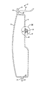
Conversely, the inner panel may be first transferred to a station where
fasteners
are coupled to the inner panel and then the inner panel including the
fasteners is
moved to the welding station for interconnection with the outer panel as
previously described.
[0003] The requirement for multiple workstations and multiple sets
of
tooling greatly increases the cost and time required to manufacture a vehicle
component. Depending on the method used to attach the fasteners, difficulties
1
CA 02668133 2009-06-03
=
707410CA
may arise in providing access to the tooling to assure proper fastener
mounting.
For example, a tubular member may require machining to provide apertures
allowing access for electrodes on one side of a resistance welded joint. The
additional machining and mechanical strength degradation may be undesirable.
[0004]
Furthermore, other fasteners may require relatively large
amounts of energy over an extended period of time to provide a desired joint
strength. One example includes attempting to laser weld nuts having relatively
large thicknesses equal to the length of a threaded aperture of the fastener.
The
time and energy required to couple the thick fastener may be prohibitive.
[0005] Attempts to couple mechanical fasteners to sheet steel via a
laser welding process have been challenging. To prevent corrosion of the
fastener and/or the substrate, a galvanized coating is often used. One known
welding attempt includes providing a fastener having a substantially smooth
planar surface abutting a substantially smooth planar surface of a galvanized
substrate. During the laser welding process, the galvanized coating boils and
zinc gas is emitted. The zinc gas is temporarily trapped between the
substantially smooth planar surfaces of the fastener and the substrate until
sufficient energy is gained for the gas to escape. Parent material of the
substrate
and/or the fastener may be ejected based on the pressure and energy provided
from the zinc gas. After the parent material is ejected, undesirable porosity
or
holes are formed requiring the assembly to be scrapped or reworked. If
ejection
of the parent material does not occur, the weld may be otherwise negatively
2
CA 02668133 2009-06-03
707410CA
affected due to the presence of the zinc gas. Accordingly, a need exists in
the
art to provide improved laser welding methods and laser welded products.
SUMMARY
[0006] A method of
manufacturing a vehicle structure including a laser
welded fastener includes providing a first panel and a second panel to be
joined
to one another, where the first panel having a predetermined thickness. A
thickness of a flange of a fastener to be welded to the first panel is
determined
based on the thickness of the first panel. Projections axially extending from
a
first surface of the flange are formed. The method also includes positioning
the
first panel in engagement with the second panel to provide access to the first
panel by a laser beam. The first panel is laser welded to the second panel.
The
projections are engaged with a surface of the first panel to space apart the
first
surface of the flange from the surface of the first panel. Laser welding is
initiated
by directing a laser beam toward one of the flange of the fastener and the
first
panel. Gas is vented from an area between the first surface of the flange and
the
surface of the first panel. The flange is laser welded to the first panel at a
location spaced apart from the projections.
[0007]
Additionally, a method of manufacturing a vehicle structure
including a laser welded fastener includes providing a panel having a
predetermined thickness and an aperture extending through the thickness. A
fastener having a threaded portion, a radially outwardly extending flange and
a
projection axially extending from a first surface of the flange is formed. The
3
CA 02668133 2009-06-03
707410CA
threaded portion of the fastener is aligned with the panel aperture. The
projection is engaged with a surface of the panel to space apart the first
surface
of the flange from the surface of the panel. Laser welding is initiated by
directing
a laser beam toward one of the flange of the fastener and the panel. Gas is
vented from an area between the first surface of the flange and the surface of
the
panel. The flange is laser welded to the panel at a location spaced apart from
the projection.
[0008] Further areas of applicability will become apparent from
the
description provided herein. It should be understood that the description and
specific examples are intended for purposes of illustration only and are not
intended to limit the scope of the present disclosure.
DRAWINGS
[0009] The drawings described herein are for illustration
purposes only
and are not intended to limit the scope of the present disclosure in any way.
[0010] Figure 1 is a cross-sectional view of an exemplary laser
welded
vehicle structure including a laser welded fastener;
[0011] Figure 1A is an enlarged view of a portion of Figure 1;
[0012] Figure 2 is a perspective view of a fastener prior to
laser
welding;
[0013] Figure 3 is a perspective view of an alternate fastener
having
radially extending ribs axially protruding from a flange;
4
CA 02668133 2009-06-03
707410CA
[0014]
Figure 4 is a flow chart depicting a method of laser welding an
automotive component;
[0015]
Figure 5 is a fragmentary cross-sectional perspective view of an
alternate fastener positioned for laser welding to a substrate;
[0016] Figure 6 is
a fragmentary cross-sectional perspective view of an
alternate fastener positioned for laser welding to a substrate;
[0017]
Figure 7 is a fragmentary cross-sectional perspective view of an
alternate fastener positioned for laser welding to a substrate; and
[0018]
Figure 8 is a fragmentary cross-sectional perspective view of an
alternate fastener positioned for laser welding to a substrate.
DETAILED DESCRIPTION
[0019]
The following description is merely exemplary in nature and is
not intended to limit the present disclosure, application, or uses. It should
be
understood that throughout the drawings, corresponding reference numerals
indicate like or corresponding parts and features.
[0020]
With reference to Figure 1, an exemplary laser welded door is
identified at reference numeral 10. It should be appreciated that door 10 is
merely exemplary and that any number of laser welded structures may be
constructed in accordance with the teachings of the present disclosure. Door
10
includes a stamped outer panel 12 and a stamped inner panel 14. Outer panel
12 includes a first upper flange 16 and a first lower flange 18. Inner panel
14
includes a second upper flange 20 and a second lower flange 22. Outer panel
5
CA 02668133 2009-06-03
707410CA
12 and inner panel 14 are formed independently from one another and
subsequently positioned in a laser welding workstation as shown in Figure 1.
Once outer panel 12 is positioned relative to inner panel 14 in the desired
location, a laser weld is formed by emitting a beam from a laser 24. The laser
welding is accomplished by positioning laser 24 proximate an outer surface 26
of
second upper flange 20. In similar fashion, second lower flange 22 is laser
welded to first lower flange 18 by directing a beam emitted from laser 24 at
an
outer surface 28 of second lower flange 22.
[0021]
In the same work cell, a fastener 30 is fixed to inner panel 14.
This process is accomplished by first positioning fastener 30 in alignment
with an
aperture 32 extending through inner panel 14. In the example shown in Figure
1,
fastener 30 is a threaded nut including a cylindrically shaped body 34 and a
radially extending flange 36. A threaded bore 38 extends through body 34 and
flange 36. Threaded bore 38 is positioned in alignment with aperture 32 such
that an externally threaded fastener (not shown) may be engaged with threaded
bore 38 and extend through inner panel aperture 32.
[0022]
As shown in Figure 2, a plurality of projections 40 axially extend
from a first surface 42 of flange 36. Flange 36 includes an opposite surface
43.
Projections 40 are substantially cylindrically shaped and circumferentially
spaced
apart from one another. Each projection 40 includes an end face 44 spaced
apart from surface 42 a common distance. Each projection 40 is relatively
small
such that each end face 44 functions to provide substantially point contact
with
an outer surface 46 of inner panel 14. As such, projections 40 define a plane
on
6
CA 02668133 2009-06-03
707410CA
which fastener 30 contacts inner panel 14. Projections 40 may be alternatively
shaped as hemispheres, cones or any other suitable shape.
[0023]
It should be noted that projections 40 assure that a space exists
between surface 42 of fastener 30 and surface 46 of inner panel 14 prior to
laser
welding. Projections 40 do not provide electrical pathways for current to flow
during welding. Laser welding of flange 36 to inner panel 14 occurs at
locations
other than through projections 40. As such, the spacing between surface 42 and
surface 46 is minimized to facilitate robust laser welding. On the other hand,
projections 40 must extend a distance sufficient to allow gaseous zinc to
escape
from the galvanized surface of inner panel 14 and/or fastener 30 during laser
welding. It has been found through experimental testing that a spacing of
approximately 0.1 mm between surface 42 and surface 46 meets these opposing
concerns.
[0024]
Figure 3 depicts an alternative fastener 50 having a flange 52
radially extending from threaded central aperture 54. A plurality of radially
extending projections 56 axially extend from a surface 58 of flange 52.
Projections 56 may be shaped as ribs having substantially constant or varying
thickness in lieu of the projections 40 previously described. Projections 56
perform the same function as projections 40 in that they space surface 58 of
fastener 50 from surface 46 of inner panel 14 to allow gas to escape from
between the surfaces during the laser welding process.
[0025]
The work cell for assembling door 10 is configured to reliably
and quickly laser weld outer panel 12 to inner panel 14 as well as laser weld
at
7
CA 02668133 2009-06-03
707410CA
least one fastener 30 to inner panel 14 or any other panel that may be
subsequently laser welded to outer panel 12 or inner panel 14. This goal may
be
accomplished by implementing a process of properly configuring fastener 30,
outer panel 12 and inner panel 14 as defined in the flow chart presented in
Figure 4. To minimize the time required to weld the various components to one
another, fastener 30 is optimized in size, shape and material to cooperate
with
the substrate to which it is being laser welded. In this instance, fastener 30
is
laser welded to inner panel 14. The process begins at block 100 where a
thickness of the substrate or inner panel 14, and a target joint strength are
provided. At block 102, the size and thread length, if applicable, of fastener
30
are determined based on target joint strength. For example, a known joint
clamp
load may be desired to be provided to mount an accessory to inner panel 14.
Accordingly, a fastener grade and diameter may be selected based on the target
joint strength. A minimum thread engagement may also be determined and used
to determine the thread length of threaded bore 38. The length of the threaded
body portion may also be determined by calculating a length necessary to
minimize the likelihood of the spatter produced by the laser welding process
from
contacting the threads.
[0026]
At block 104, the material used to construct fastener 30 is
determined based on weldability to the substrate as well as the target joint
strength. At block 106, the outer diameter of flange 36 is determined based on
a
predetermined pull-through strength for the joint. The pull-through strength
relates to an amount of force required to pull fastener 30 through inner panel
14.
8
CA 02668133 2009-06-03
707410CA
As the diameter of flange 36 increases, so does the pull-through strength. The
flange diameter determination may also be based on providing adequate access
for the laser. As the flange diameter increases, the angle or weld access view
point, at which the laser beam may be applied also increases. Movement of the
laser beam may be minimized or clear access to the flange may be provided by
increasing the flange diameter.
[0027] At block 108, a thickness of flange 36 is determined based on
the thickness of the substrate. A robust laser weld between flange 36 and
inner
panel 14 may be produced in a time efficient manner by forming the thickness
of
flange 36 to be substantially the same as the thickness of inner panel 14 at
the
location of the laser weld. Other thicknesses may also be used to provide the
target joint strength. However, flange thicknesses substantially exceeding the
thickness of the substrate will require more time and energy to weld through
the
fastener flange and produce a satisfactory laser weld.
[0028] Block 110
provides the step of forming fastener 30 per the
characteristics previously determined as well as forming projections 40
axially
extending from flange 36. At this time, the geometry of fastener 30 is
defined.
[0029]
At block 112, inner panel 14 is positioned relative to outer panel
12 such that second upper flange 20 engages first upper flange 16. Second
lower flange 22 also engages first lower flange 18. Outer panel 12 and inner
panel 14 are oriented within the work cell to provide access to inner surfaces
26
and 28 by laser 24. At block 114, outer panel 12 is laser welded to inner
panel
9
CA 02668133 2009-06-03
=
707410CA
14 along the pair of upper flanges as well as the pair of lower flanges
previously
described.
[0030]
Fastener 30 is positioned to engage projections 40 with outer
surface 46 of inner panel 14 at step 116. Optimally, outer panel 12 and inner
panel 14 will not be translated, rotated or otherwise moved from their
previous
positions when the upper and lower flanges were welded to one another. In this
manner, accurate positioning is maintained, extra transfer tooling is not
required,
and no time is spent in transferring or repositioning the substrate prior to
laser
welding fastener 30 thereto. It should be appreciated that the positioning
step
defined in block 116 may be achieved by placing fastener 30 over a pin
aligning
threaded bore 38 with aperture 32. Because electrical current does not pass
through projections 40, a clamping load need not be imparted to assure that
proper electrical pathways exists such as prior to resistance welding. On the
contrary, the present method not only reliably and quickly secures fastener 30
to
inner panel 14, but does so without deforming inner panel 14 via previously
known crimping or clamping methods such as known in the resistance welding
art.
[0031]
At block 118, a laser beam emitted from laser 24 is directed to
surface 43 of flange 36 to initiate laser welding fastener 30 to inner panel
14. At
block 120, zinc gas is vented from the area between surface 42 and surface 46
through the vent passages defined by projections 40. At block 122, laser
welding
of fastener 30 to inner panel 14 is completed by directing the beam emitted
from
laser 24 along a predetermined path on surface 43 of flange 36. It should be
CA 02668133 2009-06-03
707410CA
appreciated that the laser may be intermittently powered to provide a number
of
spaced apart laser welds. Alternatively, the laser may be continuously powered
such that an uninterrupted ring-shaped weld is formed between flange 36 and
inner panel 14.
[0032] Figure 5
depicts an alternate fastener 150 having a first
cylindrical body portion 152 and a second cylindrical body portion 154
extending
in opposite directions from a central flange 156. A first plurality of
projections
158 axially extend from flange 156 in the same direction as first body portion
152.
A second plurality of projections 160 axially extend from flange 156 in an
opposite direction. Fastener 150 is symmetrically formed such that second body
portion 154 or first body portion 152 may be positioned within an aperture 162
formed in a substrate 164. This arrangement provides an increased length for a
threaded bore 166 extending through fastener 150.
[0033]
Figure 6 provides another alternate fastener identified at
reference numeral 200. Fastener 200 is substantially similar to fastener 150
except that projections 158 and 160 are replaced with substantially continuous
circumferentially extending rims 202, 204. Rim 202 is formed at the perimeter
of
a flange 206 and axially extends from a first surface 208 of flange 206. In
similar
fashion, rim 204 is formed at the outer circumferential limit of flange 206
and
axially extends from a second opposite surface 210 of flange 206. Rims 202 and
204 may be simultaneously formed during a cold heading or roll forming
operation. Each of a first body portion 212, flange 206, a second body portion
214, rim 202 and rim 204 are integrally formed with one another as one piece.
11
CA 02668133 2009-06-03
707410CA
Fastener 200 is also symmetrical such that either of first body portion 212 or
second body portion 214 may be positioned within an aperture 216 extending
through a substrate 218. Rims 202, 204 also function to form a seal between
fastener 200 and a surface 220 of substrate 218. The laser weld may form a
hermetic seal. A leak proof joint results. During laser welding, zing gas
escapes
from between surface 210 and surface 220 through a gap formed between
second body portion 214 and the walls of aperture 216 in which fastener 200 is
positioned.
[0034]
Figure 7 provides another alternate fastener 250 laser to be
welded to a substrate 252. Fastener 250 is substantially similar to fastener
30
previously described.
As such, like elements will retain their previously
introduced reference numerals including a prime suffix. Fastener 250 differs
from fastener 30 in that another set of projections 254 axially extend from
surface
43'. By positioning projections 254 at this location, fastener 250 may be
inverted
relative to substrate 252 such that body 34' is positioned within an aperture
256
extending through substrate 252. Fastener 250 may also be positioned in a non-
inverted fashion as shown in Figure 1 if desired.
[0035]
Figure 8 shows an externally threaded fastener 300 for laser
welding to a substrate 302. Fastener 300 is shaped as a cap screw having a
shank 304 with a threaded portion 306. A radially enlarged head 308 is
integrally
formed with shank 304. A stepped shoulder 310 may or may not be present. A
first uninterrupted circumferential rim 312 axially extends from a surface 314
of
head 308. A second uninterrupted circumferentially extending rim 316 axially
12
CA 02668133 2015-10-28
707410CA
=
extends from a surface 318 of head 308. Rims 312, 316 may be formed by
rolling or peening operations. Due to the presence of rim 312 and rim 316,
fastener 300 may be laser welded to substrate 302 in the orientation depicted
in Figure 8 or may alternatively be inverted such that surface 314 of head 308
is laser welded to a surface 320 of substrate 302. During laser welding, zing
gas escapes from between surface 318 and surface 320 through a gap formed
between shank 304 and the walls of an aperture 322 in which fastener 300 is
positioned.
[0036] Furthermore,
the foregoing discussion discloses and
describes merely exemplary embodiments of the present disclosure. One
skilled in the art will readily recognize from such discussion, and from the
accompanying drawings and claims, that various changes, modifications and
variations may be made therein without departing from the scope of the
disclosure as defined in the following claims.
13