Note: Descriptions are shown in the official language in which they were submitted.
CA 02668332 2009-04-29
WO 2008/053178 PCT/GB2007/004108
1
Multi-Dosing Detergent Delivery Device
The invention relates to a multi-dosing detergent
delivery device. The device is particularly for
dispensing said detergent into an automatic dishwashing or
washing machine over a plurality of washing cycles.
In automatic dishwashing machines,' the detergent,
whether in powder, tablet or gel form, is usually filled
manually by the user into the machine, in particular into
a detergent holder, before each dishwashing operation.
This filling process is inconvenient, with the
problem of exact metering of the detergent and possible
spillage thereof, for powder and gel detergents. Even
with detergents in tablet form, wherein the problem of
accurate dosing is overcome, there is still the necessity
of handling the dishwashing detergent every time a
dishwashing cycle is started. This is inconvenient
because of the usually corrosive nature of dishwasher
detergent compositions.
A number of devices are known for holding unit doses
of a detergent composition or additive, such as detergent
tablets, and for dispensing of such unit doses into a
machine.
WO 01/07703 discloses a device for the metered
release of a detergent composition or additive into a
dishwashing machine having a number of separate sealed
chambers for holding the detergent composition or additive
and means for piercing the chambers, activated by
conditions within the machine.
CA 02668332 2009-04-29
WO 2008/053178 PCT/GB2007/004108
2
WO 03/073906 discloses a free standing device for
dispensing multiple doses of detergent into a dishwasher.
The device has a plate-like construction. A round blister
5. pack having a plurality of doses arranged around its
periphery is loaded into the pack. A winder is then
rotated to load mechanical energy into the device
sufficient to dispense more than one dose of detergent. A
thermally operated latch then moves when the device is
subjected to the e levated temperatures within the
dishwasher and, in cooperation with a ratchet mechanism,
moves the blister pack so that the next dose of detergent
is ready for dispensing. In order to dispense the'
detergent, either the blister pack is pierced, or the dose
is ejected from its compartment within the blister pack.
WO .03/073907 discloses a similarly shaped free
standing dispensing device. In order to dispense
detergent, a lever is manually operated to move a blister
pack either to eject the detergent from a compartment
within the blister pack, or to pierce the blister pack. A
door or flap initially prevents wash liquor within the
machine from accessing the exposed detergent. A bi-
metallic strip is provided to move the door or flap when
the device is exposed to the elevated temperatures during
a washing cycle to allow access of the wash liquor to the
exposed detergent thereby dispensing the detergent to the
machine.
One problem with temperature activated advancing of
detergent doses is that a dishwasher machine, for instance
may during a single cycle include intermediate cycles so
that temperature may rise in an initial part of a cycle
CA 02668332 2009-04-29
WO 2008/053178 PCT/GB2007/004108
3
and a dose of detergent administered, a drop in
temperature and a subsequent rise during the same cycle
may then cause a dose to be administered twice.
It is therefore an aim of preferred embodiments of
the invention to avoid or reduce the chances of occurrence
of such double dosing.
Other problems are associated with automatic dosage
mechanisms and it is a further aim of preferred
embodiments to address one or more of such problems as
herein discussed.
In accordance with the above, the present invention
is related to refining an automatic indexing mechanism for
automatically advancing between doses of detergent.
According to the present invention there is provided a
multi-dosing detergent delivery device, the device
comprising a housing for receiving therein a cartridge
ha'ving a plurality X of chambers each accommodating a
detergent composition, a directing means to direct, in
use, wash liquor selectively into a chamber of the
cartridge to contact the detergent composition therein and
an outlet to allow the detergent loaded wash liquor to
exit the device, wherein the device further comprises
indexing means for automatic movement of said cartridge,
in use, relative to said directing means during and
subsequent to a wash cycle so as to cause a neighbouring
chamber to be in an exposed, ready to be used, position
prior to a next washing cycle.
CA 02668332 2009-04-29
WO 2008/053178 PCT/GB2007/004108
4
Preferably, said housing is substantially cylindrical
and each compartment occupies a nominal 360/X angular
degrees of space.
Preferably, during a heating phase of a washing cycle
said indexing rrieans is arranged to rotationally advance
said cartridge relative to said housing by a percentage Z%
of said nominal 360/X angular degrees and, during and
subsequent to a final cooling phase of a washing cycle to
10' further rotationally advance said cartridge relative to
said housing by a percentage (100-Z)o of said nominal
360/X angular degrees.
Suitably, Z is in the range of 10 to 30 and, most
preferably, is substantially 20 and X is 12, such that in
the preferred device there are 12 chambers, each occupying
30 degrees of rotational space and movement during heating
advances the cartridge by 6 degrees, whereas movement at
the end of a washing cycle is by 24 degrees.
P- referably, said indexing mechanism contains a
thermally reactive element. Whilst the thermally reactive
element may be any of a memory metal/memory alloy, thermal
bimetal, bimetal snap element or shape memory polymer, it
is most preferably a wax motor. The thermally reactive
element is preferably designed to react at temperatures
between 25 C and 55 C (more preferably 35 C to 45 C. The
thermal element preferably has a hysteresis effect. This
delays the operation of the thermal element to ensure that
the device is not reset during the early part of the wash
cycle of the machine, but is only reset once the machine
has carried out the full washing process.
CA 02668332 2009-04-29
WO 2008/053178 PCT/GB2007/004108
Said indexing means preferably comprises a wax motor
which expands a wax canister during a heating phase of
a washing cycle and contracts as it cools during and
5 subsequent to a final cooling phase of said washing
cycle. Said indexing means preferably further
comprises a gearing mechanism to convert linear motion
of said wax motor to rotational movement of ' said
cartridge relative to said housing.
Preferably, said gearing mechanism comprises first and
second rotational elements. capable of movement in a
first rotational direction in a first plane and a
linear element which is capable of linear movement in a
.15 second plane.
Preferably, in a cold state of said wax motor a first
gear portion of said linear element is fully meshed
with a gear portion of said first rotational element
and in a hot state of said wax motor a second gear
portion of said linear element is fully meshed with a
gear portion of said second rotational element.
Preferably, both said first and second rotational
elements are linked to said cartridge ' to impart
rotational movement to it.
Preferably, during a heating cycle said linear element
disengages from said first rotational element and moves in
a first linear direction to engage with said second
rotational element, and wherein as said linear element
engages with said second rotational element a first phase
of further motion in said first linear direction imparts a
CA 02668332 2009-04-29
WO 2008/053178 PCT/GB2007/004108
6
rotational movement in a first rotational direction to
said second rotational element.
During a second phase of said heating cycle further
movement of said linear element in said first linear
direction preferably causes no further rotational
direction to said second rotational element.
Preferably, at the end of a washing cycle, during a
cooling cycle thereof said linear element disengages from
said second rotational element and moves in a second
linear direction opposite to said first linear direction
to engage with said first rotational element, and wherein
following initial engagement of said linear element with
said first rotational element further motion in said
second linear direction imparts a rotational movement in
the first rotational direction to said first rotationa.l
element.
Most preferably, said indexing mechanism comprises a
wax motor and a gearing mechanism to translate movement of
said wax motor to' relative rotational movement between
said cartridge and said housing and to cause movement
between a state where a first of said X chambers is fully
exposed to allow wash liquor to enter it at the start of a
first complete washing cycle and wherein following
completion of said first washing cycle a second,
neighbouring one of said X chambers is fully exposed to
allow wash liquor to enter it at the start of the next
complete washing cycle.
CA 02668332 2009-04-29
WO 2008/053178 PCT/GB2007/004108
7
Preferably, the device is provided with a funnel
leading to the directing means and said funnel is part of
a lid of said device.
The first with a thermal element may be designed'such
that it has a hysteresis (time and/or temperature based).
Thus the thermal element is activated at the start of the
wash cycle. However, (for a temperature hysteresis
effect) the thermal element is designed such that the
decreasing temperature between the wash cycle(s) and the
rinse cycle(s) is not sufficient to de-activate the
element, and so re-activation at the start of the rinse
cycle cannot occur. In this case the thermal element
preferably has an activation temperature of around 38 C to
45 C and a de-activation temperature of around 25 C to
33 C.
For a time hysteresis effect the thermal element is
designed such that it can only be activated once during a
dishwasher cycle. Typically from 30 minutes to 2 hours.
A simulated temperature hysteresis effect may be
achieved by providing a jacket around the thermal element.
The jacket is intended to fill with hot wash liquor from
the wash cycle. The jacket preferably has a small outlet
aperture. The small outlet aperture means that during the
relatively cool period between the wash and rinse cycle(s)
the jacket retains the majority of the hot wash liquor,
meaning that the thermal element is not de-activated
during this cooler period.
For the wax motor the melting and solidification
behaviour of the wax itself can be used for the
CA 02668332 2009-04-29
WO 2008/053178 PCT/GB2007/004108
8
hysteresis, because certain wax types show slow
solidification compared to melting.
Also for the wax motor the hysteresis effect may be
achieved by a water collector (having a small/slow water
release aperture) which prevents the wax motor from the
second movement by the weight of the collected water. The
water collector preferably empties over 20 minutes to an
hour.
Preferably, the cartridge is removable from the
device to allow the cartridge to be sold as a replaceable
compbnent which is inserted into the. device in which the
directing means is provided. The cartridge may comprise
the combination of a refill holder and a refill and, the
refill may be a disposable item.
The device is preferably for' use in an automatic
dishwasher. Accordingly the detergent most preferably
comprises an automatic dishwasher detergent. Examples of-
which include conventional detergents, and the `2-in-l'
and 13-in-1' variants. Most preferably the detergent
comprises a=solid. In the context of the present
invention the term solid can be taken to include
solidified gels as well as conventional solid materials
(such as compressed particulate materials and solidify
molten/cross linked materials).
The detergent formulation typically comprises one or
more of the following components; builder, co-builder,
surfactant, bleach, bleach activator, bleach catalyst,
enzyme, polymer, dye, pigment, fragrance, water and
organic solvent.
CA 02668332 2009-04-29
WO 2008/053178 PCT/GB2007/004108
9
Optionally the detergent comprises a detergent
additive. It will be appreciated that a detergent
additive when compared to a detergent may be required
during a different section of the dishwasher wash cycle
(e.g. such as the rinse cycle for a rinse aid detergent
additive).
The detergent may be added to the cartridge by any
suitable method. The detergent may be added to the
cartridge manually, by casting or by injection moulding.
A suitable injection moulding process is described in
British Patent Application GB-A-2 406 821 and WO
2005/035709.
Preferably the device includes an indication
mechanism to show how many chambers of the cartridge
remain (i.e. are still full of detergent) or how many'of
the chambers have been used up so that a user has an idea
of when a replacement is required. A preferred form of an
indication mechanism comprises a marking on the cartridge
which can be viewed by a consumer. The marking may
comprises a series of numerals arranged in association
with one or more of the chambers of the cartridge. Such a
marking may require a= window in order to be viewed by a
consumer. Optionally the marking may be associated with a
fixed marker so that the relevant part of the marking is
clearly indicated.
Optionally the marking may employ a colour scheme
(e.g. along the lines of a traffic light system with red
meaning that only a small number of chambers remain,
CA 02668332 2009-04-29
WO 2008/053178 PCT/GB2007/004108
yellow an intermediate number and green a large number of
chambers remain.
Examples of devices in accordance with the present
5 invention will now be described with reference to the
accompanying drawings, in which:
Figures 1(a), 1(b) and 1(c) are perspective
assembled, perspective exploded and internal perspective
10 views of a housing part and lid of a first embodiment of a
detergent dispensing device in accordance with the present
invention;
Figures 2(a) and (b) are schematic perspective views
from above and from below showing a refill holder for use
with a device in accordance with the present invention;
Figures 3(a),and 3(b) show a refill cartridge for use
with the refill holder of figures 2(a) and (b), whilst
figure 3(c) shows a single chamber of a refill cartridge.
Figures 4(a) and 4(b) are perspective exploded and
perspective partial assembly views of an automatic
indexing mechanism for use in accordance with a device
according to the present invention;
Figures 5 shows in perspective cross-sectional view
the automatic indexing mechanism of figure 3;
Figures 6(a) to 6(d) show the various states of the
indexing mechanism of figures 4 and 5 as temperature
within, an appliance utilising the device changes during a
dishwashing cycle;
CA 02668332 2009-04-29
WO 2008/053178 PCT/GB2007/004108
11
Figure 7 shows a graph of temperature fluctuations
over time during a typical dishwashing cycle and of the
variations in activation state of a wax motor canister
during the same period of time.
Figures 1(a), 1(b) and 1(c) show respectively
perspective assembled, perspective exploded and internal
perspective views of detergent dispensing device 1
comprising a housing 2 and a lid 3. The housing 2 has an
indexing mechanism 100 housed within it and described
later. The lid 3 has a window 32 to allow a user to see
by means of a visual indicator a number of washes used or
remaining for use with the device and also has directing
means comprising an aperture 34 for directing wash
liquor/water to the interior of the housing. The lid 3
has a general funnel like appearance to facilitate the
collection of wash liquor/water available to the directing
means.
The housing= 2 is arranged to receive a refill holder
4 as shown in figures 2(a) which shows a refill holder in
front perspective view and figure 2 (b) which shows the
holder in bottom perspective view. The refill holder 4
comprises a plurality of dividing fingers 5 emanating from
a central hub 6 and has a base 7 featuring a number of
apertures 8 and lower location slots 9. Internally of the
hub 6, there are formed one or more upper locating tabs 10
(four shown in the figure), whilst externally and at a
central portion thereof there is provided numbering from 1
to 12 representing the number of washing cycles that an
associated refill may have undergone or have remaining.
The window 32 of the lid has a transparent=portion that
CA 02668332 2009-04-29
WO 2008/053178 PCT/GB2007/004108
12
is, in use, aligned with the relevant sector of the
numbered area.
The refill holder 4 is, in use, positionable within
the housing 2 and the hub 6 has a hollow formation to co-
operate with, and fit over, a central shaft 120 of the
indexing mechanism 100 as will be described later.
The fingers 5 are arranged to co-operate with and
register with internal spaces formed between parts of a
disposable refill package 200 such as the one shown in
figures 3(a) and 3(b) and having individual chambers 210
as shown in figure 3(c). The refill package 200 is a
cartridge that comprises a plurality of like chambers 210,
and has a roll formation. The chambers 210.are separate
from each other and comprise plastic sleeve or blister
packages. The chambers 210 are spaced apart, having gaps
between them that are apt to be engaged by the fingers 5
of the refill holder 4. Each chamber has an upper opening
220 and a lower opening 240 that is, in use, in register
with one of the apertures 8 of the refill holder. Each
chamber 210 is filled with sufficient cleaning composition
for the completion of one dishwasher cycle. The contents
of the chambers 210 are preferably in solid form and,
therefore there is no problem with inadvertent spillage.
There is also a central gap 250 in a central hub area that
facilitates the placement of the refill 200 onto the
refill holder 4.
Referring now to figures 4(a) and 4(b) there is shown
an indexing mechanism for automatically rotating the
refill holder 100 and refill 200 of the device 1 relative
to the housing 2 and lid 3.-
CA 02668332 2009-04-29
WO 2008/053178 PCT/GB2007/004108
13
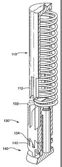
The indexing mechanism 100 comprises a shaft 110, a
spring 120, a cursor element 130, a cam 140 and a
thermally reactive element that is preferably a wax motor
150.
The shaft 110 is hollow and receives the other
components of spring, 120, cursor 130, cam 140 and wax
motor 150 therein.
The shaft 110 has a closed end region 114 for
providing a seat to the spring 120 and, approximately mid-
way down a length of the shaft 110 there are formed
internally a plurality of spaced apart downwardly
depending straight parallel grooves 112, each of these
grooves has a sloping lowermost portion as will be
described presently.
The cursor 130 is locateable within the shaft 110
and, at its upper most portion provides a lower seating
for the spring 120. It also has moulded thereon an upper
and lower set of gear teeth 132, 134.
Cam element 140 is arranged for selective co-
operation with the cursor element 130 and it too has an
upper set of gear teeth 142 and has locating tangs 144 to
locate it positively in use against refill holder 4. The
cam element 140 has a central aperture to allow the wax
motor element to sit within it.
Wax motor 150 comprises a wax can and a piston.
Essentially, as wax is heated it expands and pushes
against the piston, as it cools down, the wax contracts
CA 02668332 2009-04-29
WO 2008/053178 PCT/GB2007/004108
14
and, aided by spring action of the spring 120, the piston
returns to its original position. In the device of the
preferred embodiment, the wax motor sits at the bottom of
the shaft 110 in the space provided by the central
aperture of the cam element 'and the piston acts so as to
cause the cursor 130 to rise and fall as appropriate
during a heating/cooling cycle.
The inter-relation between all of the parts mentioned
up to now will next be discussed.
Firstly, it will be appreciated that the housing 2,
indexing mechanism 100 and the refill holder 4 are readily
assembled into a single unit: Referring to Figure 5,
there is shown in a partial cut-away form a part of the
shaft 110, the spring 120, cursor 130 and cam 140 all
seated within the shaft 110. Here, the spring 120 seats
against the internally closed top end of the shaft 120 and
against the top of the cursor 130, whilst the wax motor
140 is positioned within the central aperture of the cam
140 and, at its lower end bears against a part of the base
of the housing 2 and at its upper end against the cursor
130. The refill holder 4 is placed over the shaft 110 of
the indexing mechanism and is located thereon by co-
operation of its locating tabs 10 with corresponding
formations in the form of locating slots 116. The refill
holder also locates to the cam element 140 by co-operation
between slots 9 and tangs 144, so that the shaft 110 and
the cam 140 are locked to the refill holder 4.
Although not shown in the figures, the cursor element
130 is'constrained such that it cannot rotate with respect
,to the holder 2, but it can be displaced in the vertical
CA 02668332 2009-04-29
WO 2008/053178 PCT/GB2007/004108
plane as such, it constitutes a linear element. The
refill holder 4 on the other hand, is (once a refill 200
has been associated with it and the device 1 has been
closed by associating the lid 3 with the housing 2)
5 constrained such that it cannot be significantly displaced
in a vertical direction, but is capable of rotation within
the housing 2 and as such constitutes a first rotational
element.
10 There will now be described, with reference to the
figures the use of the device and a cycle which takes
place upon heating of an assembled device/refill
combination.
15 When the user first receives the device, the user will
note that the lid of the device 3 includes a window 32,
through which one of the numerals on the number dial 6 is
visible. For a new device, the preferred number that the
user will see is number "1". This indicates to the user
that the device is a new device, and is ready for its
first cycle within the dishwashing machine.
Generally, the device will include a clip or mounting
device (not shown), which will permit the user to attach
the device to the upper wire basket of a dishwasher,
preferably in a discrete location such as a corner. The
user then need only close the door of the dishwasher and
select an appropriate programme.
The device as,shown in the figures hosts twelve separated
doses of detergent, within twelve individual chambers.
CA 02668332 2009-04-29
WO 2008/053178 PCT/GB2007/004108
16
In the start position for the very first wash, an aperture
34 in the lid 3 is generally aligned with opening 220 of
the refill 200. It should be noted here that lower
opening 240 (which in general is of an identical size to
upper opening 220) is an outlet hole, whilst upper opening
220 is an inlet hole, so that water dispensed by a
dishwasher during a washing cycle and collected by the lid
3, may wash through the exposed compartment 210, and enter
into the dishwasher carrying dissolved or particulate
cleaning composition from the chamber 210. The lower
opening 240 need not be precisely aligned with a
particular outlet hole formed in the housing 2, but
instead the housing 2 may simply have one or more drainage
holes which, under gravity, will allow the water and
cleaning composition to exit from the device 1.
Indexing of the refill holder 4, and its associated refill
package 200 so that a next chamber 210 is ready during a
second washing cycle is accomplished by means of the
indexing mechanism 100.
The general principles promoting the indexing of the
refill 200 and holder 4, are that the indexing mechanism
100 includes a wax motor element 150. This wax motor
element 150, basically consists of a wax cam and piston.
In preferred embodiments, the wax motor delivers up to 300
N of force. When the water in the dishwasher gets warm,
the wax in the cam starts to expand and pushes the piston
out of the wax cam. When the dishwasher cools down,
strong spring 120 pushes the piston back into the wax can.
In testing of some embodiments of the invention, there was
incurred a problem when a dishwasher included cool
CA 02668332 2009-04-29
WO 2008/053178 PCT/GB2007/004108
17
intermediate cycles, as well as a hot cycle. Here, there
was a risk that the wax motor might rotate the refill
cartridge, not only to a next chamber 210, but also to the
one after and so on and a large degree of wastage of
cleaning composition could occur, leading to a major
disadvantage. This problem has been overcome by utilising
a wax composition having a degree of hysteresis built in.
In other words, such a "lazy" wax composition which takes
some time to solidify when cooled down, can be enough to
"survive" short cold intermediate cycles without possible
double or triple actuations. Other factors involved in
providing a good solution to this problem involve
providing a reasonable amount of insulation to the
canister including the wax motor 150, so that the wax
motor cools slowly.
Up and down movement of the piston of the wax motor 150 is
trarislated into a rotation of the refill cartridge 200 and
its holder 4, by means of a gearing system comprising the
cam, cursor, and shaft of figures 4(a) and (b).
Figure 5 shows schematically a start position of the
gearing system, in which the linear element, the cursor
130, is meshed with a first rotational element in the form
of cam element 140, but separated from contacting with the
interior of the shaft 110 (which forms a second rotational
element). In otYier words, the upper set of gear teeth 132
of the cursor 130 are completely separated from the
parallel grooves 112 forming gear teeth of the shaft 110,
but the lower set of gear teeth 134 of the cursor 130, are
meshed with the gear teeth 142 of the cam 140.
CA 02668332 2009-04-29
WO 2008/053178 PCT/GB2007/004108
18
Here, it should be noted that each of the portions acting
as gears, include sloping teeth, for promoting gear
meshing in a particular rotational direction, and gap
portions for ensuring positive engagement in particular
positions.
In the state shown in Figure 5, there is no heat applied
to the wax motor 150. However, within the dishwasher
cycle, the conditions applied involve rising temperature
sections, during a given washing programme, followed by
cooling conditions. The functioning of the wax motor
mechanism 150; and the various cam 140, cursor 130, and
shaft 110, motions will now be described in particular with
reference to Figures 6(a). through Figure 6(d).
Figure 6(a) shows what happens during a first part of a
heating cycle. During this heating cycle, the piston of
the wax motor 150 extends so as to raise the cursor
element 130, and disengage the lower gear teeth 134 of the
cursor 130, from the gear teeth 142 of the cam 140.
Indeed, as the cursor element 130 rises, the lowermost
exten.t of the cursor 130 becomes completely clear of the
cam element 140. At some point, during the heating cycle,
sloping surfaces of the upper set of gear teeth 132 of the
cursor 130, come into contact with sloping surfaces at the
end of gear teeth provided by the formations 112
internally of the shaft 110. It.is to be noted here that
the sloping surfaces co-operate in.such a manner that, as
the cursor 130 may only move in the vertical plane, but
the shaft 110 cannot move in the vertical plane, but
instead is allowed to move rotationally in the horizontal
plane, the shaft 110 is forced to rotate in the direction
dictated by the sloping surfaces. In this way, as
CA 02668332 2009-04-29
WO 2008/053178 PCT/GB2007/004108
19
temperature rises still further, the point shown in Figure
6(b) is reached, where a partial rotation of the shaft
110, and thereby of the associated refill holder 4, and
refill 200 has occurred and, further heating simply
results in the cursor 130 rising still further, and its
upper gear teeth 132, which are elongated, rise vertically
into gaps formed between the gear teeth 112. Therefore,
during a heating cycle, a controlled amount of rotation
occurs, dictated by the formation of the gearing of the
upper teeth 132, and the formations 112 (which for reasons
which we shall explain later gives a 6 rotation during a
heating cycle) is facilitated and, thereafter, further
heating does not cause further rotation, but insteacl
causes greater meshing between the gear teeth 132, and the
gaps between formations 112 on the shaft.
Thereafter, during a, prolonged cooling cycle, the
procedures shown in Figures 6(c) and 6(d) occur. Firstly,
during the cooling, the cursor 132 descends vertically, as
the piston of the wax motor 150, retracts under action of
the spring 120. Eventually, the cursor pulls clear of the
formations 112 of the shaft 110. Then, during a final
phase of the cooling cycle, the lower set of teeth 134 of
the cursor 130, come into contact with the gear teeth 142
of the cam 140. Here, it will be noted that both the cam
140 and the shaft 110 are linked to motion of the refill
holder 4, and refill 200, and therefore the cam 140 also
underwent the 6 rotation undergone during the heating
cycle. Consequently, when the lower set of gear teeth 134
descend to meet the gear teeth 142 of the cam 140, they
are not aligned, as they previously were. As the sloping
surfaces formed on the top of the gear teeth 142, and on
the base of the lower set of gear teeth 134, come into
CA 02668332 2009-04-29
WO 2008/053178 PCT/GB2007/004108
contact with each other a rotational movement of the shaft
110, refill holder 4 and refill 200 is caused. Here, the
gearing of the sloping surfaces of the meshing teeth, are
arranged so as to bring about a 24 rotation (again for
5 reasons which will be described later) So that in the
eventual position shown in Figure 6(d) the lower set of
gear teeth 134, are fully meshed with the gear teeth 142
of the cam 140. Again, it is of course noted that the
cursor 130 is constrained to movement within the vertical
10 plane, whilst the cam 140 and shaft 110, which are
interlinked by the refill holder 4, are constrained to
movement rotationally, within the horizontal plane.'
From the above description, it can be seen that during any
15 given washing cycle, heating up of the wax canister
forming the wax motor 150, causes extension of a piston of
the wax motor 150, and brings about vertical motion of the
cursor 130. This vertical motion is translated into
horizontal rotational movement of the shaft by a first
20 amount during the heating cycle, and then by a second
amount, at the end of a cooling cycle. By selection of an
appropriate wax within the canister, and by ensuring that
gaps between gear teeth (and in particular the upper set
of gears provided between the cursor 130 and the
formations 112 of the shaft 110), are sufficiently
elongated so that any cooling during intermediate washing
cycles, does not promote sufficient retraction of the
piston 150 under spring action 120 to cause any early
meshing of the lower set of gear teeth 134, and the gear
teeth 142 of the cam 140. Thereby, only at the end of a
washing cycle, do these latter set of teeth mesh, and
promote the further rotational movement.
CA 02668332 2009-04-29
WO 2008/053178 PCT/GB2007/004108
21
The above process is illustrated schematically in Figure
7, which shows a possible scenario of a washing cycle.
In the graph of Figure 7, the upper line represents
temperature variation over time, the intermediate solid
line illustrates the expansion and contraction of a
preferred wax composition over time, whilst the lower line
(shown hatched) illustrates the expansion and contraction
of a different wax composition. The preferred wax
composition will be referred to as 36-38 C wax, whilst the
non-preferred composition will be referred to as the 38-
42 C wax.
It will be appreciated that insulation of the wax motor
150, means that tub temperatures are not immediately
presented to a given wax motor, as they are not felt
immediately by the wax within the wax motor. Thereby,
looking at the preferred wax composition, it can be noted
that once a tub temperature of 48 C has been reached
during a given washing cycle, the piston of the wax motor,
may be started to be urged upwardly by the expanding wax,
until, it reaches a fully expanded position. The degree
of insulation provided to the wax within the wax motor
150, and the use of a so-called "lazy" composition, means
that even though the temperature within the tub falls
during an intermediate cool cycle to be below a nominal
36 C temperature level, this does not translate during the
short period for which it occurs (shown on the timeline as
being between 45 and 60 minutes after the start of a long
cycle), into sufficient retraction of the piston of the
wax motor 150, to cause any problems. Indeed, because of
the "lazy" properties of the wax, there is quite a time
lag between the end of a cycle occurring at the 80 minute
CA 02668332 2009-04-29
WO 2008/053178 PCT/GB2007/004108
22
mark, and the final movement (contraction) of the wax
motor 150, which does not occur until approximately the
100 minute mark. Thereby, a double actuation is avoided.
Looking however at the inferior wax composition shown by
the bottom line, it can be seen that use of such an
inferior composition, can mean that once an activation
temperature of the wax is reached, a quick reaction of the
wax, during a cooling cycle, can cause piston retraction,
and then, following the final heating of the tub
temperature, a further activation of the wax piston can
occur. Leading to the "double actuation" problem.
Another advantageous feature of embodiments of the present
invention is the fact that only twelve discrete positions,
within a given device are required for providing twelve
separate doses of cleaning composition. In initially
prototyping, 50% of cartridge movement, was achieved when
the wax motor 150 warmed up, whilst 50% of movement was
achieved when the spring pushed the piston back. This
meant that a cartridge which has to host twelve separated
doses of detergent, would need to have thirteen chambers,
one of which was to be empty. Without such an empty
chamber, two chambers would be rinsed when starting a new
fully filled cartridge. Furthermore, providing an empty
chamber is a waste of space and therefore increases the
size of refill and device. Also, by providing such a 50%
movement cycle, the beginning of a washing cycle started
with only a half exposed chamber which, after warming up,
gets fully exposed to water flow. This would mean that
until the water in the dishwasher had been heated up, 50%
of water falling onto the lid 3, would be wasted.
CA 02668332 2009-04-29
WO 2008/053178 PCT/GB2007/004108
23
By changing the gearing mechanism, and ensuring that
movement of the chamber during the wash translates only to
an additional 6' , the device can start with a fully'
exposed detergent chamber in which the totality of the
aperture 220 is within the area of the cut-out 34 of the
lid 3. Then during a cooling cycle, a further movement of
24 during such cooling brings the next chamber into full
exposure for the following wash. Here, it will be noted
that total movement of the device during a heating and
cooling cycle is 30 , which of course is 1/12 of 360 and,
therefore,, the preferred arrangement is to have twelve
chambers, with twelve doses of cleaning composition.
Also, beneficially, the limited 6 movement of the refill
and holder during a wash, does not lead to contamination
of the neighbouring chambers because there is a gap
between the chambers 210 to protect neighbouring chambers
from contamination. Therefore, in our preferred solution,
there are no empty chambers, and a dishwashing cycle
begins with a fully exposed chamber right from the
beginning, leading to a faster dissolution of the cleaning
composition during the washing cycle.
It will be appreciated by the man skilled in the art that
many variations may be made to the invention as described
above, without departing from the scope of the invention.
Particularly, numbers of compartments and cleaning
compositions may of course be varied, within the scope of
the invention, as may particular gearings. However, it is
generally preferable that during the heating cycle, the
gearing is' sufficient so as to cause rotation of a refill
by a small amount, whilst during a cooling cycle, movement
is preferably assured over a majority of a rotational
angle.
CA 02668332 2009-04-29
WO 2008/053178 PCT/GB2007/004108
24
Whilst in the description above, there is described an
arrangement with a disposable refill, separate from a
refill holder, it will be appreciated that a fully
disposable cartridge may be provided in which both the
refill and refill holder are integrated together.
Also, whilst the particular description has centred the
use of a wax motor, it will be appreciated that other
thermally reactive elements could be utilised to provide a
similar effect.