Note: Descriptions are shown in the official language in which they were submitted.
CA 02668444 2009-05-04
WO 2008/057164 PCT/US2007/021738
FINAL ADJUSTMENT MECHANISM WITH TACTILE FEEDBACK
FIELD
[0001] The present disclosure relates generally to adjustments on tooling.
More
particularly, the present disclosure relates to adjustments, for example, fine
adjustments, of indexable inserts on tools, typically multiple cartridge
and/or insert
tools such as boring, milling and turning tools.
BACKGROUND
[0002] In the discussion of the background that follows, reference is made to
certain structures and/or inethods. However, the following references should
not be
construed as an admission that these structures and/or methods constitute
prior art.
Applicant expressly reserves the right to demonstrate that such structures
and/or
methods do not qualify as prior art.
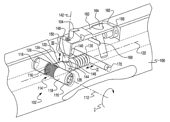
[0003] Machining tools such as multiple cartridge and/or insert tools for
boring,
milling and turning, generally have multiple cartridges each mounted onto the
tool
body by, for example a mounting screw. The alignment of the inserts is
important to
obtaining proper machining using these tools, which generally must position
multiple
inserts of the same tool body at the same time. Therefore, the inserts
typically have
both an adjustment associated with the seating location on the cartridge as
well as an
adjustment for the cartridge position itself, both axially and radially. The
cartridge
position adjustment also adjusts the position of the seated insert.
[0004] An example of a conventional fine adjustment of indexable inserts on,
for
example, a boring tool, uses a ground tapered pin 10, known as a Kam screw or
eccentric adjustment, to drive a push pin 20 up and deflect a member of the
tool,
usually a cartridge 30. The cartridge 30 sits in a cavity 40, with positioning
aided by a
key 50 or other locating device. A finish boring diameter is set by turning a
set screw
60 threaded into the cartridge 30 and contactirig the push pin 20 to create
preload by
deformation of the cartridge 30. The tapered pin 10 is seated in a ground hole
70 by a
threaded end 80 and has an adjusting surface 90 under the push pin 20. Insert
wear
-1-
CA 02668444 2009-05-04
WO 2008/057164 PCT/US2007/021738
adjustments are made by turning the tapered pin 10 to change the position of
the push
pin 20 toward or away from the cartridge 30. Fine adjustment is measured by
aligning
a mark on the tapered pin 10 with graduated marks on the body of the tool. The
tapered pin 10 is typically orientated to fall directly beneath the cutting
point making
precise location of all the features of the mechanism critical and difficult
to
manufacture.
SUMMARY
[0005] An adjustment system for positioning a cutting insert on a cutting tool
is
disclosed. In the disclosed adjustment system, an input motion produces a net
translation, e.g. of the cutting surface, that is less than the input motion.
In exemplary
embodiments, a fine net adjustment that is about 5 to 20% ( 10%),
alternatively
about 10% ( 10%), of the input motion is realized. In addition, physical
and/or
audible feedback to a user occurs during input motion. Exemplary embodiments
of
the adjustment system has a rotatable first rod with a surface having a
plurality of
flatted areas arranged radially, each at a different radial distance from an
axial center
of the first rod relative to a sequentially adjacent flatted area, a
translatable second rod
with an axially tapered surface, wherein a face of the first end of the second
rod
contacts one of the plurality of flatted areas, a biasing element positioned
to exert a
force to bias the face of the first end of the second rod to contact the
flatted area, and a
translatable push pin, wherein a face of the first end of the push pin
contacts the
tapered surface and wherein a face of the second end of the push pin
operatively
contacts a cartridge mounted on the cutting tool and in which the cutting
insert is
seated. A tool incorporating the adjustment system, a method of radially
positioning a
cutting surface of a cutting insert on a cutting tool, and a method of
adjusting a radial
position of a cutting surface of a cutting insert on a cutting tool are also
disclosed.
[0006] An exemplary adjustment system for positioning a cutting insert on a
cutting tool comprises a first rod rotatable about a first axis, the first
axis oriented in a
first direction, wherein the first rod includes a surface having a plurality
of flatted
areas arranged radially to the first axis and wherein each of the plurality of
flatted
-2-
CA 02668444 2009-05-04
WO 2008/057164 PCT/US2007/021738
areas is at a different radial distance from an axial center of the first rod
relative to a
sequentially adjacent flatted area, a second rod translatable along a second
axis
oriented in a second direction, wherein a first end of the second rod has a
face that
contacts one of the plurality of flatted areas and wherein a surface of the
second rod is
tapered in the axial direction, a biasing element positioned to exert a force
to bias the
face of the first end of the second rod to contact the one of the plurality of
flatted
areas, and a push pin translatable along a third axis oriented in a third
direction,
wherein a face of the first end of the push pin contacts the tapered surface
of the
second rod and wherein a face of the second end of the push pin operatively
contacts a
cartridge mounted on the cutting tool and in which the cutting insert is
seated.
[0007] An exemplary cutting tool comprises a tool body, a cartridge for one or
more cutting inserts, the cartridge mountable in a slot of the tool body with
a cutting
surface of the one or more cutting inserts projecting beyond a volume of the
tool body,
and an adjustment system for positioning the cutting insert in a radial
direction. The
adjustment system includes a first rod located in a first channel of the tool
body, the
first rod rotatable in the first channel about a first axis, the first axis
oriented in a first
direction, wherein the first rod includes a surface having a plurality of
flatted areas
arranged radially to the first axis and wherein each of the plurality of
flatted areas is at
a different radial distance from an axial center of the first rod relative to
a sequentially
adjacent flatted area, a second rod located in a second channel of the tool
body, a first
end of the second channel at least partially intersecting the first channel,
the second
rod translatable in the second channel along a second axis oriented in a
second
direction, wherein a first end of the second rod has a face that contacts one
of the
plurality of flatted areas and wherein a surface of the second rod is tapered
in the axial
direction, a biasing element located within the interior of the tool body to
exert a force
to bias the face of the first end of the second rod to contact the one of the
plurality of
flatted areas, and a push pin located in a third channel of the tool body, a
first end of
the third channel at least partially intersecting the second channel and a
second end of
the third channel at least partially intersecting the slot, the push pin
translatable in the
third channel along a third axis oriented in a third direction, wherein a face
of the first
-3-
CA 02668444 2009-05-04
WO 2008/057164 PCT/US2007/021738
end of the push pin contacts the tapered surface of the second rod and wherein
a face
of the second end of the push pin operatively contacts the mounted cartridge.
[0008] An exemplary method of radially positioning a cutting surface of a
cutting
insert on a cutting tool comprises adjusting an adjustment system for the
cutting
insert, wherein the adjustment system includes a first rod rotatable about a
first axis,
the first axis oriented in a first direction, wherein the first rod includes a
surface
having a plurality of flatted areas arranged radially to the first axis and
wherein each
of the plurality of flatted areas is at a different radial distance from an
axial center of
the first rod relative to a sequentially adjacent flatted area, a second rod
translatable
along a second axis oriented in a second direction, wherein a first end of the
second
rod has a face that contacts one of the plurality of flatted areas and wherein
a surface
of the second rod is tapered in the axial direction, a biasing element
positioned to
exert a force to bias the face of the first end of the second rod to contact
the one of the
plurality of flatted areas, and a push pin translatable along a third axis
oriented in a
third direction, wherein a face of the first end of the push pin contacts the
tapered
surface of the second rod and wherein a face of the second end of the push pin
operatively contacts a cartridge mounted on the cutting tool and in which the
cutting
insert is seated, and wherein adjusting the adjustment system changes the
flatted
surface contacting the face at the first end of the second rod.
[0009] Another exemplary method of adjusting a radial position of a cutting
surface of a cutting insert on a cutting tool comprises operating a first rod
to place one
of a plurality of flatted areas arranged radially to a first axis in contact
with a face at a
first end of a second rod, wherein the first rod is rotatable about the first
axis oriented
in a first direction, wherein the second rod is translatable along a second
axis oriented
in a second direction and wherein a surface of the second rod is tapered in
the axial
direction, and translating the second rod in the second direction to change a
portion of
the tapered surface contacting a face of a first end of a push pin,
translating the push
pin along a third axis oriented in a third direction, wherein a face of a
second end of
the push pin operatively contacts a cartridge mounted on the cutting tool and
in which
the cutting insert is seated.
-4-
CA 02668444 2009-05-04
WO 2008/057164 PCT/US2007/021738
[0010] It is to be understood that both the foregoing general description and
the
following detailed description are exemplary and explanatory and are intended
to
provide further explanation of the invention as claimed.
BRIEF DESCRIPTION OF THE DRAWING
[0011] The following detailed description can be read in connection with the
accompanying drawings in which like numerals designate like elements and in
which:
[0012] FIG. 1 shows a conventional arrangement for a prior art eccentric
adjustment system.
[0013] FIG. 2 is an isometric view of an exemplary embodiment of an adjustment
system for positioning a cutting insert on a cutting tool.
[0014] FIG. 3 shows a stepped height profile associated with the surface
having a
plurality of flatted areas.
[0015] FIG. 4 is a top axial cross-sectional view of an exemplary embodiment
of
an adjustment system for positioning a cutting insert on a cutting tool.
[0016] FIG. 5 is a side axial cross-sectional view of an exemplary embodiment
of
an adjustment system for positioning a cutting insert on a cutting tool.
[0017] FIG. 6 is a magnified view of the FIG. 5 showing the exemplary
embodiment of an adjustment system for positioning a cutting insert on a
cutting tool.
[0018] FIG. 7 is a cross-sectional radial view of an exemplary embodiment of
an
adjustment system.
DETAILED DESCRIPTION
[0019] An adjustment system for positioning a cutting insert on a cutting tool
has
a rotatable first rod with a surface having a plurality of flatted areas
arranged radially,
each at a different radial distance from an axial center of the first rod
relative to a
sequentially adjacent flatted area, a translatable second rod with an axially
tapered
surface, wherein a face of the first end of the second rod contacts one of the
plurality
of flatted areas, a biasing element positioned to exert a force to bias the
face of the
first end of the second rod to contact the flatted area, and a translatable
push pin,
-5-
CA 02668444 2009-05-04
WO 2008/057164 PCT/US2007/021738
wherein a face of the first end of the push pin contacts the tapered surface
and wherein
a face of the second end of the push pin operatively contacts a cartridge
mounted on
the cutting tool and in which the cutting insert is seated. A tool
incorporating the
adjustment system, a method of radially positioning a cutting surface of a
cutting
insert on a cutting tool, and a method of adjusting a radial position of a
cutting surface
of a cutting insert on a cutting tool are also disclosed
[0020] FIG. 2 is an isometric view of an exemplary embodiment 100 of an
adjustment system 102 for positioning a cutting insert 104 on a cutting tool
106. In
the FIG. 2 view, the adjustment system 102 is shown positioned within the
cutting
tool 106, which is shown in shadow to allow the internal arrangement of the
adjustment system 102 to be visible.
[0021] The adjustment system 102 comprises a first rod 110, a second rod 120,
a
biasing element 130, and a push pin 140. Additional features shown in FIG. 2
include
a cartridge 160 in which the cutting insert 104 is seated and a stop rod 170.
[0022] The first rod 110 is rotatable (1) about a first axis 112, which is
oriented in
a first direction. The first rod 110 includes a surface 114 having a plurality
of flatted
areas 116 arranged radially to the first axis 112. Each of the plurality of
flatted areas
116 is at a different radial distance from an axial center of the first rod I
10 relative to
a sequentially adjacent flatted area.
[0023] The second rod 120 is translatable (II) along a second axis 122
oriented in
a second direction. A first end 124 of the second rod 120 has a face 126 that
contacts
one of the plurality of flatted areas 116. The face 126 can optionally be
formed of a
hardened material to provide wear resistance to the face 126. An example of a
hardened material is cemented carbide, which may be incorporated in to the
second
rod 120 as an inserted surface or as ajoined surfaced, e.g., brazed or
soldered. A
surface 128 of the second rod 120 is tapered in the axial direction. That is,
the surface
128 of the second rod 120, or at least a portion thereof, is angled with
respect to the
second axis 122. Typically, the second axis is perpendicular or substantially
perpendicular ( 10 degrees) to the first axis 112, but other orientations can
also be
used. In operation, as the first rod 110 is rotated to place a different
flatted area 116 in
-6-
CA 02668444 2009-05-04
WO 2008/057164 PCT/US2007/021738
contact with the face 126 of the second rod 120, the second rod 120 translates
a
corresponding distance along the second axis 122.
[0024] The biasing element 130 is positioned to exert a force to bias the face
126
of the first end 124 of the second rod 120 to contact the one of the plurality
of flatted
areas 116. Examples of biasing elements include mechanical systems, such as
springs, dashpots, elastic materials, and non-mechanical systems, such as
compressible fluids and compressible gases. Biasing can be accomplished by any
desired technique. For example, a mechanical biasing element, such as the
spring
shown in FIG. 2, can be used. In exemplary embodiments, the biasing element is
preloaded to exert the force to bias the face of the first end of the second
rod to
contact the one of the plurality of flatted areas.
[0025] The push pin 140 is translatable (III) along a third axis 142 oriented
in a
third direction. A face 144 of the first end 146 of the push pin 140 contacts
the
tapered surface 128 of the second rod 120. Also, a face 148 of the second end
150 of
the push pin 140 operatively contacts the cartridge 160 mounted on the cutting
tool
106 and in which the cutting insert 104 is seated.
[0026] Additional elements can optionally be included with the adjustment
system
100 when the adjustment system is included in a cutting tool. For example, a
cartridge for one or more cutting inserts, such as a cartridge 160, can be
mounted in a
slot 162 of the tool body. The cartridge has one or more cutting inserts
mounted
thereon and the cartridge is mounted with cutting surfaces of the cutting
inserts
projecting beyond a volume of the tool body. The cartridge is mounted by any
suitable means, such as by the cap screw 164 depicted in FIG. 2. Further, the
cartridge includes an axial locating device, such as a locating screw 166,
which can be
adjusted to change an axial position of the cartridge in the slot 162.
[00271 The cartridge can be mounted to obtain a desired flexing of the
cartridge
under operation of the adjustment system. For example, in some embodiments,
the
cartridge includes a flex slot 168. The flex slot 168 is on a surface of the
cartridge
facing toward a surface of the slot 162. When the flex slot separates the
mounting
mechanism, such as the cap screw, from the point of contact of the adjustment
system,
-7-
CA 02668444 2009-05-04
WO 2008/057164 PCT/US2007/021738
such as the operative contact of the second end of the push pin with the
cartridge, and
the insert, then the cartridge flexes radially more easily at the end with the
insert.
[0028] The position of the insert relative to the flex slot, the mounting
mechanism, and the point of contact of the adjustment system provides
additional
variable that can be adjusted by a tool designer to influence the
adjustability of the
insert. For example, if the insert is axially located between the axial
position of the
cap screw and the axial position of the push pin, then the insert will
translate a radial
distance that is less than the translated distance of the push pin. Such a
translation can
be determined and considered. An example, is an axial position of the insert
that is at
a distance from the axial position of the cap screw that is 75% of the
separation
distance from the axial position of the cap screw to the axial position of the
push pin.
[0029] Further, the return force of the cartridge arising from the flexing
exerts a
reverse force through the push pin on the tapered surface to provide
additional bias for
the second pin to contact the flatted areas. This reverse force also provides
an
increased tactile feedback to the user rotating the first rod.
[0030] As previously noted, each of the plurality of flatted areas 116 is at a
different radial distance from an axial center of the first rod 110 relative
to a
sequentially adjacent flatted area. For example and for illustration purposes,
if the
surface profile of the surface 114 having a plurality of flatted areas 116 is
extended
linearly, as opposed to the peripheral arrangement about the first rod, then a
stepped
height profile 200, such as shown in FIG. 3, is observed. In the FIG. 3
representation,
the stepped height profile 200 includes sequential flatted areas 202, 202',
202", each
representing a desired height difference, e.g., a change in the radial
dimension.
Examples of height differences include 2 to 10 thousandths of an inch
(approximately
50-250 ^m), alternatively 2-4 thousandths of an inch (50-100 ^m). In the case
where
the sequentially flatted areas generally increase or decrease in height as the
peripheral
or linear position changes, a rotation, such as a counterclockwise rotation,
of the first
rod 110 toward 0 places a flatted area of reduced height 204 next to a
flatted area of
increased height 206, the difference in radial dimension larger than the
general
gradation in radial dimension between sequential flatted areas 202, 202',
202". In
-8-
CA 02668444 2009-05-04
WO 2008/057164 PCT/US2007/021738
such a case, the difference in radial dimension 208 forms a stop for the
rotatable first
rod. This stop can, in some embodiments, be correlated to a zeroing for the
adjustment system and can be used as a reference for adjustments. Although
FIG. 3
illustrates that each of the plurality of flatted areas is at a different
radial dimension
relative to a sequentially adjacent flatted area and that there is an
increasing/decreasing radial dimension as a function of peripheral position,
it will be
appreciated that other arrangements can be used, such as a stepped pyramid, an
alternating increasing/decreasing radial dimension, and a repeating sequence
of
changes in the radial dimension.
[00311 The flatted areas may extend the complete axial length of the first
rod, or a
portion of the axial extent. In the first rod 110 shown in FIG. 2, the
plurality of flatted
areas 116 extend over a centered portion of the axial extent with a portion of
larger
radial dimension 118 to both sides, e.g., the portions of larger radial
dimension
separate the flatted areas from each of the ends of the first rod or bound the
flatted
areas. However, the plurality of flatted areas can be at any portion of the
first rod and
are not restricted to either the center portion or to being bound by portions
of larger
radial dimension. Also, the radially arranged flatted areas, at least at a
portion
contacting the second rod, are each at a constant radial position along an
axial length
of the respective flatted surface.
[0032] FIG. 4 is a top, axial cross-sectional view of an exemplary embodiment
of
an adjustment system 300 for positioning a cutting insert on a cutting tool.
In the
embodiment shown in FIG. 4, the plurality of flatted areas 302 are bound on
either
side by a portion of larger radial dimension 304, 306. The biasing of the
second rod
308, by, for example, the biasing element 310, places a face 312 of the first
end 314 of
the second rod 308 in contact with the flatted areas 302. Further, because of
the
difference in radial dimension between the flatted areas 302 and the portions
on either
side 304, 306, the second rod also contributes to secure the first rod 316 in
its channel
318.
[0033] In addition, the ends 320, 322 of the first rod 316 and the transition
areas
between the radial dimension of the flatted areas 302 and the portions on
either side
-9-
CA 02668444 2009-05-04
WO 2008/057164 PCT/US2007/021738
304, 306 are chamfered or otherwise angled. The chamfering facilitates the
sliding of
surfaces of the first rod 316 past the face 312 of the second rod 308 during
installation, removal and/or replacement of the first rod 316.
[0034] An example of a method to replace the first rod 318 includes axially
aligning a replacement first rod with an installed first rod and applying
pressure on the
replacement first rod, such as by manual forces, mechanical forces, a hammer
and so
forth. Under the applied pressure, the installed first rod exits one end of
the channel.
The chamfers on both the installed first rod and replacement first rod
facilitated the
sliding of the surfaces past the face of the second rod during this process.
As the
replacement first rod is tapped into position, it clicks into place and is
held there by
the biasing force acting on the tapered pin. Once properly located, the
biasing of the
second rod into the flatted areas secures the replacement rod in place in the
channel.
[0035] Additional features associated with exemplary embodiments of the
adjustment system are illustrated in FIG. 4. For example, the tapered surfaces
330 of
the second rod 308 are shown. In another example, the positioning of the
biasing
element 310, in the form of a spring, coaxially about a second end 332 of the
second
rod 308 is shown. A first end of the spring contacts a stop 334 on the second
rod 308
and a second end of the spring contacts the stop rod 336. The second end 332
can be
spaced away from the surface of the stop rod 336 or, the second end 332 of the
second
rod 308 can contact a surface of the stop rod 336. Separation between the
second end
332 and the surface of the stop rod 336 provides space for translation of the
second
rod 308 during operation of the adjustment system. The biasing element 310
contributes to maintaining the separation distance by biasing the face 312 of
the
second rod 308 toward the flatted areas 302. The stop rod 336 is optional and
can be
replaced by any feature that provides a surface for the biasing element,
although a stop
rod contributes to ease of manufacture and replacement. In further example, an
interface 338, such as a hex head, can be included with the first rod 316 for
rotating
the first rod 316.
[0036] The channels in the tool body 340 for some of the components of the
adjustment system are also seen in FIG. 4. The channel 318 of the first rod
316 is
-10-
CA 02668444 2009-05-04
WO 2008/057164 PCT/US2007/021738
arranged substantially ( 10 ) perpendicular to the channel 342 for the second
rod
308. The channel 344 for the stop rod 336 is arranged substantially ( 10 )
perpendicular to the channe1342 for the second rod 308. The channel 342 for
the
second rod 308 has a first end that at least partially intersects the channel
318 for the
first rod 316 and has a second end that at least partially intersects the
channel 344 for
the stop rod 336. Various manufacturing techniques can be used to form the
channels.
In one example and for ease of manufacture and assembly, the channel 342 for
the
second rod 308 can run the axial length of the tool body 340 and can be formed
by
drilling, albeit with a suitable finish to allow movement of the parts of the
adjustment
system. The other channels can be drilled or reamed. In the case of the first
rod 316,
the operation with the second rod 308 maintains the first rod's position in
the tool
body. In the case of the stop rod 336, the stop rod can be pressed fit or can
be a
knurled pin.
[0037] The channels are advantageously located dispersed in the tool body. For
example, the channel for the first rod is axially offset from the location of
the
cartridge and the slot. This results in less bending of the tool, stronger
cross-sections,
reduced cracking of the tool body and overall increased tool life. This is at
least
partially due to the multiple channels and slot not being in the same cross-
section. In
addition, the channels can be circular in cross-section, or substantially
circular,
thereby reducing stresses that can occur from squared geometries. Further, the
channels can be positioned sufficiently close about a neutral axis of bending
of the
machining tool so as to maximize the resistance to bending. For example, the
channel
of the second rod is at a location of neutral compressive or tensile stresses.
Similarly,
cross-channels such as the channels for the first rod, for the stop rod and
for the push
pin, are at a location of neutral compressive or tensile stresses created by
the cutting
forces.
[0038] FIG. 5 is a side axial cross-sectional view of an exemplary embodiment
of
an adjustment system for positioning a cutting insert on a cutting tool. In
general, the
FIG. 5 view illustrates the arrangement of the adjustment system 400 in the
tool body
402 and its relationship to the cartridge 404 for the cutting insert 406 and
the stop rod
- ri -
CA 02668444 2009-05-04
WO 2008/057164 PCT/US2007/021738
408. The adjustment system 400 includes the first rod 410 with the flatted
areas 412,
the second rod 414, the biasing element 416 for the second rod 414 and the
push pin
418 in contact with the tapered surface 420 and operatively contacting the
cartridge
404. Also illustrated are the flex slot 422, the mounting screw 424 and the
locating
screw 426 for the cartridge 404.
[0039] FIG. 6 is a magnified view of the FIG. 5 showing the exemplary
embodiment of an adjustment system 500 for positioning a cutting insert on a
cutting
tool. .In the FIG. 6 view, the tapered surfaces 502 of the second rod 504 and
the
contact between the tapered surfaces 502 and the push pin 506 are more clearly
shown. For example, the face 508 of the first end 510 of the push pin 506 has
an
angled surface that correlates to the tapered surface 502 of the second rod
504. As the
second rod 504 translates (T1), the face 508 maintains line contact with an
axially
extending length of the tapered surface 502 of the second rod 504 and the push
pin
506 translates (T2). The second end 512 of the push pin 506 operatively
contacts the
cartridge 514, either directly or, as shown in FIG. 6, through an intermediate
structure
such as a contact pin 516.
[0040] In the FIG. 6 view, the contact between the second rod 504 and the
flatted
areas 518 of the first rod 520 are also more clearly shown. For example, the
flatted
areas 518 are rotatable (RI) to variously contact the face 522 of the second
rod 504,
which can be a hardened material 524. The flatted areas 518 have differing
radial
dimension and, as previously discussed in reference to FIG. 3, produce a stop
526. In
operation, rotation (Rl) of the first rod changes the flatted area contacting
the face 522
of the second rod and translate (Tl) the second rod; translation of the
tapered surfaces
502 causes translation (T2) of the push pin 506 and movement (MI) of the
cartridge
514 and the cutting insert 526. An example of the translation of the push pin
(T2) is
gradations of 2 to 4 microns and to a maximum distance of about 80 microns.
[0041] FIG. 7 is a cross-sectional radial view of an exemplary embodiment of
an
adjustment system. In the FIG. 7 view, the contact between the second rod 602
and
the push pin 604 is illustrated. In radial cross-section of the cutting tool,
the push pin
604 is not tapered, but rather is square and horizontal, making tangential
contact 606
-12-
CA 02668444 2009-05-04
WO 2008/057164 PCT/US2007/021738
io a radially extending periphery 608 of the tapered surface of the second rod
602. A
tangential contact as seen in FIG. 7 allows for less precision in the
machining of the
channels for the push pin and the second rod.
[0042] As described herein, the second rod has a tapered surface that
translates a
distance correlated to the change in height of the flatted areas as the first
rod is
rotated, and by which the push pin translates and operates to change the
radial position
of the cutting insert. The tapered surface reduces the amount of adjustment
provided
by manipulation of the flatted areas alone, allowing for very fine adjustment
of the
cutting surfaces of the cutting insert. The amount of change to the radial
position of
the cutting insert as a result of the tapered surface can be calculated and/or
calibrated
to the amount of rotation of the first rod. For example, the following formula
applies:
R = xtan(8)
where x is the change in height of the flatted areas and 0 is the angle of the
tapered
surface (refer to FIG. 6 for an illustration of angle 0).
[0043] The location of the insert relative to the cap screw that mounts the
cartridge and the operative contact point of the push pin on the cartridge
also provides
an additional fine adjustment of the cutting surfaces over manipulation of the
flatted
areas alone. Adding this refinement in adjustment to the above equation, one
can
develop the following relationship:
R = x tan(8) x (ratio, )
where x is the change in height of the flatted areas, 0 is the angle of the
tapered
surface, and ratio1 is the ratio of the axial distance of the insert from the
cap screw to
the axial distance of the contact point from the mounting point. the distance
from the
axial position of the set crew to the axial position of the center of the
cutting surfaces
of the cutting insert (AB in FIG. 5) to the distance from the axial position
of the cap
screw to the axial position of the center of the push pin (AC in FIG. 5).
Thus:
-13-
CA 02668444 2009-05-04
WO 2008/057164 PCT/US2007/021738
R= x tan(B) x AB
AC
[0044] The adjustment system adjusts linearly. A fixed rotation of the input,
at
any point in the operational range of the system, produces the same final net
translation. For example, a rotation of X will have the same final net
translation of Y
^m. In contrast, eccentric systems operate non-linearly.
[0045] Examples of lengths and operating distances of exemplary embodiments
include: (a) the push pin translatable along the third axis in gradations of 2
to 6
microns and to a maximum distance of about 80 microns; (b) the height
difference or
change in radial dimension between successive flatted areas of I to 5
thousandths of
an inch (approximately 25-125 ^m), alternatively 2-4 thousandths of an inch
(50-100
Dm); and (c) the tapered surface of the second rod at an angle of 5 to 15
degrees to the
second axis, alternatively 9-12 degrees, alternatively about 11 degrees.
[0046] The adjustment system disclosed herein can be used to radially position
a
cutting surface of a cutting insert on a cutting tool. For example, an
exemplary
method of radially positioning a cutting surface of a cutting insert on a
cutting tool
comprises adjusting an adjustment system for the cutting insert, wherein the
adjustment system includes a first rod rotatable about a first axis, the first
axis
oriented in a first direction, wherein the first rod includes a surface having
a plurality
of flatted areas arranged radially to the first axis and wherein each of the
plurality of
flatted areas is at a different radial distance from an axial center of the
first rod
relative to a sequentially adjacent flatted area, a second rod translatable
along a second
axis oriented in a second direction, wherein a first end of the second rod has
a face
that contacts one of the plurality of flatted areas and wherein a surface of
the second
rod is tapered in the axial direction, a biasing element positioned to exert a
force to
bias the face of the first end of the second rod to contact the one of the
plurality of
flatted areas, and a push pin translatable along a third axis oriented in a
third direction,
-14-
CA 02668444 2009-05-04
WO 2008/057164 PCT/US2007/021738
wherein a face of the first end of the push pin contacts the tapered surface
of the
second rod and wherein a face of the second end of the push pin operatively
contacts a
cartridge mounted on the cutting tool and in which the cutting insert is
seated.
Adjusting the adjustment system changes the flatted surface contacting the
face at the
first end of the second rod. Further, adjusting the adjustment system changes
the
portion of the tapered surface of the second rod which contacts the push pin.
The
result of the push pin translation is the radial translation of the cartridge
and
associated cutting surfaces of the cutting insert mounted therein.
[0047] Another exemplary method of adjusting a radial position of a cutting
surface of a cutting insert on a cutting tool comprises operating a first rod
to place one
of a plurality of flatted areas arranged radially to a first axis in contact
with a face at a
first end of a second rod, wherein the first rod is rotatable about the first
axis oriented
in a first direction, wherein the second rod is translatable along a second
axis oriented
in a second direction and wherein a surface of the second rod is tapered in
the axial
direction, and translating the second rod in the second direction to change a
portion of
the tapered surface contacting a face of a first end of a push pin. As the
portion of the
tapered surface contacting a face of a first end of a push pin changes, the
push pin
translates along a third axis oriented in a third direction. The face of a
second end of
the push pin then operatively contacts a cartridge mounted on the cutting tool
and in
which the cutting insert is seated. In some embodiments, translating the push
pin
along the third axis flexes the cartridge. Further, the method optionally
biases the
second pin to contact the face at the first end to the flatted areas.
[0048] Exemplary embodiments of the disclosed adjustment system and method
of adjusting provide a feedback to an operator indicating adjustment of the
radial
position of the cutting surface. For example, the feedback can be correlated
to each
change of the flatted area. As the flatted area in contact with the second rod
changes,
the biasing forces of the adjustment system, both from the biasing element and
translated through the push pin, are available to the user through tactile
senses. Also,
the ratcheting or clicking of the face of the second rod contacting the
changing flatted
areas are available to the user through audible senses. Either or both of
these feedback
mechanisms can be used.
- t5-
CA 02668444 2009-05-04
WO 2008/057164 PCT/US2007/021738
[0049] No gauges are necessary. Advantageously, it is not necessary to read a
graduated surface to determine adjustment where light may not be good, reach
into a
machining tool may be limited, or graduated surfaces can be dirty. Operators
can
make very fine adjustments with a normal shop tool.
[0050] The method of manufacturing is simplified, making the product more cost
effective. Also, the wear parts, such as the first rod with the flatted areas,
can be
replaced without disassembling the tool.
[0051] Although described in connection with preferred embodiments thereof, it
will be appreciated by those skilled in the art that additions, deletions,
modifications,
and substitutions not specifically described may be made without departure
from the
spirit and scope of the invention as defined in the appended claims.
-16-