Note: Descriptions are shown in the official language in which they were submitted.
CA 02668532 2009-06-09
1
Bower.
The present invention concerns a bower.
In particular, the invention is meant for a bower which can
be erected in a detached manner as a garden or swimming
pool bower.
Traditionally, such a bower offers many application
possibilities. It may be used for example as an awning, a
marquee, as a protection from the rain, a changing cubicle,
a summer house, a flower shop, a smoking space, a showroom,
a reception room, a workshop, a dinette, a storage room, an
emergency accommodation and the like. It may also be used
to cover a Jacuzzi, swimming pool or plunge pool arranged
in a garden or on an outdoor terrace.
Traditionally, little garden and swimming pool bowers are
made of a wooden or metal frame with standing posts, cross
connections and a roof structure, onto which can be fixed
one or several fixed or removable side walls and a covering
roof, which are either or not erected permanently.
Said side walls and the roof can seal the frame entirely or
partly from the outside, such that a space in the shape of
a tent or a chapel is formed on the inside which may offer
protection from sunlight, rain and other unfavorable
weather conditions, and such that some privacy can also be
guaranteed.
CA 02668532 2009-06-09
2
A known disadvantage of these conventional systems is that
they are usually heavy and complex.
As a result, they are rather expensive as far as
construction, storage, transport, purchase and maintenance
are concerned, and they are moreover difficult to install
for do-it-yourselfers.
An additional disadvantage is that, when the bower has to
be pulled down again, this requires a lot of effort, and it
moreover needs a lot of storage space.
A disadvantage related thereto is that people usually
refrain from pulling the bower down, such that it remains
erected in the garden all summer long, as a result of which
it is exposed to wind and rain during this whole period,
such that the bower will rather quickly look weather-
beaten.
Another disadvantage of a permanent erection of the bower
is that it may be seriously damaged in case of windy
weather, as well as its environment.
A further known disadvantage is that bowers often obstruct
the view as they are usually erected more or less
permanently, and their side walls or roofs cannot be easily
moved or taken away after use.
The latter, when they are made of canvass, are moreover
difficult to tighten smoothly, leading to pouches or
CA 02668532 2009-06-09
3
fluttering, especially in case of windy or rainy weather,
which may be annoying and may lead to further damage.
Also, the present invention aims to remedy the above-
mentioned and other disadvantages by providing a bower
which is mainly formed of a frame of at least four posts,
connected in pairs by means of joists extending in the
longitudinal direction, and which are moreover connected in
pairs by means of two trusses which are each formed of
slanting joists which are connected at their far ends so as
to form an angle, whereby the truss is provided over a part
of the width of a roof frame under which are provided two
rollers extending in the longitudinal direction of the
bower and on which is wound a cloth which can be laterally
unwound over the remaining width of the truss and which can
be further guided down over a return pulley at the top end
of the posts up to the foot of the posts.
A major advantage thereof is that the construction can be
kept very simple and that, consequently, a bower according
to the invention can be manufactured, stored, offered,
transported and installed at a favorable price. The
installation does not necessarily require any action of a
craftsman.
Another advantage of this simple construction is that the
bower occupies very little space and can be manually
operated. As a result, one does not depend on power supply
among others, resulting in less breakdowns and at the same
time saving energy, which is environment-friendly.
CA 02668532 2009-06-09
4
Another advantage is that the cloth can be unrolled
whenever one wishes to use the bower, and that it can be
rolled up again after use, such that it is protected from
dirt and damage and as a result will last longer.
A further additional advantage is that, by rolling up the
cloths when the bower is not in use, also the visible
hinder which it might cause is restricted to a minimum,
since only the thin and simple supporting structure, which
is an essential characteristic thereof, can stay more or
less permanently erected.
Yet another advantage consists in that, thanks to the light
and self-supporting structure of a bower according to the
invention, it no longer needs to be fixed to an outer wall
or any other type of fixed support, or at least to a lesser
extent.
In a preferred embodiment is provided at least one cabinet
connecting two opposite posts on the crosscut end of the
bower, and which is provided with a longitudinal slot. In
this cabinet, i.e. in the longitudinal direction of the
cabinet, is provided a roller on which is wound a cloth
which can be drawn up along the posts via the aforesaid
slot, up against the bottom side of the roof frame.
An advantage thereof is that not only the side walls can be
easily rolled up and unrolled, but that also the front side
and/or rear side of the bower can be easily unrolled and
rolled up again in this way.
CA 02668532 2009-06-09
Said roller or rollers are further provided with a spring
which is clamped while the cloth concerned is being
unrolled so as to wind up said cloth again when the latter
is released under the influence of the built-up spring
5 tension.
Thanks to said spring tension, and partly as the cloth
being rolled up on rollers and being guided over a return
pulley makes it possible to keep said cloth well taut over
its entire width, pouches or fluttering can be prevented,
especially in case of windy or rainy weather, which may not
only be annoying but which may also lead to damage or a
shorter life.
Storage is done automatically when the side walls and/or
the roof are/is rolled up since, when the cloths are rolled
up, well protected against dirt and damage, and not
obstructing the view in any way whatsoever, they are stored
in the cabinets provided to that end.
In order to keep the cloths open when unwound, a lock is
further provided.
This may be formed of simple hooks behind which the unwound
cloth can be hooked, or it may be based on a reel system.
In another preferred embodiment, the roof frame is provided
with a bottom extending in the longitudinal direction up to
a distance from the roof frame and thus forming a gap
through which the cloth can be unwound.
CA 02668532 2009-06-09
6
The cloth is then provided with a lath on its free end
whose cross section is larger than the opening formed by
the gap.
In order to be able to easily unwind the cloth, a rope or
ribbon is provided on the above-mentioned lath which is
externally guided over a return pulley and is pulled
through up to a comfortable upward reach.
In another preferred embodiment, the posts and joists are
formed of L-shaped struts whose legs are directed outward
so as to cover the side edges of the unrolled cloth.
The advantages thereof are that, between cloth and frame,
in an unrolled condition, there are no more air gaps which
might lead to draughts or pouches being formed in the
cloth, and which might thus be annoying or could lead to
damage, especially in case of bad weather conditions.
In yet another preferred embodiment, the free end of the
cloth which is being pulled up has the shape of the lower
side of the truss as a whole and the roof frame, and it is
in particular made trapezoidal.
An advantage thereof is that the pulled-up cloth can be
tightly fit to the shape of the roof, of the roof frame
respectively, which has the same positive effect as
obtained with the L-shaped struts as mentioned above.
In another preferred embodiment, elements are provided in
the roof frame which make it possible to apply lamps,
CA 02668532 2009-06-09
7
decoration, acoustic installation components, cooling or
heating elements, insect traps, alarm systems or the like.
An advantage thereof is that the bower can be adapted in a
simple and easy way to different conditions of use
requiring or needing a strongly varying, adapted or
atmospheric setting.
In order to better explain the characteristics of the
invention, the following preferred embodiment of a bower
according to the invention is described by way of example
only, without being limitative in any way, with reference
to the accompanying drawings, in which:
figure 1 schematically represents a bower according to
the invention, seen in perspective;
figure 2 represents a cross section according to line
II-II in figure 1;
figure 3 is a magnification of the part of the roof
indicated with F3 in figure 2;
figure 4 is an exploded view of a torsion shaft with
which the cloths can be rolled up;
figure 5 is a section of a cabinet in which a rolled-up
cloth is stored according to arrow V-V in figure 1;
figure 6 schematically represents the bower with a half
drawn-up back wall, seen in perspective;
figure 7 shows a detail of an angle of the bower
indicated by F7 in figure 6.
CA 02668532 2009-06-09
8
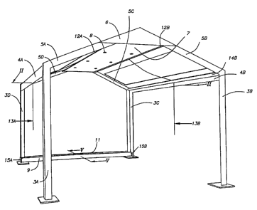
Figures 1 to 5 schematically represent a bower 1 that is
not in use, i.e. with the cloths forming the side walls
and/or the roof being rolled up and safely stored away.
The bower is hereby built of a metal frame, formed of four
vertical posts 3A-3D, connected in pairs by the joists 4A
and 4B, and of a roof formed of two trusses built of the
slanting joists 5A-5D respectively, and of a roof frame 6.
The roof frame 6 is provided with a bottom 7 in which has
been provided atmospheric lighting in the form of lamps 8.
The posts 3A-3D and the joists 5A-5D are formed of L-shaped
struts whose legs are directed outward.
Between the two rear posts 3D and 3C, a cabinet 9 is
provided at ground level in which the cloth is put which is
to form the rear wall, and which is represented in figure 5
as being rolled-up and stored away.
Above the bottom 7 of the roof frame 6 are situated two
parallel rollers 10A and 10B on which the cloths are wound
which are to form the roof and the side walls.
These cloths are provided with a lath on their free ends.
In the case of the cloth which is to form the rear wall,
said lath 11 has a width corresponding to that of the
bottom 7 of the roof frame 6.
CA 02668532 2009-06-09
9
In the case of the cloths which are to form the roof, the
respective laths 12A and 12B essentially have the same
widths as those of the roof and the side wall.
In the middle of the laths 12A and 12B is provided a rope
or a ribbon 13A, 13B respectively which is guided down
externally over a return pulley 14A, 14B respectively, up
to a comfortable upward reach.
At the foot of the posts 3A-3D are provided hooks 15A-15D
on the inside which can co-operate in pairs and behind
which the laths 12A and 12B can be hooked at ground level.
Figure 4 shows an example of a traditional roller as is
applied in the roof frame or in the cabinet 9 and whose
construction and finish is well known to the craftsman.
This figure shows how the roller 7 or 10 is provided with a
shaft 16, around which is provided a torsion spring and
which is fixed to the shaft 16 with one far end and to the
roller 10 with the other far end.
The shaft 16 is fixed with both far ends to the roof frame
6, the cabinet 9 respectively.
On each roller is wound a cloth which is fixed on the
roller 10A-10C with one edge.
It should be noted that the cross section of the lath 11 is
considerably larger than the slot 17 formed by the walls of
the cabinet 9 over its entire length and through which the
cloth in the cabinet 9 is guided to the roller 10C.
CA 02668532 2009-06-09
Figure 6 schematically represents the bower when it is
ready for use, seen in perspective, i.e. with the cloths
forming the roof and the side walls unrolled and hooked,
5 and with the cloth forming the rear wall only partly drawn
up for clarity's sake.
Figure 7 shows a detail of the part indicated by F7 in
figure 6.
The use of the bower 1 and the operation of the cloths is
very simple and as follows.
Starting from the situation as shown in figures 1 to 5,
which represent a situation which is not ready for use, the
cloth which is to form the rear wall and which is stored in
the cabinet 9 is drawn up against the bottom 7 of the roof
frame 6 by means of the lath 11. Thanks to its trapezoidal
shape, it fits up tightly and without any gaps being formed
on the frame forming the rear wall.
As a result of the cloth being unrolled, the torsion spring
16 situated in the cabinet 9 is clamped. The cloth being
hooked with the lath 11 on hooks which are provided to that
end on the bottom side of the bottom 7 of the roof frame 6,
together with the downward directed tensile force of the
clamped spring 16 make sure that the cloth is stretched
between the frame without any pouches being formed or
without any fluttering.
CA 02668532 2009-06-09
11
In a similar way, by pulling the rope or the ribbon 13A or
13B, the cloth which is wound around a longitudinally
directed roller 10A or 10B on the bottom 7 of the roof
frame 6 will be unrolled and guided externally along with
said rope or ribbon over the return pulleys 14A, 14B
respectively, up to the bottom level, where it is hooked
around the hooks 15A, 15B provided to that end with the
laths 12A and 12B respectively.
During the unrolling, the spring 16 situated in the rollers
10A and 10B will be clamped on the bottom 7 of the roof
frame 6, so that, analogously to what happened in the rear
wall, the tensile force of the spring 16, which is directed
upward this time, will make sure that the cloth remains
evenly stretched between the frame without any pouches
being formed.
In this way is obtained a bower which is ready for use, as
represented in figure 6, but in which, for clarity's sake,
the cloth of the rear wall is only partly drawn up.
If the bower is no longer of use, one only has to unhook
the cloths which are hooked behind their respective hooks
15A and 15B by means of the laths 11, 12A and 12B, after
which, as a result of the tensile force of the springs
which had been built up due to the unrolling, said cloths
will be rolled up again in their respective cabinet 9 or
storage room above the bottom 7 of the roof frame 6.
The present invention is by no means restricted to the
embodiments described by way of example and represented in
CA 02668532 2009-06-09
12
the accompanying drawings; on the contrary, such a bower
according to the invention can be made in all sorts of
shapes and dimensions while still remaining within the
scope of the invention.