Note: Descriptions are shown in the official language in which they were submitted.
CA 02668667 2015-05-25
REALISTIC VIDEO REELS
FIELD OF THE INVENTION
[0001] This invention relates to gaming machines.
[0002] In particular, embodiments described herein relate to video
data, for output on
a gaming machine, that simulates a realistic visual attributes of a
mechanically driven reel slot
machine.
BACKGROUND
[0003] As technology in the gaming industry progresses, the
traditional mechanically
driven reel slot machines are being replaced by electronic machines having an
LCD video
display or the like. Processor-based gaming machines are becoming the norm.
One reason for
their increased popularity is the nearly endless variety of games that can be
implemented
using processor-based technology. The processor-based gaming machines permit
the
operation of more complex games, incorporate player tracking, improve
security, permit
wireless communications, and add a host of digital features that are not
possible on
mechanical-driven gaming machines. The increasing cost of designing,
manufacturing, and
maintaining complex mechanical gaming machines has also motivated casinos and
the gaming
industry to abandon these older machines.
OVERVIEW
[0004] Illustrative embodiments provide a gaming machine configured
to output video
data that simulates mechanical reels in a traditional mechanical slot machine.
Embodiments
detailed herein contribute to the emulation and perception of a
mechanical machine by providing video data adaptations that each simulate a
realistic visual
attribute of a mechanical reel gaming machine.
[0005] One illustrative embodiment relates to a gaming machine. The
gaming machine
includes a first video display device, a second video display device, and a
cabinet defining an
interior region of the gaming machine. The cabinet is adapted to house a
plurality of gaming
machine components within or about the interior region. The first video
display device is
disposed within or about the interior region, is configured to output a visual
image in response
1
CA 02668667 2015-05-25
to a control signal, and includes one or more controllably transparent
portions. The second
video display device is arranged relative to the first video display device
such that a common
line of sight passes through a portion of the first video display device to a
portion of the
second video display device. The gaming machine also includes at least one
processor
configured to execute instructions, from memory, that: a) display video data
for multiple
video reels on the second video display device, wherein the video data for
each of the multiple
video reels depicts a reel strip with multiple reel game symbols; b) permit
game play of a reel
game of chance that uses the multiple video reels displayed by the second
video display
device, and c) display video data, on the second video display device, that
includes a video
data adaptation to the video data for the multiple video reels, wherein the
video data
adaptation simulates a realistic visual attribute of a real mechanical reel in
a gaming machine.
[0006] Another illustrative embodiment relates to a method of
providing a game of
chance on a gaming machine. The method includes displaying the game of chance
using a
first video display device and/or a second video display device included in
the gaming
machine. The second video display device is arranged relative to the first
video display device
such that a common line of sight passes through a video window portion of the
first video
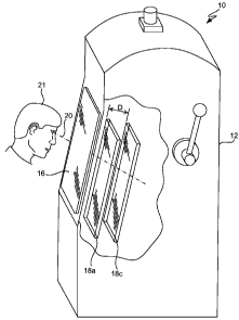
display device to a video reel portion of the second video display device. The
game of chance
includes multiple video reels displayed on the second video display device and
each video reel
includes multiple video symbols on a video reel strip. The method also
includes, during the
game, simulating the movement of symbols on each video reel in the multiple
video reels on
the second video display device. The method further includes for one or more
of the video
reels in the set of video reels, displaying a video data adaptation to video
data for one or more
of the multiple video reels, wherein the video data adaptation simulates a
realistic visual
attribute of a real mechanical reel in a gaming machine.
[0007] Another illustrative embodiment relates to logic encoded in one or
more
tangible media for execution and, when executed, operable to provide a game of
chance on a
gaming machine.
[0007a] In another illustrative embodiment, a gaming machine includes
a cabinet
defining an interior region of the gaming machine, the cabinet adapted to
house a plurality of
gaming machine components. The gaming machine further includes a first video
display
device supported by the cabinet and configured to output a visual image in
response to a
control signal. The first video display device includes one or more
controllably transparent
2
CA 02668667 2015-05-25
portions. The gaming machine further includes a second video display device
supported by
the cabinet arranged relative to the first video display device such that a
common line of sight
passes through a portion of the first video display device to a portion of the
second video
display device, and at least one processor. The at least one processor is
configured to execute
instructions stored on a memory to cause a display of video data for multiple
video reels by
the second video display device, wherein the video data for each of the
multiple video reels
depicts a video reel strip with multiple reel game symbols. The at least one
processor is
further configured to enable game play of a reel game of chance using the
multiple video reels
displayed by the second video display device, and to control display of the
video data, by the
second video display device, to include a video data adaptation to the video
data, wherein the
video data adaptation provides a simulated three dimensional effect to one of
the video reels
from the multiple video reels. The simulated three dimensional effect provides
an outward
bow and curvature to a reel game symbol on the video reel when the reel game
symbol is
displayed in a central symbol display portion such that the reel game symbol
is wider when
displayed in the central symbol display portion than when the reel game symbol
is displayed
in at least one of a top symbol display portion and a bottom symbol display
portion.
[000713] In another illustrative embodiment, a method of providing a
game of chance on
a gaming machine includes causing video data corresponding to the game of
chance to be
displayed on a second video display device, the video data including multiple
video reels
where each of the multiple video reels depicts a video reel strip with
multiple reel game
symbols. The second video display device is arranged relative to a first video
display device
such that a common line of sight passes through a portion of the first video
display device to a
portion of the second video display device. The method further includes
enabling game play
of the game of chance by simulating movement of each video reel in the
multiple video reels
on the second video display device, and controlling display of the video data
by the second
video display device to include a video data adaptation to the video data. The
video data
adaptation provides a simulated three dimensional effect to one of the video
reels from the
multiple video reels. The simulated three dimensional effect provides an
outward bow and
curvature to a reel game symbol on the video reel when the reel game symbol is
displayed in a
central symbol display portion such that the reel game symbol is wider when
displayed in the
central symbol display portion than when the reel game symbol is displayed in
at least one of
a top symbol display portion and a bottom symbol display portion.
3
CA 02668667 2015-05-25
[0007c] In another illustrative embodiment, a computer-readable medium
stores
executable instructions to direct a processor of a gaming machine to perform a
method
including causing video data corresponding to the game of chance to be
displayed on a second
video display device. The video data includes multiple video reels where each
of the multiple
video reels depicts a video reel strip with multiple reel game symbols. The
second video
display device is arranged relative to a first video display device such that
a common line of
sight passes through a portion of the first video display device to a portion
of the second video
display device. The method further includes enabling game play of the game of
chance by
simulating movement of each video reel in the multiple video reels on the
second video
display device, and controlling display of the video data by the second video
display device to
include a video data adaptation to the video data. The video data adaptation
provides a
simulated three dimensional effect to one of the video reels from the multiple
video reels. The
simulated three dimensional effect provides an outward bow and curvature to a
reel game
symbol on the video reel when the video game symbol is displayed in a central
symbol
display portion such that the reel game symbol is wider when displayed in the
central symbol
display portion than when the reel game symbol is displayed in at least one of
a top symbol
display portion and a bottom symbol display portion.
[0007d] In another illustrative embodiment, a computer-readable medium
stores
executable instructions which, when executed by a processor of a gaming
machine, cause any
one or more of the methods described herein to be carried out.
100081 These and other features and advantages of illustrative
embodiments will be
described in more detail below with reference to the associated figures.
BRIEF DESCRIPTION OF THE DRAWINGS
[0009] Figure lA shows a simple depiction of perspective viewing of a
gaming
machine with mechanical reels.
[0010] Figure 1B shows a simple depiction of changing position in
front of a video
reel gaming machine with windows on a front panel and the effect of changing
position on
visibility of a rear display device.
[0011] Figure 1C shows a simple depiction of perspective for curved
mechanical reels
when viewing from in front of a mechanical reel gaming machine.
3A
CA 02668667 2015-05-25
[0012] Figure 1D shows a fore-lighting technique used in some
mechanical reel
gaming machines with opaque reel strips.
[0013] Figure 2A shows video output on layered displays and
configured to
realistically simulate mechanical reels in accordance with one embodiment.
[0014] Figure 2B shows the video output of Figure 5A separated into front
and back
video for display on front and back displays, respectively, in accordance with
one
embodiment.
[0015] Figure 2C illustrates the video data output on rear display
device of Figure 2B
in greater detail in accordance with a specific embodiment.
[0016] Figure 3A shows a video reel strip with slight curvature on its
lateral sides in
accordance with one embodiment.
3B
CA 02668667 2009-05-05
WO 2008/063956
PCT/US2007/084429
[0017] Figure 3B shows a graphical simplification of perspective video
adaptations applied to reel symbols sides in accordance with one embodiment.
[0018] Figure 3C shows a simplified version of simulated preferential
lighting of
a reel strip in accordance with one embodiment.
[0019] Figure 3D shows a simplified version of simulated back-lighting for
reel
strip in accordance with one embodiment.
[0020] Figure 4A shows layered displays in a gaming machine in
accordance with
one embodiment.
[0021] Figure 4B shows layered displays in a gaming machine in
accordance with
another embodiment.
[0022] Figure 4C shows another layered video display device arrangement
in
accordance with a specific embodiment.
[0023] Figures 5A and 5B illustrate a gaming machine in accordance with
a
specific embodiment.
[0024] Figure 6 illustrates a control configuration for use in a gaming
machine in
accordance with another specific embodiment.
DESCRIPTION OF THE PREFERRED EMBODIMENTS
[0025] The present invention will now be described in detail with
reference to a
few preferred embodiments thereof as illustrated in the accompanying drawings.
In
the following description, numerous specific details are set forth in order to
provide a
thorough understanding of the present invention. It will be apparent, however,
to one
skilled in the art, that the present invention may be practiced without some
or all of
these specific details. In other instances, well known process steps and/or
structures
have not been described in detail in order to not unnecessarily obscure the
present
invention.
[0026] Gaming machine manufacturers highly regard customer preference
information. When the assignee introduced CRT-based slot machines in 1975, the
reaction of some players was less than enthusiastic. The CRT screens jolted
players
4
CA 02668667 2009-05-05
WO 2008/063956
PCT/US2007/084429
from a gaming activity based on a complex mechanical apparatus to a single,
flat,
video screen. The technology of 1975 pales in comparison to that of today. And
yet,
amongst casino patrons and other players, the perceived value of mechanically
driven
reel slot machines remains high.
[0027] Customer preference information belonging to the assignee shows that
players trust the old mechanical machines. Some players feel that a lack of
mechanically driven reels causes a slot game to be cheapened - and somehow
less
random. Many players believe that it is impossible to externally tamper with
or (to
player detriment) control outcomes for a mechanically driven machine. These
people
also commonly believe that manipulating outcomes portrayed on a video screen
is
both easily accomplished and undetectable to a player. Others simply prefer
the feel
and appearance of an electromechanical apparatus as they pull a handle, hear
and feel
solenoid and latches as they engage and disengage, and watch as spinning reels
click
into position to display an outcome. A loyal base of players still favors the
traditional
mechanical stepper machines, even today.
[0028] The gradual disappearance of mechanical gaming machines, however,
has
left admirers of mechanical steppers scrambling to find their preferred
machines.
[0029] Described herein are processor-based gaming machines that emulate
a
mechanical reel machine. The gaming machine includes a number of realism
adaptations, such as audio, video and/or physical adaptations, where each
contributes
to the perception of a mechanically driven reel slot machine. Specific
embodiments
described herein provide video data, for output on a video display device,
that adapts
video data for one or more of the multiple video reels to realistically
simulate a visual
attribute of a real mechanical reel apparatus in a gaming machine. These
realistic
adaptations and simulations are described in further detail below with respect
to
Figures 1-3.
[0030] Before describing these embodiments, it is useful to
differentiate between
three types of reels in a gaming machine: mechanical reels, two-dimensional (2-
D)
video reels, and realistic video simulation of mechanical reels as described
herein.
[0031] Mechanical reels refer to the traditional hardware reels, with their
associated latches and various mechanical parts. A mechanical reel usually has
a set
5
CA 02668667 2009-05-05
WO 2008/063956
PCT/US2007/084429
number of symbols disposed about a circumference of a reel strip attached to a
wheel.
A motor, spring, or other mechanical system physically spins the wheel until
it stops
at a rotational position and a particular symbol rests in view of a player to
indicate an
outcome for the reel game. In many older machines, the reels and symbols were
spun
by potential energy first stored in a spring-loaded mechanism wound and then
actuated by the pull of a traditional pull-arm handle. Each reel was stopped
at a
random position by a mechanical device. The gaming machine senses an outcome,
along a central payline, by sensing the position of each reel.
[0032] 2-D video reels refer to the use of cartoonish animations that
caricature
reels in a single 2-D video device. The cartoonish animations do not intend to
realistically portray actual mechanical reels, nor do they.
[0033] Realistic video simulation of mechanical reels, using embodiments
described herein, refers to 2-D and/or 3-D hardware and/or software attempts
to
emulate actual mechanical reels. Their goal is to have a player perceive a
real
mechanical reel, at least partially. In particular, embodiments described
herein
contribute to the perception of a mechanically driven reel slot machine by
simulating
perceived realistic visual attributes of a real mechanical reel in a gaming
machine.
Briefly, these perceived realistic visual attributes may include one or more
of:
outward bowing of video reel edges to simulate perceived curvature of an
actual
circular mechanical reel, variable lighting of video reel displays to simulate
perceived
reel curvature and out of plane dimensions of an actual curved reel, the
inclusion of
video simulations of mechanical components between the reel strips (e.g.,
latches and
other mechanisms that a person can see in a mechanical reel gaming machine),
backlight blinking of video reel symbols to simulate lighting used in old-
fashioned
mechanical systems, etc. Other video adaptations are also suitable for use.
[0034] The embodiments described herein use video to increase the
perception
that a processor-based gaming machine includes real mechanical reels. Old
mechanical reel-based gaming machines have numerous mechanical attributes -
such
as mechanical parts and components, 3-D features, and static imperfections -
that are
visibly perceivable. As the inventor discovered, video data that emulates
these visible
mechanical attributes can add to the perception of real mechanical machine by
a
person who is near a processor-based machine.
6
CA 02668667 2009-05-05
WO 2008/063956
PCT/US2007/084429
[0035] In one embodiment, embodiments described herein add perspective
to the
visual display of video reels. This may include virtual perspective in the
video data
using lighting and geometric adaptations that convey the perception of real
reels. In
another embodiment, embodiments described herein add parallax using layered
displays and an actual distance between the displays.
[0036] Figures 2-3 below describe embodiments that include video data
adaptations that each simulate a realistic visual attribute of a real
mechanical reel
gaming machine.
[0037] In addition to video adaptations, a gaming machine as described
herein
attempting to emulate a mechanically driven reel slot machine may also include
contributions from other sources. The gaming machine may include a combination
of
audio, video and/or physical adaptations.
[0038] Audio adaptations may include: stereo audio that varies output
audio based
on video reel position in the gaming machine (e.g., audio for a left video
reel is output
and increasingly heard on a left side of a digital machine, while audio for a
right video
reel is increasingly heard on the right side of the machine), stereo recording
and
playback of actual mechanical sounds in a real mechanical reel machine,
randomization of the actual mechanical sounds to avoid repetition of the same
sounds,
etc. Other audio adaptations are also suitable for use.
[0039] Physical adaptations may include the use of layered video displays
with a
set distance between the displays. Traditional mechanical reel gaming machines
arranged the mechanical reels behind a glass layer, which included screen
printing or
printed decals attached to the glass. The printing indicated rules for the
game, pay
tables, and various game graphics. In this multiple video display embodiment,
a
proximate display device, such as an LCD, includes video data that mimics the
glass
layer and information typically printed on the glass layer. To increase
realism, the
video information may also include glare lines and other depictions of
interaction of
the stickers with an environment around a gaming machine. Video data for
stickers
may also include video fraying and video discoloration (e.g., dirt that
simulates age)
to add the realistic simulation of aged and actual stickers. A second video
display
device, behind the first, which may also be an LCD, then includes video data
that
7
CA 02668667 2009-05-05
WO 2008/063956
PCT/US2007/084429
simulates the mechanical reels. Physical separation of the two video displays
mimics
the same separation seen between the glass and reels in a tradition mechanical
gaming
machines, and significantly adds to the illusion of a real mechanical system.
Figures
4A-4C describe the use of layered video displays to simulate this mechanical
arrangement. Other physical adaptations may be used.
[0040] In addition to the video techniques described below, a gaming
machine as
described herein may use other video adaptations to emulate a mechanical
machine.
In a specific embodiment, the video data simulates a visible mechanical
imperfection
of a mechanical reel in a gaming machine. The visible mechanical imperfection
refers
to visible actions, attributes or behavior of a mechanical reel or one or more
parts in a
mechanical reel or gaming machine. In one embodiment, the visible mechanical
imperfection is dynamic, meaning that the mechanical reel is moving when it
displays
the visible imperfection. Genesis of the visible imperfections often stem from
peculiarities, realities or imperfections in the mechanical device or system,
such as
loose machining tolerances, random variations which are characteristic of real
systems, etc. For example, a simulated video reel may wobble or show lateral
jitter in
a direction orthogonal to the direction of spin to emulate this common
occurrence in a
real mechanical reel system. In another specific embodiment, the visible
mechanical
imperfection includes video reel kick-back, which emulates the dynamic bounce
that a
real mechanical reel commonly produces when stopped. Video reels may also spin
at
slightly different speeds to emulate their imperfect mechanical counterparts.
[0041] Individually, each of these audio, video and physical adaptations
may not
create a full illusion of a mechanical reel machine. Cumulatively, however,
when
multiple of these adaptations are provided in a processor-based gaming
machine,
senses for a person near the gaming machine process numerous indications of a
real
mechanical reel machine, and the person may be at least partially or
temporarily
fooled into perceiving a real mechanical reel machine.
[0042] While digital simulation as described herein is not an exact
replacement
for a truly mechanical machine, it is believed to be a reasonable match that
preserves
some or most of the "look and feel" of mechanical reel-based machines. These
digital
machines may satisfy many players looking for a mechanical reel-based machine,
while avoiding the associated costs and complexities of old mechanical
machines, and
8
CA 02668667 2009-05-05
WO 2008/063956
PCT/US2007/084429
permitting the benefits of digital machines. For example, processor-based
display
devices permit easy reconfiguration of video output, including remote
reconfiguration. The digital nature of the video display devices permits the
reel game
on a gaming machine to be changed using digital techniques. This allows
symbols on
the video reels to be changed to present a different reel game, if desired, or
enables
the number of reels depicted on the video display devices to be changed.
Wireless or
wired connection to the gaming machine also permits remote changes to games by
downloading instructions for the changes to the gaming machine.
[0043] In one embodiment, a gaming machine described herein adds
perspective
to the visual display of video reels on a gaming machine. Perspective provides
an
approximate representation, on a flat surface (such as a video screen), of an
image as
it is perceived by the eye in three dimensions. Two characteristic features of
perspective include: 1) objects appear smaller as their distance from the
observer
increases; and 2) objects appear distorted when viewed at an angle (spatial
foreshortening).
[0044] Figure 1A shows a simple depiction of perspective viewing of a
gaming
machine with mechanical reels. When a person stands or sits laterally central
to the
horizontal width in position 21a, inner sides 74a of the outer reels 74 are
visible. This
adds perspective: the person may see portions 74a of reels 74 other than the
symbols
and reel strips directly facing the person, such as structural components of a
reel
rotation mechanism, side portions of a mechanical reel, etc. Figures 2A-2C
show
perspective video information added between video reel strips in accordance
with a
specific embodiment.
[0045] In another embodiment, a gaming machine described herein adds
parallax
to the visual display of video reels on a gaming machine. Parallax refers to
the effect
whereby the positions of objects relative to each other appear to shift due to
changes
in the relative angular position of an observer attributable to motion of the
observer.
In other words, it is a perceived shift of an object relative to another
object caused by
a change in observer position. If there is no parallax between the two
objects, then a
person perceives them as side by side at the same depth. This addition of
parallax
helps the video adaptations described herein better emulate their mechanical
counterparts.
9
CA 02668667 2009-05-05
WO 2008/063956
PCT/US2007/084429
[0046] Figure 1A also illustrates parallax. A change in position from
21a to 21b
changes the view of mechanical reels 74 due to parallax. When person 21 moves
laterally in front of the gaming machine to a position 21b that is not
laterally
perpendicular to the axis of rotation for reels 74, side portions of different
reels 74
become visible. In addition, glass plate 72 includes screen printing or
printed decals
attached to glass 72. Transparent windows in the screen printing were bordered
by
opaque sections 75 that partially blocked view of reels 74. A blind spot 77
spot results
from an opaque section 75 blocking a portion of the person's field of view.
The
change in position from 21a to 21b also changes obstruction based on the
relative
position between person 21, the opaque sections 75, and reels 74, thus hiding
formerly
visible portions of the mechanical apparatus - and revealing other portions
(e.g., blind
spot 77) blocked from view in the previous position.
[0047] In one embodiment, a gaming machine includes multiple layers of
video
display devices that permit parallax. Figures 4A-4C show layered display
devices
suitable for use herein. Hardware suitable for use in the layered displays
will be
discussed in further detail below with respect to Figures 4A-4C.
[0048] Layered display devices are well suited to provide visual output
that
simulates a mechanical reel game. Figure 2A shows video output on layered
displays
and configured to realistically simulate mechanical reels in accordance with
one
embodiment. Figure 2B shows the video output of Figure 2A separated into front
and
back video output, and for provision to front and back layered displays, in
accordance
with one embodiment. While the present invention will now be shown as graphics
for
display on a video device, those of skill in the art will appreciate that the
following
discussion and Figures also refer to methods and systems for providing a game
of
chance and providing video data on a gaming machine.
[0049] As shown in Figures 2A and 2B, the layered displays are
configured to
resemble a traditional mechanical slot machine ¨ both a) spatially and b)
using video
provided to front display device 18a and video provided to rear display device
18c. In
this case, as shown in Figure 2B, front display device 18a outputs silkscreen
video
data that resembles a silk-screened glass, while rear display device 18c
displays five
video reels 125 that simulate and resemble traditional mechanical reels. Reels
125
CA 02668667 2009-05-05
WO 2008/063956
PCT/US2007/084429
"spin" during game play using changing video data provided to rear display
device
18c.
[0050] Exterior display device 18a includes transparent video window
portions 15
that permit viewing of the virtual slot reels that are shown on the distal
display device
18c. Video data provided to displays 18a and 18c is configured such that a
common
line of sight passes through each video window portion 15 of front display
device 18a
to a video reel 125 of rear display device 18c. Other peripheral portions of
the exterior
display device 18a show a pay table, credit information, and other game
relevant
information, such as whether a bonus game or progressive game is available.
Unlike a
traditional mechanical machine where the silkscreen information is relatively
permanent, this game relevant information may be changed by simply changing
the
video data provided to display device 18c.
[0051] Briefly referring to Figures 4A and 4B, a predetermined spatial
distance
"D" separates display screens for the layered display devices 18a and 18c. As
shown
in Figures 4A or 4B, the predetermined distance, D, represents the distance
from the
display surface of display device 18a to display surface of display device 18b
(Figure
4B) or display device 18c (Figure 4A). This distance may be adapted as desired
by a
gaming machine manufacturer. In one embodiment, the display screens are
positioned
adjacent to each other such that only a thickness of the display screens
separates the
display surfaces. In this case, the distance D depends on the thickness of the
exterior
display screen. In a specific embodiment, distance "D" is selected to minimize
spatial
perception of interference patterns between the screens.
[0052] This distance improves perception of a three-dimensional device.
First,
spatially separating the devices 18a and 18c allows a person to perceive
actual depth
between video output on display device 18a and video output on rear display
device
18c. The output of Figure 2A shows a silkscreen that is physically separated
from the
reels, which emulates a real mechanical reel machine. This depth perception is
as real
for video devices 18 as it is for a traditional mechanically driven reel slot
machine.
[0053] The layered displays also add parallax to the processor-based
machine.
More specifically, the bars 17 (Figure 2B) permit a person 21 to vary what
portions of
display device 18c that they see behind the bars (Figures 1A and 2A) ¨ based
on a
11
CA 02668667 2009-05-05
WO 2008/063956
PCT/US2007/084429
current position and viewing angle for the person. Thus, when a person moves
relative
to bars 17 and the gaming machine, lines of sight though window portions 15
change,
which changes the portions of display device 18c (Figure 2B) that are visible.
This
grants true parallax and three-dimensional depth perception. Again, this helps
the
processor-based gaming machine emulate a traditional mechanically driven reel
slot
machine.
[0054] As with a traditional mechanical reel apparatus, changes in
player position
will change the visible portions of video data shown on rear display device
18c when
viewed through a transparent window 15 on front display device 18a. Figure 1B
shows a simple depiction of changing position in front of a video reel gaming
machine with transparent video windows 15 on a front panel 18a and the effect
of
changing position on visibility of rear display device 18c. This provides a
degree of
parallax which is unavailable with only one display device. For example, the
physical
separation of display devices 18a and 18c provides a degree of parallax which,
among
other things, allows an observer to peek underneath the edges of the windows
15 and
bars 17, as one might do in a traditional mechanical machine.
[0055] Figure 2C shows the video data output on rear display device 18c
in
greater detail in accordance with a specific embodiment. The video data
includes
multiple video data adaptations to the video reels that each simulate a
realistic visual
attribute of a real mechanical reel in a gaming machine. Depending on the
current
position of a person standing in front of gaming machine 10, a person may see
video
data that simulates: a hardware reel 152 that each reel strip 150 appears to
attach to, a
rotary axis 154 that each hardware reel 152 appears to rotate about, a
latching
mechanism 156 that appears to stop each hardware reel 152 from rotating, along
with
other simulated internal mechanical components often found in a real
mechanical reel
gaming machine.
[0056] Thus, owing to the parallax resulting from the multiple display
devices 18
and the ability for a person to see between and outside of the specific reel
strips 150,
video data provided to rear display device 18c may include additional video
data other
than reel strips 150 and symbols on the reel strips to further promote the
realistic
depiction of an actual stepper machine. The video data adaptations may
include, but
are not limited to, edges of the reel 152 assemblies not covered by reel
strips 150,
12
CA 02668667 2009-05-05
WO 2008/063956
PCT/US2007/084429
portions of the mechanical apparatus supporting the rotating reels 152,
background
components (including, but not limited to, plates, covers, switches, levers,
solenoids,
latches, handles, and other similar items), stickers, labels, wires, and
anything else
that may normally be found inside a traditional reel gaming machine and that
may be
incidentally viewed by an observer peering through a transparent window on a
fixed
glass plate. Other mechanical components may be simulated in the video data
adaptations provided to rear display device 18c.
[0057] Video data in Figure 2C also includes perspective. Various
embodiments
that add perspective will now be discussed.
[0058] A person standing in front of a gaming machine and looking at a
traditional mechanical reel benefits from depth perception of the three
dimensional
curved reel. As a result, an actual mechanical reel is often perceived with a
slight bi-
concave shape on its lateral edges.
[0059] In a specific embodiment, a video reel includes a slight outward
bowing of
the lateral sides of the video reel to better simulate its mechanical
counterpart. This
outward bowing is only slightly done, and is illustrated in Figure 3A. This
effect is
also included in the video data of reels 125 of Figures 2A-2C.
[0060] Referring to Figure 3A, video reel strip 150 includes slight
outward
curvature on its two lateral sides. A contrast box 172 (shown by a dotted
line)
includes true rectangular dimensions and is placed within the perimeter of
video strip
150 to illustrate the slight outward curvature at the lateral sides of video
reel strip 150.
[0061] In one embodiment, the central portion of video reel strip 150
includes a
larger width than rectangular contrast box 172. In another embodiment, the top
and
bottom portions of each side are laterally decreased to create the outwardly
bowed
sides.
[0062] In general, objects that subtend a greater angle at the human eye
are
perceived to be closer than objects that subtend a smaller angle. Referring to
Figure
1C, since the center B of reel 74 is closer to an observation point A than are
the upper
and lower edges C of viewable portion of reel 74, the human visual processing
subconsciously expects a uniform-width reel strip to appear wider at the
closest point
13
CA 02668667 2009-05-05
WO 2008/063956
PCT/US2007/084429
B than at the edge points C. This apparent variation in width depends on the
distance
difference between the observer and the center and edge viewing points. The
absence
of this bowing and slight curvature will be noticeable to observers if they
are
attempting to ascertain whether the reel strip is genuine or merely an image,
or it may
just create enough of a visual inconsistency that the observer senses that
"something
just isn't right" without being able to identify the specific anomaly. By
providing a
suitable degree of bowing or convexity to the lateral edges of video reel
strip 150
video data on display device 18c, a person's visual expectation may be
fulfilled.
[0063] An excessive amount of curvature is undesirable. Too much
curvature is
typically immediately recognizable as unrealistic and destroys the illusion of
a real
reel. In some cases, too much curvature tends to make the video reel seem
balloon-
like and cartoonish. Experimentally, an un upper bound on curvature was
determined
when the bowing and outward curvature transitioned from barely noticeable to
excessive, at which point the reel strip 150 images appeared cartoonish. In
one
embodiment, the upper limit of reel width curvature (after which the reels
transition in
perception from quasi-realistic to cartoon-like) is such that a reel strip
width at a
central portion 182 is greater than a width for bottom and top portions 184
and 186 by
less than about 5 percent. For example, if reel strip 150 includes a center
width of 160
millimeters wide, then reel strip 150 width at the top and bottom edges may be
no less
than about 152 millimeters. In a specific embodiment, a reel strip width at a
central
portion 182 is greater than a width for bottom and top portions 184 and 186 by
less
than about 2 percent to about 3 percent. Thus, the amount of curvature is
slight:
enough to create the perceived effect, but not too much. The exact amount of
curvature to be applied to the video reel strip 150 may vary with a number of
visual
attributes of the image, such as: the modeled radius of video reel 152, the
width of the
simulated reel strip 150, the relative size of video reel 152 with respect to
the rest of
the images, the number of reels 152, the ratio of the width of reel 152 to its
height, the
ratio of reel 152 width to the spacing between adjacent reels, etc.
[0064] The video data may also include simulated perspective in the reel
symbols.
In a specific embodiment, shape of a symbol 160 on a reel strip 150 depends on
its
position on reel 152. Figure 3B shows a graphical simplification of this
simulated
14
CA 02668667 2009-05-05
WO 2008/063956
PCT/US2007/084429
perspective (the effect is amplified for discussion); the symbols in Figure 2C
also
includes this effect to a more realistic effect.
[0065] The same perceived 'size-versus-viewing distance' phenomenon
discussed
above with respect to Figure 1C also affects symbols printed on a reel strip.
Referring
back to Figure 1C, reel 74 curvature affects the difference in distance at the
extreme
edges C of the visible portion of the reel. Symbol B, located at the center of
the reel,
is unaffected by this phenomenon because its upper and lower edges are
approximately equidistant from the observer.
[0066] Referring to Figure 3B, the lower edge of a symbol 170a, located
at the
uppermost portion of reel strip 150 (and a transparent reel window 15 of
display
device 18a, but not shown), is closer to a person standing in front of the
gaming
machine and more normal to the person's view than the upper edge of the symbol
170a. Correspondingly, the lower edge of symbol 170a appears slightly larger
to the
player than the upper edge, which is farther away.
[0067] Re-creating this effect in the all-video simulation may be
accomplished by
introducing a measure of "keystoning" to the symbols. As shown in Figure 3B,
upper
symbol 170a and lower symbol 170c have been given a slight trapezoidal shape
that
conveys the sensation that the extreme edges are farther away than are the
edges
disposed closer to the center of the reel. This adds to the perceived
sensation of
curvature of video reel 152 by altering the shape of each symbol 170,
depending on
the position of each symbol 170 on the reel. The amount of keystoning may use
the
width ratios used for video reel strip 150 described above. More specifically,
the
width of each symbol 170 at a particular position on strip 150 may be reduced
by the
ratio of the width of its current position to the maximum lateral width at
central
portion 182. In one specific embodiment, implementation of this technique uses
multiple versions of each reel symbol 170 in game memory, where a slightly
different
version with appropriate geometric modification is used for each different
reel
rotational position. For example, in a game with three horizontal paylines, a
distinct
version of each symbol may be used for the upper, center, and lower paylines,
respectively. In another specific embodiment, symbol 170 is resized in real
time by
altering physical dimensions of symbol 170 using a scalar based on rotational
position
for symbol 170 on the reel 152.
CA 02668667 2009-05-05
WO 2008/063956
PCT/US2007/084429
[0068] The present invention may also use preferential lighting to
emulate a real
mechanical reel gaming machine. When a person stands in front of a mechanical
reel
gaming machine, lighting in the ambient room differentially illuminates the
reels
based on the outward position. Typically, light sources from above, such as
ceiling
lights, favorably illuminate outer (or protruding) and upper portions of the
reel. In one
embodiment, the video data provided to the layered displays illuminates and
shades
the silkscreen video data on the proximate display device to include glare
lines and
other lighting artifacts for a smooth and shiny emulated surface.
[0069] In another embodiment, the video data provided to the distal
video display
device illuminates and shades the video reels to simulate lighting of their
mechanical
counterparts. Figure 3C shows simulated video preferential lighting of a reel
strip in
accordance with one embodiment. Figure 2C shows an actual picture of simulated
preferential lighting of video reels 152 and video reel strips 150 on a distal
display
device 18c in accordance with a specific embodiment.
[0070] Reels in a mechanical stepper gaming machine may be illuminated by a
variety of light sources that produce different lighting effects. In one
embodiment, the
video data emulates "back-lighting", which is a traditional mechanical reel
lighting
technique that uses incandescent, fluorescent, LED, or other light sources
disposed
within a circumference of the reel behind the reel strip. Back-lighting
produces light
that passes through translucent and transparent portions of a physical reel
strip,
including the gaps and white spaces between adjacent symbols. Older mechanical
gaming machines often used a light bulb for this effect; newer machines may
use one
or more LEDs. The light is commonly focused in the direction of a
player/observer,
which creates a region of maximum brightness near the center of the strip, and
tapers
to a lesser brightness at the upper and lower edges. Reel angles also
contribute to this
effect: light passing through the center of the strip transmits through the
reel strip
material essentially normal to its surface, while light at the upper and lower
portions
passes through at an angle where the light propagation path length includes
more reel
strip material. As the normal path through the reel strip material involves
less material
than does the angled path, the light is attenuated less along the normal path
and that
region appears brighter. Circular geometry of the mechanical reels thus
geometrically
affects the light levels, and thus the back-lighting effect lends to the
perception of
16
CA 02668667 2009-05-05
WO 2008/063956
PCT/US2007/084429
curvature for a mechanical reel. Figure 3C shows simulated video back-lighting
of a
reel strip in accordance with this embodiment.
[0071] Simulated video reels described herein may artistically emulate
certain
effects from back-lighting techniques traditionally used with to actual
mechanical
reels to achieve a more realistic effect. Figure 3D shows an example of this
technique
applied to reel strip 150 in accordance with one embodiment. In this case, the
back-
lighting resembles a mechanical cut-out 192 in the central portion of reel
strip 150
through which more light passes through the reel strip 150. This provides a
static and
mechanical-looking appearance to the back-lighting used in some older gaming
machines. Central lighting of video reel 150 simulates light produced by a
light bulb
or other mechanical light source behind a central portion 192 of the reel that
corresponds to a fixed position of a virtual light bulb behind the video reel
strip 150.
[0072] In another specific embodiment, back-lighting gradually alters
the
luminance in reel strip 150 to resemble the geometrically effects of a
circular reel. As
shown in Figure 3C, gradual reduction in reel strip luminance from the center
182
toward each of the upper and lower portions 184 and 186 simulates the effect
of
backlighting on a curved reel strip and conveys a degree of curvature. In this
specific
embodiment, the desired degree of luminance graduation depends upon a number
of
factors, including the overall brightness of the rest of the game images and
video data,
the radius of the reels 152 being simulated, the density and coloration of the
symbols
on the reel strips 150, the set distance between screens (D), the ambient
illumination
level to which the gaming machine will be subjected, and other factors that
one of
skill in the art will appreciate.
[0073] Thus, by artistically altering video data for the color, hue,
luminance,
brightness, or intensity of reel strip 150 of images provided to rear display
device 18c
to mimic the backlighting of an actual reel, a flat image on rear display
device 18c
produces a perceived curved appearance.
[0074] Other simulated reel lighting techniques may be used. Suitable
simulated
traditional reel lighting techniques may use: a single simulated light source
for
multiple reels 152 or reel strip 150, separate simulated light sources for
each reel 152,
17
CA 02668667 2009-05-05
WO 2008/063956
PCT/US2007/084429
separate simulated light sources for each symbol on a reel strip 150, or a
combination
of these techniques.
[0075] The back-lighting may occur at a variety of times during game
play. When
a winning outcome is displayed on a traditional machine, it commonplace to
highlight
the winning payline. This helps a player readily identify the winning outcome.
One
common technique involves blinking or flashing the symbols on the winning
payline.
In the all-video simulation, this effect may be replicated with a high degree
of
accuracy by varying or alternating the brightness, color balance, hue,
saturation,
gamma correction, or other characteristic of a video image to emulate
mechanical
performance.
[0076] Video lighting also provides visual enhancement possibilities
that have not
been implemented in traditional gaming machines. The ability to manipulate
images
in video empowers a video simulation in unpractical ways for a traditional
machine.
For example, a traditional apparatus has difficulty highlighting a particular
symbol
with a particular color of light so as to temporarily change the overall color
scheme of
that symbol. The presence of white light illuminating adjacent symbols tends
to bleed
into the highlighted symbols and wash out any specially intended color, which
diminishes the effect. While possible, reducing the undesired bleed requires a
more
intricate backlighting system, which increases machine cost and complexity. In
a
video simulation, however, the game designer can easily alter the color of any
portion
or portions of the symbol, so alternating between the original and altered
images will
create a blinking effect based on color in lieu of, or in addition to,
blinking based on
luminance intensity. Even though this is difficult to achieve in the actual
mechanical
stepper, the effect can be artistically manipulated in video to appear very
mechanical
and realistic so that the player's illusion of playing a traditional machine
is not
contradicted by this effect.
[0077] Other methods of highlighting reel strips are also contemplated.
Some
mechanical reel strips are generally opaque and use lighting applied to a
front surface
of the reels, in lieu of back-lighting. This is referred to as fore-lighting.
Figure 1D
shows a fore-lighting technique used in some gaming machines with opaque reel
strips. A common traditional way to achieve fore-lighting uses of fluorescent
tubes 79
disposed between the fixed glass panel 72 and reels 74; each tube 79 runs
above and
18
CA 02668667 2009-05-05
WO 2008/063956
PCT/US2007/084429
parallel to the reels 74 and behind the transparent reel windows in the fixed
glass plate
72. This provides strong illumination for reel 74 surfaces closest to the top
and bottom
window edges, which are also close to the fluorescent tubes 79. However, since
the
central portion of reel 74 is disposed farther from each light source 79, the
intensity at
that greater distance is less than at the reel surfaces disposed closer to the
light. In
addition, the curvature of the reel 74 surface effectively produces a
shadowing effect
for each of the two light sources on an opposite side of the reel 74 to the
light source,
which may also be simulated in video to increase mechanical emulation. Figure
1D
shows that the light from each source 79 approaches a "grazing" path at the
center of
reel 74 before its curvature results in shadowing. This results in a lower
level of
illumination for the center of reel 74 than for its upper and lower portions,
creating a
gradient opposite that of the backlit reel scenario. While back-lighting
exhibits a
relatively brighter region near the center of a reel, front-lighting results
in a darker
area around the reel center.
[0078] In a specific embodiment, the simulated reel video data assumes that
illumination of uses light sources above or in front of the video reels 152.
This
preferentially illuminates top and bottom portions of the video reel and
reduces
luminance for a central portion of the reel and reel strip. In this case, the
simulation
adds shading to a central portion of reel strip 150, while the simulation adds
illumination to top and bottom portions and, respectively, relative to an
average
luminance for the video data on the reel strip 150. More specifically, a
central portion
182 includes relatively less luminance than the average luminance for reel
strip 150.
Upper and lower portions 184 and 186 each include a higher luminance than the
average luminance for reel strip 150. The amount of additional luminance for
top and
bottom portions will vary with a number of factors such as: how much a
designer
wants this effect to be perceived, size of the reel being mimicked, etc.
[0079] Fore-lighting creates another differential lighting effect that
may be
simulated in video. This front-lighting effect can be simulated by altering
the color,
hue, luminance, brightness, or intensity of the reel strip images on display
device 18c.
The brightness settings at the reel center and edges depend upon a number of
factors,
including the overall brightness of the rest of the game images, the radius of
the reels
being simulated, the ratio of the reel radius to the size of the transparent
reel window,
19
CA 02668667 2009-05-05
WO 2008/063956
PCT/US2007/084429
the reflectivity of the reel strip material being simulated, the density and
coloration of
the symbols on the reel strips, the ambient illumination level to which the
gaming
machine will be subjected, etc.
[0080] Other lighting techniques may be employed to convey a sense of
curvature
to the video reels 152. In general, this may include adapting the color, hue,
luminance,
brightness, and/or intensity of the video data in a reel strip image.
[0081] In one embodiment, the realistic video adaptations described
above are
output on a gaming machine having a single display device that outputs video
information for a game. As the term is used herein, a display device refers to
any
device configured to output a visual image in response to a control signal. In
one
embodiment, the display device includes a screen of a finite thickness, also
referred to
herein as a display screen. For example, LCD display devices often include a
flat
panel that includes a series of layers, one of which includes a layer of
pixilated light
transmission elements for selectively filtering red, green and blue data from
a white
light source. Each display device is adapted to receive signals from a
processor, video
processor or controller included in the gaming machine and to generate and
display
graphics and images to a person near the gaming machine. The format of the
signal
will depend on the device. In one embodiment, all the display devices in a
layered
arrangement respond to digital signals. For example, the red, green and blue
pixilated
light transmission elements for an LCD device typically respond to digital
control
signals to generate colored light, as desired.
[0082] In another embodiment, the gaming machine includes multiple
display
devices arranged in a common line of sight relative to a person near the
gaming
machine. Multiple display devices disposed along a common line of sight are
referred
to herein as 'layered' displays. In one embodiment, the gaming machine
includes two
display devices, including a first, foremost or exterior display device and a
second,
underlying or interior display device. For example, the exterior display
device may
include a transparent LCD panel while the interior display device includes a
second
LCD panel.
[0083] Referring primarily now to Figures 4A and 4B, a gaming machine 10 of
a
specific embodiment with layered displays includes a cabinet or housing 12
that
CA 02668667 2009-05-05
WO 2008/063956
PCT/US2007/084429
houses exterior display device 18a, intermediate display device 18b (Figure 4B
only),
interior display device 18c and a touchscreen 16.
[0084] Layered display devices may be described according to their
position
along a common line of sight relative to a viewer. As the terms are used
herein,
'proximate' refers to a display device that is closer to a person, along a
common line
of sight (such as 20 in Figure 4A), than another display device. Conversely,
'distal'
refers to a display device that is farther from a person, along the common
line of sight,
than another. While the layered displays of Figures 4A and 4B are shown set
back
from touchscreen 16; this is for illustrative purposes and the exterior
display device
18a may be closer to touchscreen 16.
[0085] The video displays, however, permit digital output and all its
benefits. For
example, the digital domain permits external loading and changing of simulated
reel
games. This permits a casino or gaming establishment to change video on each
of the
layered display devices, and their transparency, without physically altering
the
gaming machine or requiring maintenance. Thus, the number of virtual slot
reels 125
may be changed from 3 to 5 to 9, or some other number. In this case, the
intermediate
and exterior display devices change the position of their transparent window
portions
15 for viewing of the different number of virtual slot reels. Symbols on each
virtual
slot reel 125 may also be changed. Also, a pay table shown on display device
18a may
be changed at will, in addition to changing whether a bonus or progressive
game is
shown on the intermediate display device. This permits the same gaming machine
to
play new games simply by downloading a data onto the machine. For a mechanical
machine, this game change traditionally required manual and mechanical
reconfiguration of a gaming machine, e.g., to change the number of reels for
new reel
game that requires five reels instead of three.
[0086] Referring to Figures 4A, 4B and 6, layered displays and their
operation
will be further described. Processor 332 controls the operation of components
in
gaming machine 10 to present one or more games, receive player inputs using
the
touchscreen 16, and control other gaming interactions between the gaming
machine
and a person 21. Under the control of processor 332, display devices 18
generate
visual information for game play by a person 21. As shown in Figure 4A, there
are
two layered display devices 18: a first, exterior or frontmost display device
18a, and a
21
CA 02668667 2009-05-05
WO 2008/063956
PCT/US2007/084429
backmost display screen 18c. As shown in Figure 4B, there are three layered
display
devices 18: frontmost display device 18a, a second or intermediate display
device
18b, and a backmost display screen 18c. The display devices 18a, 18b and 18c
are
mounted and oriented within the cabinet 12 in such a manner that a straight
and
common line of sight 20 intersects the display screens of all three display
devices 18a,
18b and 18c. In addition, display devices 18a, 18b and 18c are all relatively
flat and
aligned about in parallel to provide a plurality of common lines of sight that
intersect
screens for all three.
[0087] The gaming machine may also include one or more light sources. In
one
embodiment, display devices 18 include LCD panels and at least one light
source that
provides light, such as white light, to the pixilated filter elements on each
LCD panel.
For example, a back lighting source (not shown) may be positioned behind
display
device 18c. The pixilated panel for each parallel display device 18a, 18b and
18c then
filters white light from the backmost backlight to controllably output color
images on
each screen.
[0088] Other light sources may be used to illuminate a reflective or
transmissive
light filter. For example, each display device 18 may be individually
illuminated using
a white light source attached near the sides (top, bottom, left, and/or right)
of each
pixelating panel; the side light source may include a mini-fluorescence source
and
light guide that transmits light from the side light source, down the flat
panel, and to
all the pixilated filter elements in the planar LCD panel for pixilated image
production. Other suitable light sources may include cold cathode fluorescent
light
sources (CCFLs) and/or light emitting diodes, for example.
[0089] In another embodiment, a distal and emissive display device is
arranged
behind a proximate and non-emissive display device, and provides light to the
proximate display device, which then filters the light to create an image. For
example,
a flat OLED or plasma display device 18c may be used to a) produce an image
and b)
to emit light that is filtered by LCD panels 18a and 18b. In this case, the
distal and
emissive display device emits at least some white light. For example, video
output of
one or more reels may include significant white light that is also used to
illuminate
one or more LCD panels for pixilated filtering. In another embodiment, the
proximate
22
CA 02668667 2009-05-05
WO 2008/063956
PCT/US2007/084429
LCD panels use reflective light where the light comes from in front of the
gaming
machine, e.g., from the ambient room.
[0090] The proximate display devices 18a and 18b each have the capacity
to be
partially or completely transparent or translucent. In a specific embodiment,
the
relatively flat and thin display devices 18a and 18b are liquid crystal
display devices
(LCDs). Other display technologies are also suitable for use. Various
companies have
developed relatively flat display devices that have the capacity to be
transparent or
translucent. One such company is Uni-Pixel Displays, Inc., Inc. of Houston TX,
which sells display screens that employ time multiplex optical shutter (TMOS)
technology. This TMOS display technology includes: (a) selectively controlled
pixels
that shutter light out of a light guidance substrate by violating the light
guidance
conditions of the substrate and (b) a system for repeatedly causing such
violation in a
time multiplex fashion. The display screens that embody TMOS technology are
inherently transparent and they can be switched to display colors in any pixel
area. A
transparent OLED may also be used. An electroluminescent display is also
suitable
for use with proximate display devices 18a and 18b. Also, Planar Systems Inc.
of
Beaverton OR and Samsung of Korea, both produce several display devices that
are
suitable for use herein and that can be translucent or transparent. Kent
Displays Inc. of
Kent OH also produces Cholesteric LCD display devices that operate as a light
valve
and/or a monochrome LCD panel.
[0091] Figure 4C shows another layered video display device arrangement
in
accordance with a specific embodiment. In this arrangement, a touchscreen 16
is
arranged in front of an exterior LCD panel 18a, an intermediate light valve
18e and a
curved display device 18d.
[0092] A common line of sight 20 passes through all four layered devices.
As the
term is used herein, a common line of sight refers to a straight line that
intersects a
portion of each display device. The line of sight is a geometric construct
used herein
for describing a spatial arrangement of display devices. If all the proximate
display
devices are transparent along the line of sight, then a person should be able
see
through all the display devices along the line of sight. Multiple lines of
sight may also
be present in many instances.
23
CA 02668667 2009-05-05
WO 2008/063956
PCT/US2007/084429
[0093] Light valve 18e selectively permits light to pass therethrough in
response
to a control signal. Various devices may be utilized for the light valve 18e,
including,
but not limited to, suspended particle devices (SPD), Cholesteric LCD devices,
electrochromic devices, polymer dispersed liquid crystal (PDLC) devices, etc.
Light
valve 18e switches between being transparent, and being opaque (or
translucent),
depending on a received control signal. For example, SPDs and PDLC devices
become transparent when a current is applied and become opaque or translucent
when
little or no current is applied. On the other hand, electrochromic devices
become
opaque when a current is applied and transparent when little or no current is
applied.
Additionally, light valve 18e may attain varying levels of translucency and
opaqueness. For example, while a PDLC device is generally either transparent
or
opaque, suspended particle devices and electrochromic devices allow for
varying
degrees of transparency, opaqueness or translucency, depending on the applied
current level.
[0094] In one embodiment, the gaming machine includes a touchscreen 16
disposed outside the exterior video display device 18a. Touchscreen 16 detects
and
senses pressure, and in some cases varying degrees of pressure, applied by a
person to
the touchscreen 16. Touchscreen 16 may include a capacitive, resistive,
acoustic or
other pressure sensitive technology. Electrical communication between
touchscreen
16 and the gaming machine processor enable the processor to detect a player
pressing
on an area of the display screen (and, for some touchscreens, how hard a
player is
pushing on a particular area of the display screen). Using one or more
programs
stored within memory of the gaming machine, the processor enables a player to
activate game elements or functions by applying pressure to certain portions
of
touchscreen 16. Several vendors known to those of skill in the art produce a
touchscreen suitable for use with a gaming machine. Additionally, touchscreen
technology which uses infrared or other optical sensing methods to detect
screen
contact in lieu of pressure sensing may be employed, such as the proprietary
technology developed by NextWindow Ltd. of Aukland, New Zealand.
[0095] Rear display device 18d includes a digital display device with a
curved
surface. A digital display device refers to a display device that is
configured to receive
and respond to a digital communication, e.g., from a processor or video card.
Thus,
24
CA 02668667 2009-05-05
WO 2008/063956
PCT/US2007/084429
OLED, LCD and projection type (LCD or DMD) devices are all examples of
suitable
digital display devices. E Ink Corporation of Cambridge MA produces electronic
ink
displays that are suitable for use in rear display device 18d. Microscale
container
display devices, such as those produced SiPix of Fremont CA, are also suitable
for use
in rear display device 18d. Several other suitable digital display devices are
provided
below.
[0096] Referring to Figures 2A and 2B, window portions 15 of proximate
display
device 18a are significantly transparent or translucent. The window portions
15 may
be any suitable shape and size and are not limited to the sizes and
arrangements
shown. Pixilated element panels on many non-emissive displays such as LCD
panels
are largely invisible to a viewer. More specifically, many display
technologies, such
as electroluminescent displays and LCD panels, include portions that are
transparent
when no video images are displayed thereon. For example, an electroluminescent
display may utilize non-organic phosphors that are both transparent and
emissive
(such as a tOLED), and addressed through transparent row and column drivers.
Pixilated element panels on LCD panels are also available in significantly
transparent
or translucent designs that permit a person to see through the pixilated
panels when
not locally displaying an image.
[0097] If used, corresponding portions of touchscreen 16 and light valve
18e
along the lines of sight for portions 15 are also translucent or transparent,
or
alternatively have the capacity to be translucent or transparent in response
to control
signals from a processor included in the gaming machine. When portions (or
all) of
the screens for touchscreen 16, display devices 18a and 18b, and light valve
18e are
transparent or translucent, a player can simultaneously see images displayed
on the
display screen 18a (and/or 18b) - as well as the images displayed on the
interior
display devices 18c - by looking through the transparent portions 15 of
proximate
display devices.
[0098] In another embodiment, the layered displays in a gaming machine
include
a design or commercially available unit from Pure Depth of Redwood City, CA.
The
Pure Depth technology incorporates two or more LCD displays into a physical
unit,
where each LCD display is separately addressable to provide separate or
coordinated
images between the LCDs. Many Pure Depth display systems include a high-
CA 02668667 2009-05-05
WO 2008/063956
PCT/US2007/084429
brightened backlight, a rear image panel, such an active matrix color LCD, a
diffuser,
a refractor, and a front image plane; these devices are arranged to form a
stack. The
LCDs in these units are stacked at set distances.
[0099] The layered display devices 18 may be used in a variety of
manners to
output games on a gaming machine. In some cases, video data and images
displayed
on the display devices 18a and 18c are positioned such that the images do not
overlap
(that is, the images are not superimposed). In other instances, the images
overlap. It
should also be appreciated that the images displayed on the display screen can
fade-in
fade out, pulsate, move between screens, and perform other inter-screen
graphics to
create additional affects, if desired.
[00100] In a specific embodiment, display devices 18 display co-acting
or
overlapping images to a person. For example, front display device 18a (or 18b)
may
display paylines in transparent portions 15 that illuminate winning
combinations of
reels 125 disposed on display devices 18c.
[00101] In another specific embodiment, layered display devices 18 provide
3D
effects. A gaming machine may use a combination of virtual 3D graphics on any
one
of the display devices - in addition to 3D graphics obtained using the
different depths
of the layered display devices. Virtual 3D graphics on a single screen
typically
involve shading, highlighting and perspective techniques that selectively
position
graphics in an image to create the perception of depth. These virtual 3D image
techniques cause the human eye to perceive depth in an image even though there
is no
real depth (the images are physically displayed on a single display screen,
which is
relatively thin). Also, the predetermined distance, D (between display screens
for the
layered display devices) facilitates the creation of 3D effects having a real
depth
between the layered display devices. 3D presentation of graphic components may
then
use a combination of: a) virtual 3D graphics techniques on one or more of the
multiple screens; b) the depths between the layered display devices; and c)
combinations thereof. The multiple display devices may each display their own
graphics and images, or cooperate to provide coordinated visual output.
Objects and
graphics in a game may then appear on any one or multiple of the display
devices,
where reels and other graphics on the proximate screen(s) block the view
objects on
the distal screen(s), depending on the position of the viewer relative to the
screens.
26
CA 02668667 2009-05-05
WO 2008/063956
PCT/US2007/084429
This provides actual perspective between the graphics objects, which
represents a
real-life component of 3D visualization (and not just perspective virtually
created on a
single screen).
[00102] In another specific embodiment, the multiple display devices
output
video for different games or purposes. For example, the interior display
device may
output a reel game, while the intermediate display device outputs a bonus game
or pay
table associated with the interior display, while the exterior and foremost
display
device provides a progressive game or is reserved for player interaction and
video
output with the touchscreen. Other combinations may be used.
[00103] Reel games output by the display devices may include any video game
that portrays one or more reels. Typically, the gaming machines simulates
'spinning'
of the video reels using motion graphics for the symbols on the reel strips
and motion
graphics for the mechanical components.
[00104] Controlling transparency of the outer one or two display
devices also
provides game presentation versatility on a single gaming machine. In one
embodiment, an outer or intermediate display device acts as a light valve that
controls
whether the interior display device is visible, or what portions of the
interior display
device are visible. For example, window portions of the intermediate display
device
may be left transparent to permit viewing of a select number video reels
arranged
behind the light valve.
[00105] In another embodiment, the outer display device completely
blocks out
the interior display device, where the outermost display device is now solely
visible
and used for game presentation. The gaming machine now resembles a
conventional
gaming machine that only includes a single LCD panel. The gaming machine may
then respond to digital controls to switch between a reel game, a multi-layer/
multi-
display game, and a simple one-panel LCD game. Other uses of the layered
displays
are possible and contemplated.
[00106] Gaming machine 10 uses the layered display devices 18 to show
visual
information on the different screens that a player can simultaneously see.
Additional
sample game presentations and uses of the layered display devices will now be
discussed.
27
CA 02668667 2009-05-05
WO 2008/063956
PCT/US2007/084429
[00107] In another specific example, the gaming machine generates a
game
image on an interior display device and a flashing translucent image on a
proximate
display device. The game could for example, be reels or one or more wheels,
and a
flashing image on the proximate display could be a translucent line that
indicates the
payline(s) on the reels. Since some games permit multiple paylines based on
the
person's wager, this permits the game to show multiple paylines responsive to
the
person's actions. Alternatively, the proximate display may show a symbol or
message
that provides a player with helpful information such as a hint for playing the
game.
Notably, each of these examples allows the person to play the game while
viewing the
flashing image without having to change his or her line of sight or having to
independently find such information from another portion of the gaming
machine.
[00108] In one embodiment, the gaming machine presents different game
types
on the layered display devices. For example, the interior and backmost display
device
may output a main game with reels 125 while a proximate display device shows a
bonus game or progressive game. The bonus game or progressive game may result
from playing the main game. Again, this permits the player to play the game
while
viewing a flashing bonus image without having to change his or her line of
sight or
having to independently find such information from another portion of the
gaming
machine.
[00109] Visual information on each of the distal screens remains visible as
long
as there are transparent or semi-transparent portions on the proximate screens
that
permit a user to see through these portions. Transparent portions may be
selectively
designed and timely activated according to game design, and changed according
to
game play. For example, if a game designer wants a person to focus on a bonus
game
on the front screen, they can use an intermediate light valve to black out a
distal reel
game.
[00110] In one embodiment, the layered display devices are all-digital
and
permit reconfiguration in real time. This permits new or different games to be
downloaded onto a gaming machine, and reconfiguration of the three display
devices
to present a new or different game using any combination of the display
devices.
Game aspects changed in this manner may include: reel symbols, the paytable,
the
game theme, wager denominations, glass plate video data, reel strips, etc. For
a
28
CA 02668667 2009-05-05
WO 2008/063956
PCT/US2007/084429
casino, or other gaming establishment, this permits a single gaming machine to
offer
multiple games without the need for gaming machine maintenance or replacement
when a new game is desired by casino management or customer demand. On one
day,
the gaming machine may offer games using all the layered display devices. The
next
day, the same gaming machine may offer a game that only uses an outer LCD
panel
and touchscreen, where a shutter (or other technology on front display) blocks
out the
back display devices. Some other subset of the layered displays may also be
used.
This permits dual-dynamic display device reconfiguration and/or game
reconfiguration, at will, by downloading commands to the gaming machine that
determine a) what game(s) is played, and b) what display device(s) is used.
For
example, this allows the same gaming machine to run a reel game one day and a
video
poker game another day that uses some subset of the display devices.
[00111] This reconfiguration of display devices used and games also
enables
new uses for gaming machines. Traditionally, a casino or other gaming
establishment
purchased a gaming machine and offered games only according to its display
capabilities. If a casino purchased 250 gaming machines that only had LCD
panels,
and then later decided they wanted to implement reel games or other games that
required more than an LCD panel, they were forced to purchase new gaming
machines. Gaming machine 10, however, solves this problem for a casino.
Accordingly, gaming machines as described herein permit a gaming establishment
to
switch the number of display devices used by a gaming machine to display a
game.
[00112] One business advantage of this dual-dynamic display device
reconfiguration and/or game reconfiguration is navigating gaming regulations
imposed by different jurisdictions, which often change over time. First, each
jurisdiction imposes its own set of rules on what games are locally
permissible.
Second, gaming regulators in each jurisdiction often change the local rules.
This is
particularly common for new gaming regulators and jurisdictions allowing
casinos for
the first time. The new gaming regulators may only permit class 2 games at
first (e.g.,
bingo) and later permit class 3 games (video poker and reel games, one year
later).
Gaming machine 10 allows a casino in this jurisdiction to adapt, instantly, to
a
regulations change with a) new games and b) new display device arrangements
that
were already on gaming machine 10 but not previously used. Thus, when some
29
CA 02668667 2009-05-05
WO 2008/063956
PCT/US2007/084429
jurisdictions limit the number and types of games that can be played, gaming
machines described herein allow a casino to switch games ¨ on the fly without
significant gaming machine maintenance or downtime in the casino ¨ when
jurisdiction rules change.
[00113] Additionally, the enhanced utility and regulatory acceptance of a
viable
stepper simulation using video in lieu of mechanical reels permits mechanical-
simulated games in new environments. Some jurisdictions do not permit the use
of
actual mechanical reel machines but do allow all forms of video-based gaming
machines, which permits embodiments described herein to service mechanical
reel
customers in these jurisdictions.
[00114] One of the display devices in a layered arrangement may also
output
live video such as television or a movie (or parts of either). For example,
the
television or movie video may be output on a rear display while a game is
played on a
proximate display. This permits a person to watch television or a movie while
playing
a game at a gaming machine, without changing position or line of sight to
switch
between the game and live video. The live video may also be related to the
game
being played to enhance enjoyment of that game, e.g., a science fiction movie
related
to a science fiction game being played or a 1960's television show related to
a 1960's
television game. The video may also play commercials for the gaming
establishment,
such as advertisements and infomercials for businesses related to a casino or
businesses that pay for the advertising opportunity. Advertisements may
include those
for a local restaurant, local shows, -house offers and promotions currently
offered,
menus for food, etc.
[00115] Embodiments described herein may be implemented on a wide
variety
of gaming machines. For example, the video reels may be output by a gaming
machine as provided by IGT of Reno, NV. Gaming machines from other
manufacturers may also employ embodiments described herein. Figures 5A and 5B
illustrate a sample gaming machine 10 in accordance with a specific
embodiment.
Gaming machine 10 is suitable for providing a game of chance and displaying
video
data that simulates a mechanical reel.
CA 02668667 2009-05-05
WO 2008/063956
PCT/US2007/084429
[00116] Gaming machine 10 includes a top box 11 and a main cabinet 12,
which defines an interior region of the gaming machine. The cabinet includes
one or
more rigid materials to separate the machine interior from the external
environment, is
adapted to house a plurality of gaming machine components within or about the
machine interior, and generally forms the outer appearance of the gaming
machine.
Main cabinet 12 includes a main door 38 on the front of the machine, which
opens to
provide access to the interior of the machine. The interior may include any
number of
internal compartments, e.g., for cooling and security purposes. Attached to
the main
door or cabinet are typically one or more player-input switches or buttons 39;
one or
more money or credit acceptors, such as a coin acceptor 42, and a bill or
ticket
scanner 23; a coin tray 24; and a belly glass 25. Viewable through main door
38 is the
exterior video display monitor 18a and one or more information panels 27.
[00117] Top box 11, which typically rests atop of the main cabinet 12,
may
also contain a ticket printer 28, a keypad 29, one or more additional displays
30, a
card reader 31, one or more speakers 32, a top glass 33 and a camera 34. Other
components and combinations are also possible, as is the ability of the top
box to
contain one or more items traditionally reserved for main cabinet locations,
and vice
versa.
[00118] It will be readily understood that gaming machine 10 can be
adapted
for presenting and playing any of a number of games and gaming events,
particularly
games of chance involving a player wager and potential monetary payout, such
as, for
example, a digital slot machine game and/or any other video reel game, among
others.
While gaming machine 10 is usually adapted for live game play with a
physically
present player, it is also contemplated that such a gaming machine may also be
adapted for remote game play with a player at a remote gaming terminal. Such
an
adaptation preferably involves communication from the gaming machine to at
least
one outside location, such as a remote gaming terminal itself, as well as the
incorporation of a gaming network that is capable of supporting a system of
remote
gaming with multiple gaming machines and/or multiple remote gaming terminals.
[00119] Gaming machine 10 may also be a "dummy" machine, kiosk or
gaming terminal, in that all processing may be done at a remote server, with
only the
external housing, displays, and pertinent inputs and outputs being available
to a
31
CA 02668667 2009-05-05
WO 2008/063956
PCT/US2007/084429
player. Further, it is also worth noting that the term "gaming machine" may
also refer
to a wide variety of gaming machines in addition to traditional free standing
gaming
machines. Such other gaming machines can include kiosks, set-top boxes for use
with
televisions in hotel rooms and elsewhere, and many server based systems that
permit
players to log in and play remotely, such as at a personal computer or PDA.
All such
gaming machines can be considered "gaming machines" for embodiments described
herein.
[00120] With reference to Figure 5B, the gaming machine of Figure 5A
is
illustrated in perspective view with its main door opened. In additional to
the various
exterior items described above, such as top box 11, main cabinet 12 and
primary
video displays 18, gaming machine 10 also comprises a variety of internal
components. As will be readily understood by those skilled in the art, gaming
machine 10 contains a variety of locks and mechanisms, such as main door lock
36
and latch 37. Internal portions of coin acceptor 22 and bill or ticket scanner
23 can
also be seen, along with the physical meters associated with these peripheral
devices.
Processing system 50 includes computer architecture, as will be discussed in
further
detail below.
[00121] When a person wishes to play a gaming machine 10, he or she
provides
coins, cash or a credit device to a scanner included in the gaming machine.
The
scanner may comprise a bill scanner or a similar device configured to read
printed
information on a credit device such as a paper ticket or magnetic scanner that
reads
information from a plastic card. The credit device may be stored in the
interior of the
gaming machine. During interaction with the gaming machine, the person views
game
information using a video display. Usually, during the course of a game, a
player is
required to make a number of decisions that affect the outcome of the game.
The
player makes these choices using a set of player-input switches. A game ends
with the
gaming machine providing an outcome to the person, typically using one or more
of
the video displays.
[00122] After the player has completed interaction with the gaming
machine,
the player may receive a portable credit device from the machine that includes
any
credit resulting from interaction with the gaming machine. By way of example,
the
portable credit device may be a ticket having a dollar value produced by a
printer
32
CA 02668667 2009-05-05
WO 2008/063956
PCT/US2007/084429
within the gaming machine. A record of the credit value of the device may be
stored
in a memory device provided on a gaming machine network (e.g., a memory device
associated with validation terminal and/or processing system in the network).
Any
credit on some devices may be used for further games on other gaming machines
10.
Alternatively, the player may redeem the device at a designated change booth
or pay
machine.
[00123] Gaming machine 10 can be used to play any primary game, bonus
game, progressive or other type of game. Other wagering games can enable a
player
to cause different events to occur based upon how hard the player pushes on a
touch
screen. For example, a player could cause reels or objects to move faster by
pressing
harder on the exterior touch screen. In these types of games, the gaming
machine can
enable the player to interact in the 3D by varying the amount of pressure the
player
applies to a touchscreen.
[00124] As indicated above, gaming machine 10 also enables a person to
view
information and graphics generated on one display screen while playing a game
that is
generated on another display screen. Such information and graphics can include
game
paytables, game-related information, entertaining graphics, background,
history or
game theme-related information or information not related to the game, such as
advertisements. The gaming machine can display this information and graphics
adjacent to a game, underneath or behind a game or on top of a game. For
example, a
gaming machine could display paylines on a proximate display screen and also
display a reel game on a distal display screen, and the paylines could fade in
and fade
out periodically.
[00125] A gaming machine includes one or more processors and memory
that
cooperate to output games and gaming interaction functions from stored memory.
Figure 6 illustrates a control configuration for use in a gaming machine in
accordance
with another specific embodiment.
[00126] Processor 332 is a microprocessor or microcontroller-based
platform
that is capable of causing a display system 18 to output video data such as
symbols,
cards, images of people, characters, places, and objects which function in the
gaming
device. Processor 332 may include a commercially available microprocessor
provided
33
CA 02668667 2009-05-05
WO 2008/063956
PCT/US2007/084429
by a variety of vendors known to those of skill in the art. Gaming machine 10
may
also include one or more application-specific integrated circuits (ASICs) or
other
hardwired devices. Furthermore, although the processor 332 and memory device
334
reside on each gaming machine, it is possible to provide some or all of their
functions
at a central location such as a network server for communication to a playing
station
such as over a local area network (LAN), wide area network (WAN), Internet
connection, microwave link, and the like.
[00127] Memory 334 may include one or more memory modules, flash
memory or another type of conventional memory that stores executable programs
that
are used by the processing system to control components in a layered display
system
and to perform steps and methods as described herein. Memory 334 can include
any
suitable software and/or hardware structure for storing data, including a
tape, CD-
ROM, floppy disk, hard disk or any other optical or magnetic storage media.
Memory
334 may also include a) random access memory (RAM) 340 for storing event data
or
other data generated or used during a particular game and b) read only memory
(ROM) 342 for storing program code that controls functions on the gaming
machine
such as playing a game.
[00128] A player uses one or more input devices 338, such as a pull
arm, play
button, bet button or cash out button to input signals into the gaming
machine. One or
more of these functions could also be employed on a touchscreen. In such
embodiments, the gaming machine includes a touch screen controller 16a that
communicates with a video controller 346 or processor 332. A player can input
signals into the gaming machine by touching the appropriate locations on the
touchscreen.
[00129] Processor 332 communicates with and/or controls other elements of
gaming machine 10. For example, this includes providing audio data to sound
card
336, which then provides audio signals to speakers 330 for audio output. Any
commercially available sound card and speakers are suitable for use with
gaming
machine 10. Processor 332 is also connected to a currency acceptor 326 such as
the
coin slot or bill acceptor. Processor 332 can operate instructions that
require a player
to deposit a certain amount of money in order to start the game.
34
CA 02668667 2009-05-05
WO 2008/063956
PCT/US2007/084429
[00130] Although the processing system shown in Figure 6 is one
specific
processing system, it is by no means the only processing system architecture
on which
embodiments described herein can be implemented. Regardless of the processing
system configuration, it may employ one or more memories or memory modules
configured to store program instructions for gaming machine network operations
and
operations associated with layered display systems described herein. Such
memory or
memories may also be configured to store player interactions, player
interaction
information, and other instructions related to steps described herein,
instructions for
one or more games played on the gaming machine, etc.
[00131] Because such information and program instructions may be employed
to implement the systems/methods described herein, the present invention
relates to
machine-readable media that include program instructions, state information,
etc. for
performing various operations described herein. Examples of machine-readable
media
include, but are not limited to, magnetic media such as hard disks, floppy
disks, and
magnetic tape; optical media such as CD-ROM disks; magneto-optical media such
as
floptical disks; and hardware devices that are specially configured to store
and
perform program instructions, such as read-only memory devices (ROM) and
random
access memory (RAM). The invention may also be embodied in a carrier wave
traveling over an appropriate medium such as airwaves, optical lines, electric
lines,
etc. Examples of program instructions include both machine code, such as
produced
by a compiler, and files containing higher-level code that may be executed by
the
computer using an interpreter.
[00132] The processing system may offer any type of primary game,
bonus
round game or other game. In one embodiment, a gaming machine permits a player
to
play two or more games on two or more display screens at the same time or at
different times. For example, a player can play two related games on two of
the
display screens simultaneously. In another example, once a player deposits
currency
to initiate the gaming device, the gaming machine allows a person to choose
from one
or more games to play on different display screens. In yet another example,
the
gaming device can include a multi-level bonus scheme that allows a player to
advance
to different bonus rounds that are displayed and played on different display
screens.
CA 02668667 2009-05-05
WO 2008/063956
PCT/US2007/084429
[00133] Although the foregoing invention has been described in some
detail for
purposes of clarity of understanding, it will be apparent that certain changes
and
modifications may be practiced within the scope of the appended claims.
Therefore,
the present examples are to be considered as illustrative and not restrictive,
and the
invention is not to be limited to the details given herein, but may be
modified within
the scope of the appended claims.
36