Note: Descriptions are shown in the official language in which they were submitted.
CA 02668895 2009-05-06
WO 2008/058199 PCT/US2007/083954
ELECTROCATALYST LAYERS FOR FUEL CELLS AND METHODS
OF MAKING ELECTROCATALYST LAYERS FOR FUEL CELLS
CROSS-REFERENCE TO RELATED APPLICATIONS
This application claims the benefit under 35 U.S.C. 119(e) of U.S.
Provisional Patent Application No. 60/864,877, filed November 8, 2006, where
this
provisional application is incorporated herein by reference in their
entireties.
BACKGROUND
Technical Field
The present disclosure generally relates to electrocatalyst layers and
electrochemical fuel cells, and to methods of making electrocatalyst layers
for
electrochemical fuel cells.
Description of the Related Art
Electrochemical fuel cells convert reactants, namely fuel and oxidant
fluid streams, to generate electric power and reaction products.
Electrochemical fuel
cells generally employ a membrane electrode assembly (MEA) disposed between
two
separator plates that are substantially impermeable to the reactant fluid
streams. The
plates typically act as current collectors and provide support for the MEA. In
addition,
the plates may have reactant channels formed therein and act as flow field
plates
providing access for the reactant fluid streams, such as hydrogen gas and air,
to the
MEA and providing for the removal of reaction products formed during operation
of the
fuel cell. Typically, a number of fuel cells are electrically coupled in
series to form a
fuel cell stack.
One type of electrochemical fuel cells is the polymer electrolyte
membrane (PEM) fuel cell, which employs an MEA comprising a solid polymer
electrolyte or ion-exchange membrane. The membrane acts both as a barrier for
isolating the reactant streams from each other and as an electrical insulator
between the
1
CA 02668895 2009-05-06
WO 2008/058199 PCT/US2007/083954
two electrodes. A typical commercial PEM is a sulfonated perfluorocarbon
membrane
sold by E.I. Du Pont de Nemours and Company under the trade designation Nafion
.
The MEA further comprises two electrodes, each electrode disposed on
opposing surfaces of the ion-exchange membrane. Each electrode typically
comprises a
porous, electrically conductive substrate, such as carbon fiber paper or
carbon cloth,
which provides structural support to the membrane and serves as a gas
diffusion layer.
Typically, the gas diffusion layer also contains a sublayer of carbon
particles with an
optional binder. The electrodes further comprise an electrocatalyst, disposed
between
the membrane and the gas diffusion layers, which is typically a precious metal
composition (e.g., platinum metal black or an alloy thereof) and may be
provided on a
suitable electrocatalyst support (e.g., fine platinum particles supported on a
carbon
black support). The electrocatalyst may also contain an ionomer to improve
proton
conduction through the electrode.
The electrode typically contains a hydrophobic material such as
polytetrafluoroethylene (PTFE) to impart water management properties to the
electrode.
Water management is a key property of the electrode because water is produced
during
fuel cell operation. Without adequate water removal, the product water may
accumulate, creating performance losses due to increased mass transport
losses,
particularly at high current densities where a relatively large amount of
water is
produced.
However, the use of PTFE has been limited when used in electrocatalyst
compositions containing an ionomer because PTFE is hydrophobic in nature and
does
not uniformly mix with the ionomer, which is hydrophilic. In addition, the
high
sintering temperatures required for PTFE to "flow" into the fluid diffusion
layer and/or
the electrocatalyst damages or destroys most ionomers.
Accordingly, although there have been advances in the field, there
remains a need in the art for electrocatalyst layers with improved water
management
properties. The present invention addresses these needs and provides further
related
advantages.
2
CA 02668895 2009-05-06
WO 2008/058199 PCT/US2007/083954
BRIEF SUMMARY
In brief, the present disclosure generally relates to electrocatalyst layers
and electrochemical fuel cells, and to methods of making electrocatalyst
layers for
electrochemical fuel cells.
In one embodiment, membrane electrode assembly comprises: an anode
having an anode gas diffusion layer and an anode electrocatalyst layer; a
cathode having
a cathode gas diffusion layer and a cathode electrocatalyst layer; and a
proton exchange
membrane disposed between the anode and the cathode; wherein at least one of
the
anode electrocatalyst layer and the cathode electrocatalyst layers comprises
polyfurfuryl
alcohol. In some embodiments, the cathode electrocatalyst layer comprises a
platinum
alloy catalyst and an ionomer. In other embodiments, the distribution of
polyfurfuryl
alcohol is non-uniform.
In another embodiment, a method of making an electrode for an
electrochemical fuel cell comprises the steps of: applying an electrocatalyst
composition
to a sheet material; adding monomeric furfuryl alcohol to the electrocatalyst
composition; and polymerizing the monomeric furfuryl alcohol after adding
monomeric
furfuryl alcohol and applying the catalyst composition.
These and other aspects of the invention will be evident upon reference
to the following detailed description and attached drawings.
BRIEF DESCRIPTION OF THE DRAWINGS
In the drawing, identical reference numbers identify similar elements or
acts. The sizes and relative positions of elements in the drawing are not
necessarily
drawn to scale. For example, the shapes of various elements and angles are not
drawn
to scale, and some of these elements are arbitrarily enlarged and positioned
to improve
drawing legibility. Further, the particular shapes of the elements as drawn,
are not
intended to convey any information regarding the actual shape of the
particular
elements, and have been solely selected for ease of recognition in the
drawings.
3
CA 02668895 2009-05-06
WO 2008/058199 PCT/US2007/083954
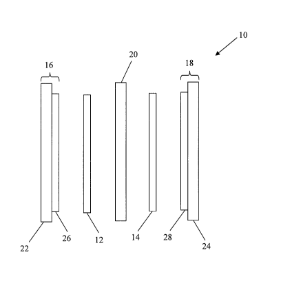
Figure 1 is a schematic illustration of a membrane electrode assembly.
Figure 2 is a graph showing polarization curves for fuel cells having a
platinum electrocatalyst and a platinum-cobalt alloy electrocatalyst for the
cathode
electrode, both in combination with a Nafion ionomer.
DETAILED DESCRIPTION
In the following description, certain specific details are set forth in order
to provide a thorough understanding of various embodiments of the present
description.
However, one skilled in the art will understand that the invention may be
practiced
without these details. In other instances, well-known structures associated
with fuel
cells, fuel cell stacks, and fuel cell systems have not been shown or
described in detail
to avoid unnecessarily obscuring descriptions of the embodiments.
Unless the context requires otherwise, throughout the specification and
claims which follow, the word "comprise" and variations thereof, such as
"comprises"
and "comprising" are to be construed in an open, inclusive sense, that is as
"including,
but not limited to".
Reference throughout this specification to "one embodiment" or "an
embodiment" means that a particular feature, structure or characteristic
described in
connection with the embodiment is included in at least one embodiment of the
present
description. Thus, the appearances of the phrases "in one embodiment" or "in
an
embodiment" in various places throughout this specification are not
necessarily all
referring to the same embodiment. Furthermore, the particular features,
structures, or
characteristics may be combined in any suitable manner in one or more
embodiments.
Figure 1 shows a schematic illustration of an exemplary membrane
electrode assembly 10 ("MEA"). As mentioned earlier, MEAs typically include
electrocatalyst layers 12,14 disposed between gas diffusion layers 16,18
("GDL") and a
proton exchange membrane 20 ("PEM"). Electrocatalyst layers 12,14 usually
contain
an electrocatalyst, such as a noble metal, non-noble metal, and/or alloys
thereof,
combined with an ionomer to increase proton conductivity within the
electrocatalyst
layers. GDLs 16,18 typically includes a substrate 22,24, such as carbon fiber
paper, and
4
CA 02668895 2009-05-06
WO 2008/058199 PCT/US2007/083954
an optional sublayer 26,28, such as a layer comprising carbonaceous particles
and a
binder, for example, PTFE and/or an ionomer.
As mentioned earlier, an important property of the electrocatalyst layer is
water management because it has a large influence on performance. If the
electrocatalyst layer cannot adequately remove excess product water, fuel cell
performance will be adversely affected due to excessive mass transport losses,
particularly when operating with air as the oxidant at high current densities
where large
amounts of water are produced. In particular, it has been found that certain
electrocatalysts, such as platinum-cobalt alloy electrocatalysts, have lower
kinetic losses
than pure platinum catalysts. This performance gain is not realized, however,
with
increasing current densities.
As shown in Figure 2, two MEAs having the same anode electrode and
same membrane, but different cathode electrocatalysts, were tested for fuel
cell
performance. The anode electrocatalyst was platinum on a graphite support and
the
loading was 0.1 mg Pt/cm2. The membrane was NRE211, a Nafiori -based polymer
electrolyte membrane supplied by E.I. Du Pont de Nemours and Company. The
cathode
electrocatalyst for one of the MEAs was platinum on a graphite support and
mixed with
a Nafion binder, while the cathode electrocatalyst for the other MEA was a
platinum-
cobalt alloy on a graphite support and mixed with a Nafiori binder. Both of
these
cathodes had a loading of 0.4 mg Pt/cm2. At 1.0 A/cm2, the testing conditions
were as
follows:
Fuel type 80% H2, balance N2
Fuel stoichiometry 1.8
Fuel pressure 2.2 bara
Fuel relative humidity 60%
Air stoichiometry 1.8
Air ressure 2.0 bara
Air relative humidity 60%
Coolant Inlet Temperature 65 C
Coolant Outlet Temperature 79 C
5
CA 02668895 2009-05-06
WO 2008/058199 PCT/US2007/083954
It is believed that electrocatalyst layers having a platinum-cobalt alloy
tend to have higher mass transport loss at high current densities than
electrocatalyst
layers containing pure platinum due to water retention. Thus, incorporation of
a
hydrophobic additive, which is compatible with the catalyst layer components,
into such
an electrocatalyst layer decreases water retention and enhances fuel cell
performance at
high current densities.
Polyfurfuryl alcohol (PFA) has been found to be a particularly suitable
hydrophobic additive for electrocatalyst layers for electrochemical fuel cells
because it
polymerizes at a temperature below the decomposition temperature of most
ionomers,
such as Nafion . The literature has shown that Nafiori membranes for direct
methanol
fuel cells have been made by in-situ acid-catalyzed polymerization of furfuryl
alcohol
within Nafion structures. It has been suggested that the hydrophilic nature
of the
monomeric furfuryl alcohol allows uniform and thorough penetration into the
hydrophilic structure of Nafion , thereby forming a Nafiori -PFA nanocomposite
membrane with reduced methanol permeation. Methanol permeation problems are
encountered in direct methanol fuel cells due to the use of liquid methanol
fuels, but not
for fuel cells operating on gaseous fuels, such as hydrogen gas.
Without being bound by theory, when PFA is employed in the
electrocatalyst layer having an ionomer, PFA imparts at least partial
hydrophobicity
within its relatively hydrophilic ionomer network, thus altering the water
management
properties of the electrocatalyst layer. Furthermore, ion conductivity should
not be
affected if PFA exists in the appropriate amounts. PFA may also enhance the
tensile
and/or adhesive strength between the electrocatalyst and the ionomer in the
electrocatalyst layer (thereby decreasing dimensional change of the
electrocatalyst layer
due to hydration/dehydration), and may prevent cracks from forming on the
surface of
the electrocatalyst layer.
In one embodiment, PFA is uniformly distributed within the
electrocatalyst layer. In other embodiments, PFA is non-uniformly distributed
within
the electrocatalyst layer. For example, the concentration of PFA through the
thickness
of the electrocatalyst layer may be varied in the z-direction (i.e., from the
PEM to the
6
CA 02668895 2009-05-06
WO 2008/058199 PCT/US2007/083954
GDL). Additionally, or alternatively, the concentration of the PFA in the
electrocatalyst
layer may be varied in the xy-direction (i.e., with respect to a surface of
the
electrocatalyst layer), for example, from an inlet of the fuel cell to the
outlet of the fuel
cell.
In further embodiments, PFA may also be in a layer form, for example,
as a layer between the electrocatalyst layer and the PEM or as a layer between
the
electrocatalyst layer and the GDL to enhance its hydrophobic properties.
Again, PFA
may be uniformly or non-uniformly distributed in the xy-direction.
The amount of PFA in the resulting electrode after polymerization may
range from, for example, about 0.1 wt% of the total ionomer in the
electrocatalyst layer
to about 20 wt% of the total ionomer in the electrocatalyst layer, depending
on its
penetration into the ionomer of the electrocatalyst layer. For example, if PFA
is
dispersed within the electrocatalyst layer, then the amount of PFA in the
resulting
electrode after polymerization is preferably less than 8 wt% of the total
ionomer in the
electrocatalyst layer. This is because it has been shown in the literature
that ion
conductivity of the membrane is negatively affected if the amount of PFA is
greater
than 8 wt% of the total ionomer. However, if the PFA is applied as a layer
onto the
electrocatalyst layer (i.e., between the electrocatalyst layer and the GDL),
then the
amount of PFA in the resulting electrode after polymerization may be higher,
for
example, less than 20 wt% of the total ionomer in the electrocatalyst layer,
thereby
forming a gradient in hydrophobicity in the z-direction of the electrocatalyst
layer. A
higher amount of PFA can be tolerated in this case because the affect on
proton
conductivity through the electrocatalyst layer is not significantly impacted
if PFA is
applied as a layer and without significant penetration into the
electrocatalyst layer.
Methods of making electrocatalyst layers and MEAs using electrocatalyst
compositions comprising PFA are discussed hereinbelow.
The electrocatalyst composition typically comprises an electrocatalyst,
such as a noble metal, for example, platinum, ruthenium, and iridium; a non-
noble
metal, for example, cobalt, nickel, iron, chromium, and tungsten; or
combinations or
alloys thereof. In specific embodiments, the electrocatalyst is a platinum-
cobalt alloy.
In other embodiments, the electrocatalyst may be a non-noble metal, such as
those
7
CA 02668895 2009-05-06
WO 2008/058199 PCT/US2007/083954
described in published U.S. Appl. No. 2004/0096728. The electrocatalyst may be
supported on an electrically conductive material, such as a carbonaceous or
graphitic
support material, for example, a carbon black or carbide, or other oxidatively
stable
supports. The electrocatalyst composition may optionally include a pore
former, such
as methyl cellulose, durene, camphene, camphor, and naphthalene, that is
removed in
the process of making the electrocatalyst layer to increase the porosity
thereof. In
addition, the electrocatalyst composition may optionally contain an ionomer,
such as,
but not limited to, a perfluorinated ionomer, a partially fluorinated ionomer,
or a non-
fluorinated ionomer; and an optional solvent, for example, a polar aprotic
solvent, such
as N-methylpyrrolidinone, dimethylsulfoxide, and N,N-dimethylacetamide.
Furthermore, the electrocatalyst composition may optionally include other
additives,
such as carbonaceous particles and carbon nanotubes and/or nanofibres.
In one embodiment, monomeric furfuryl alcohol is mixed with the
electrocatalyst composition by any method known in the art, such as stirring,
shear
mixing, microfluidizing, and ultrasonic mixing. The monomeric furfuryl alcohol
may
be employed in the form of a neat solution or dispersed in a solvent, such as
isopropanol, ethanol, methanol, deionized water, or mixtures thereof, before
adding to
the electrocatalyst composition. Optionally, an acid catalyst may be added to
the
electrocatalyst composition to induce and/or enhance the polymerization
process.
The electrocatalyst composition may be applied onto a sheet material by
any method known in the art, such as knife-coating, slot-die coating, dip-
coating,
microgravure coating, spraying, and screen-printing. In one embodiment, the
sheet
material is the surface of the electrocatalyst layer. In other embodiments,
the sheet
material may be a transfer material such as polytetrafluoroethylene,
polyester, and
polyimide sheet materials that can be used to decal transfer the
electrocatalyst layer to a
surface of the GDL to form a gas diffusion electrode, or to a surface of the
PEM to form
a catalyst-coated membrane (CCM).
In another embodiment, the electrocatalyst composition may be applied
onto a surface of the sheet material to form an electrocatalyst layer, and
then monomeric
furfuryl alcohol is applied onto a surface of the electrocatalyst layer by any
method
known in the art, such as those described above. In some embodiments,
monomeric
8
CA 02668895 2009-05-06
WO 2008/058199 PCT/US2007/083954
furfuryl alcohol may also be applied to the surface of the sheet material
before
application of the electrocatalyst composition.
In this embodiment, the monomeric furfuryl alcohol and electrocatalyst
layer may be subjected to impregnation conditions prior to polymerization to
create a
non-uniform distribution of furfiuyl alcohol in the electrocatalyst layer, for
example, a
gradient of furfuryl alcohol through the thickness of the electrocatalyst
layer. In further
embodiments, monomeric furfuryl alcohol may be homogeneously impregnated into
the
electrocatalyst layer by using a sufficient amount of monomeric furfuryl
alcohol and/or
subjecting the monomeric furfuryl alcohol and electrocatalyst layer to the
appropriate
impregnation conditions. Impregnation of the monomeric furfuryl alcohol into
the
electrocatalyst layer may be controlled by varying the amount of furfuryl
alcohol and/or
the impregnation conditions, such as the impregnation temperature and time, to
achieve
the desired gradient through the thickness of the electrocatalyst layer.
Polymerization of the monomeric furfuryl alcohol may occur before
and/or during bonding of the MEA. For example, the monomeric furfuryl alcohol
may
be polymerized during or after application to the sheet material, and before
assembling
the MEA. Alternatively, polymerization occurs simultaneously with bonding of
the
MEA components by assembling an MEA with an electrocatalyst layer containing
monomeric (unpolymerized) furfuryl alcohol and then subjecting the MEA to
bonding
conditions that are similar to the required polymerization conditions. In yet
another
example, the monomeric furfuryl alcohol may be partially polymerized during or
after
application to the sheet material, and then further polymerized during MEA
bonding.
The polymerization conditions may include a polymerization
temperature, for example, heating to a temperature of between about 80 C and
about
140 C, and a polymerization time of about 5 seconds to about 15 minutes. The
polymerization time will be dependent on the polymerization temperature and
the
amount of furfuryl alcohol. For instance, the polymerization time from about 5
to 10
minutes for a low polymerization temperature and a high amount of furfuryl
alcohol, but
may range from about 1 to 2 minutes for a high polymerization temperature and
a low
amount of furfuryl alcohol. In some instances, the furfuryl alcohol may be
cross-linked
by exposure to ultraviolet rays, for example, by exposure to a mercury lamp.
9
CA 02668895 2009-05-06
WO 2008/058199 PCT/US2007/083954
In some embodiments, the amount of furfuryl alcohol and/or degree of
polymerization of the furfuryl alcohol in or on the electrocatalyst layer is
non-uniform
in the xy-direction to preferentially control the hydrophobic properties in
different
regions of the fuel cell. In one embodiment, a higher concentration of
monomeric
furfuryl alcohol and/or a greater degree of polymerization of the monomeric
furfuryl
alcohol may be employed in regions of the electrocatalyst layer that tends to
be wetter
during fuel cell operation (for example, the outlet region of the fuel cell in
comparison
to the inlet region) to improve water removal therefrom. Further, the loading
of the
electrocatalyst composition with monomeric furfuryl alcohol may be varied when
it is
applied to the sheet material. In another example, the loading of monomeric
furfuryl
alcohol may be varied when it is applied to the electrocatalyst layer. In yet
another
example, the polymerization conditions may be varied along the xy-direction of
the
electrocatalyst layer to vary the degree of polymerization.
In further embodiments, an ionomer layer may also be employed
between the PEM and electrocatalyst layer and/or between the electrocatalyst
layer and
GDL. The ionomer layer may also contain monomeric furfuryl alcohol and then
polymerized after application to a surface of the PEM and/or the
electrocatalyst layer,
for example, polymerizing immediately after application or polymerizing during
MEA
bonding. Again, the ionomer layer may be applied by any method known in the
art,
such as those described above, and may be uniform or non-uniform with respect
to the
planar surface of the catalyst layer.
The following examples are provided for the purpose of illustration, not
limitation.
Example 1
Polymerization of furfuryl alcohol to form an electrode
An electrocatalyst composition is made by mixing 662 grams of 10% by
weight Nafion solution with 132 grams of a platinum-containing catalyst
powder, 2
grams of monomeric furfuryl alcohol, 6 grams of isopropanol, and 290 grams of
de-
ionized water. The mixture is then mixed using an ultrasonic mixer and then
sprayed
onto a fluid diffusion layer comprising a carbon fiber paper and a microporous
CA 02668895 2009-05-06
WO 2008/058199 PCT/US2007/083954
carbonaceous layer. The resulting electrode is then subjected to a temperature
of about
140 C for about 2 to 10 minutes to polymerize the monomeric furfuryl alcohol,
thereby
producing an electrode with PFA.
Example 2
Polymerization of furfuryl alcohol to form a catalyst-coated membrane
A solution of monomeric furfuryl alcohol is prepared by mixing 6 grams
of monomeric furfuryl alcohol with 12 grams of isopropanol and 6 grams of de-
ionized
water. The solution is then sprayed onto the cathode electrocatalyst layer of
a CCM.
The monomeric furfuryl alcohol is allowed to penetrate into the cathode
electrocatalyst
layer for about 1 hour at 20 C. After penetration, the CCM is heated to about
140 C for
about 2 to about 10 minutes to polymerize the monomeric furfuryl alcohol,
thereby
producing a CCM with PFA in the cathode electrocatalyst layer.
Example 3
Polymerization of furfuryl alcohol as a layer on a carbon/Nafiori subla yer
A solution of monomeric furfuryl alcohol was prepared by mixing 6
grams of monomeric furfuryl alcohol (98% Lancaster) with 12 grams of
isopropanol
and 6 grams of de-ionized water. The solution was then sprayed at room
temperature
onto a GDL having a sublayer containing carbon black and Nafion on one
surface of
the substrate. The sprayed GDL was then placed onto a hot plate at 140 C for
about 10
minutes to polymerize the furfuryl alcohol. The final loading of PFA was about
45wt%.
The polymerized GDL was then subjected to a mercury intrusion
porosimetry test using the Autopore III supplied by Micromeritics Instrument
Corporation, and a series of through-plane permeability tests using the 58-21
Roughness
and Air Permeance Tester supplied by Testing Machines (TMI Inc.). (A through-
hole
was bored through the bottom jig of the tester and a rubber seal was placed
around the
test piece so that air was forced from the top jig to the bottom jig through
the test piece.)
Mercury intrusion porosimetry tests showed that the average pore
diameter shifted from about 0.67 microns with no PFA to 1.11 microns with PFA,
while
through-plane permeability tests showed that the air permeability increase
from an
11
CA 02668895 2009-05-06
WO 2008/058199 PCT/US2007/083954
average of 129 mL/min with no PFA to an average of 183 mL/min with PFA. The
furfuryl alcohol likely shrinks as it polymerizes, thus pulling the pores
wider apart and
increasing the size and through-plane permeability thereof. This increase in
pore size
and through-plane permeability may improve water removal and reactant
accessibility
when PFA is employed in the electrocatalyst layer, in addition to increasing
the
hydrophobicity of the electrocatalyst layer.
All of the above U.S. patents, U.S. patent application publications, U.S.
patent applications, foreign patents, foreign patent applications and non-
patent
publications referred to in this specification and/or listed in the
Application Data Sheet,
are incorporated herein by reference, in their entirety.
While particular steps, elements, embodiments and applications of the
present invention have been shown and described herein for purposes of
illustration, it
will be understood, of course, that the description is not limited thereto
since
modifications may be made by persons skilled in the art, particularly in light
of the
foregoing teachings, without deviating from the spirit and scope of the
present
disclosure. Accordingly, the invention is not limited except as by the
appended claims.
12