Note: Descriptions are shown in the official language in which they were submitted.
CA 02668976 2009-06-15
WH 13509 CA
TITLE: NETWORK MAPPING FUNCTION
FIELD OF THE INVENTION
The present invention relates to fiber optic
network systems, and in particular, to a system used to
simplify the mapping of patch terminals relative to an
upstream power patch panel.
BACKGROUND OF THE INVENTION
There are many applications where it is common to
have a fiber optic network system with a series of fiber
to copper patch terminals provided at the downstream end
of the system. The fiber to copper patch terminals allow
users to connect to the system in a number of different
ways. The fiber to copper patch terminals are connected
to a power patch panel provided in a computer room, for
example, by means of a multi-fiber cabling system. The
power patch panel includes a plurality of patch panel
modules in communication with particular patch terminals.
Typically, this type of system operates using an Ethernet
communication protocol, and the signals are converted by
the fiber to copper patch terminal, and transmitted and
received from the system. The patch terminals include a
transceiver to receive and transmit signals over the
fiber optic system.
In small network systems, it is relatively
straightforward to map or to trace the actual cable
connections between a fiber to copper patch terminal and
a power patch panel provided at a central location. As
the system expands, this problem becomes more difficult
and it is often a key consideration whenever any
difficulties occur with a system. In large networked
systems, a detailed mapping arrangement is produced to
allow a technician to trouble shoot the system more
- 1 -
CA 02668976 2009-06-15
WH 13509 CA
effectively. Unfortunately, such mapping procedures are
often not maintained, or unauthorized changes to the
system occur.
It would be desirable to have a simple
arrangement for identifying or confirming the
communication path between a fiber to copper patch
terminal and a power patch panel provided upstream
thereof.
SUMMARY OF THE INVENTION
A fiber optic network system according to the
present invention comprises a power patch panel connected
to a series of fiber to copper patch terminals by fiber
optic cabling. The power patch panel includes a plurality
of patch panel modules and each module has a plurality of
ports. Each port includes an indicator that is activated
upon receipt of a location identification transmission
signal originating from a connected patch terminal. Each
patch terminal includes an optical transceiver that
transmits and receives signals in accordance with a
communication protocol that includes a non-transmit /
receive period if a detected interruption in
communication with the associated patch panel module
occurs. Each patch terminal includes a selectively
activated location identification function that when
activated causes the patch terminal to produce a non-
transmit / receive period recognized by the protocol.
The location identification function causes the optical
transceiver to transmit an identification signal. The
power patch panel module, upon receipt of a location
identification signal, produces a visual indication
identifying the port that received the location
identification signal. With this arrangement, a
technician can cause the user patch terminal to transmit
a location identification signal, and then inspect the
- 2 -
CA 02668976 2009-06-15
WH 13509 CA
power patch panel and determine the port used to
communicate with the particular user patch terminal.
The power patch panel, as well as the user patch
terminal, advantageously uses a characteristic of the
communication protocol to transmit a location
identification signal during a period where conventional
signals between the power patch panel and the user patch
terminal are being ignored. In a preferred embodiment,
the non-transmit / receive period is repeatedly created
whereby the communication protocol continues to ignore
any signals for an extended period of time.
In a preferred embodiment of the invention, the
power patch panel includes a light source associated with
each port, and the light source is activated when a
location identification signal is received by the
respective port.
In a further aspect of the invention, the
location identification function of each patch terminal
includes a manual switch which produces the location
identification signal when activated.
In a further aspect of the invention, the
communication protocol used in the fiber optic network
system is an Ethernet communication protocol.
In yet a further aspect of the invention, the
communication protocol includes a resettable time
interruption period where signals received by the user
patch panel are not processed according to the
communication protocol. The resettable time interruption
period is initiated when an idle level of light is not
received by the respective transceiver of either patch
panel.
- 3 -
CA 02668976 2009-06-15
WH 13509 CA
In yet a further aspect of the invention, the
manual switch, when activated, causes the transceiver to
pulse between states producing at least an idle level of
light to a state not producing an idle level of light
sufficient to maintain a state where signals of the
transceiver are not processed using the communication
protocol.
An improved fiber to copper patch terminal,
according to the present invention includes an operating
protocol controlling an optical transceiver for
transmission and reception of signals and selectively
activated circuitry to produce a condition where normal
communication with a connected power patch panel module
is temporarily interrupted. The circuitry during the
interruption of normal communication causes the
transceiver to transmit a location identification signal
recognizable by the power patch panel module. Preferably
the module produces a visual indication when a location
identification signal has been received.
BRIEF DESCRIPTION OF THE DRAWINGS
Preferred embodiments of the invention are shown
in the drawings, wherein:
Figure 1 is a schematic overview of a fiber optic
network system;
Figure 2 is a partial enlargement of the user
patch terminal shown in Figure 1;
Figure 3 is a partial enlargement of the power
patch panel module shown in Figure 1;
Figure 4 is a schematic view of a user patch
terminal; and
- 4 -
CA 02668976 2009-06-15
WH 13509 CA
Figure 5 is a schematic view of additional
circuitry provided for the power patch panel.
DETAILED DESCRIPTION OF THE PREFERRED EMBODIMENTS
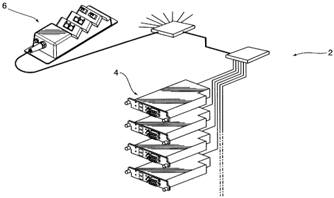
The fiber optic network system 2 shown in Figure
1 illustrates a single power patch panel module 4;
however in practice there will be a series of modules
that are part of a power patch panel (not shown). Figure
1 also illustrates a fiber to copper patch terminal 6;
however the network would include a host of these patch
terminals. Typically, the power patch panel module 4 is
combined with other modules in a patch panel located in a
computer room, and is connected to a high speed digital
network. High speed multi-fiber optic cabling is
provided between the power patch panel modules and the
various user patch terminals 6. Each user patch terminal
6 includes a series of ports and these ports include
Ethernet ports for connection to computer equipment and
may additionally include fiber optic ports.
The communication protocol is typically an
Ethernet communication protocol, and each patch terminal
6 converts signals and includes a transceiver for
appropriately transmitting signals across the fiber
network and receiving signals.
As shown in Figure 3, the power patch panel
module 4 is shown with two ports 12 and 14 with each port
including a light emitting indicator 16 and 18
respectively. These light emitting indicators will be
activated when a location signal is received by the
particular port. This aspect will be further explained
with respect to Figures 4 and 5.
5 -
CA 02668976 2009-06-15
WH 13509 CA
Figure 4 is a schematic that illustrates certain
additional circuitry that is associated with the patch
terminal 6. The patch terminal 6 includes an optical
transceiver shown as 30 having a light transmission
source indicated as 32 in combination with the receiver
34. With this arrangement, the transceiver 30 transmits
signals to the fiber optic cable indicated as 24 and
receives optical signals from the fiber optic cable. The
Ethernet communication protocol used for transmission
over the fiber optic network system 2 includes a time
reset function in the event an idle level of light is not
received by the transceiver 30. The protocol includes a
certain time delay before attempting to re-establish
communication. This feature of the protocol is used by
the present system for transmitting a location
identification signal.
As shown in Figure 4, a manual switch 54 is shown
that is used to activate the pulse circuit 50. The pulse
circuit 50 is connected to the optical transceiver 30 and
causes the transceiver to cycle between a transmission
state where light is being transmitted by the transceiver
to a non-active state where light is not being
transmitted. The pulse circuit is such that it will
maintain the protocol in a temporary suspension condition
as an idle level of light is not being received. By
pulsing the signal to the optical transceiver a pulse
signal is transmitted over the fiber optic cable 24.
This pulse signal can be an identification signal
recognized by the power patch panel module, or the signal
can also include details of a location address indicated
as 52 shown in Figure 4.
The pulse signal is received by the power patch
panel module 4 over the fiber optic cable indicated as 24
in Figure 5. This signal is processed by the processer
64 which also includes a watching circuit indicated as
- 6 -
CA 02668976 2009-06-15
Wk 13509 CA
66. The watching circuit is used to recognize a pulse
location identification signal from a patch terminal, and
when this particular signal has been recognized, the
watching circuit will activate the mapping indicator
shown as 68.
With this arrangement, a technician seeking to
identify the particular port on the power patch panel
module 4 that a particular user patch terminal 6 is
connected to, can activate the manual switch 54 provided
on the patch terminal 6. This activates the pulse
circuit, and turns the optical transceiver 30 on and off.
The watching circuit 66 of the power patch panel module 4
recognizes the pulsed signal and illuminates the mapping
indicator 68. The technician, after activating the
switch 54, can go to the power patch panel and look at
the various modules for a lit indicator 68. This
provides a simple arrangement for allowing a technician
to effectively map a network. The user patch terminal 6
does not convert signals as the time out function has
been activated by the pulsed signal.
Figure 4 also includes the watch circuit 56 and
it is possible for the power patch panel module 4 to also
include an activation mechanism for sending a pulsed
signal. In this way, a particular power patch panel
module 4 could be activated and the mapping indicator 58
would be illuminated.
From the above, it can be appreciated that the
network mapping function is based on the use of a
secondary communication path established using two
control characteristics of current optical transceivers.
When a transceiver receives an idle level of light from
the opposite end of a fiber link, a "signal detect (SD)"
signal becomes active at the receiving end. The
transceiver also includes a TX Disable signal, and when
7 -
CA 02668976 2009-06-15
WH 13509 CA
this signal is made active at the transmitting end, it
shuts down the transmitting element in the transceiver so
that the idle level of light is removed. In normal
operation the TX Disable is inactive, and the transceiver
increases and decreases the light level around the idle
point to transmit Ethernet packets of information. Also
in the normal operation at the receive end, the SD signal
remains active, signaling that the idle level of light is
present and that digital data can be received.
The structure of the present invention provides
for secondary communication by switching the TX Disable
signal at a certain rate and duty cycle so that the
signal detect line at the other end of the path switches
in a light pattern. As soon as the receiving transceiver
SD signal goes inactive, all Ethernet communication is
ceased, and the system waits for it to reestablish after
a predetermined time period. During this time period,
the pulsing SD line is ignored by the Ethernet processing
arrangement, but used by the network mapping function to
send and receive serial number and position data. In the
simple command and illuminate function, locate LEDs can
show maintenance staff the opposite end of an optical
link by pulsing TX Disable at the end in question. In a
more sophisticated application, the network mapping
function can include a table showing the connectivity of
a large network, and can be presented in a table format.
The present system is also capable of being automated and
the particular patch panels can be instructed to
determine a connected location patch terminal, and have
the patch terminal transmit location information. Thus,
with the above it is possible to provide automated
mapping function in addition to the manual mapping
function as previously described.
Although various preferred embodiments of the
present invention have been described herein in detail,
- 8 -
CA 02668976 2009-06-15
WH 13509 CA
it will be appreciated by those skilled in the art, that
variations may be made thereto without departing from the
spirit of the invention or the scope of the appended
claims.
- 9 -