Note: Descriptions are shown in the official language in which they were submitted.
CA 02669039 2009-05-08
Device for treating wounds
Technical field
The invention relates to a device for treating wounds
according to the preamble of claims 1 and 23.
Prior art
Open wounds that are too large or too badly inflamed to
heal independently have long been a problem in
medicine. It has been found that wound treatment using
low pressure stimulates, supports and accelerates the
healing of the wound. This type of treatment is known
as wound drainage.
US 5 636 643, for example, discloses a wound drainage
device with a fluid-impermeable and gas-impermeable
rigid cover that is placed over a wound and is secured
to the healthy skin outside the margins of the wound.
Underneath the cover, a foam is placed onto or into the
wound. A negative pressure is generated in the cover
from outside by means of a vacuum pump in order to
accelerate the healing of the wound.
WO 03/018098 also describes a device for treating
wounds, with a cover and with a porous pad that is
placed onto the wound underneath the cover. This
document proposes automated oscillation of the negative
pressure in order to stimulate the healing of the
wound.
WO 2006/056408 proposes that the cover be provided with
supply devices for treatment substances. These
treatment substances are removed together with the
wound secretions through a drainage device.
CA 02669039 2009-05-08
- 2 -
WO 2006/048246 discloses a multicomponent dressing for
wound treatment by means of negative pressure. This
dressing comprises superabsorbent polymers, wherein the
absorbed wound secretions remain bound to polymers in
the wound cavity.
In US 2006/0155260, the wound is cleansed with a fluid
and a closed circuit is used.
WO 2004/071279 describes a wound treatment device that
comprises sensors for monitoring the healing of the
wound.
WO 2006/081221 further proposes the treatment of wounds
by phototherapy.
Disclosure of the invention
It is therefore an object of the invention to create a
device for treating wounds that can be used for
different sizes of wounds.
This object is achieved by a device for treating wounds
that has the features of claim 1.
The device according to the invention for treating
wounds of a patient, preferably by means of low
pressure, comprises a covering for forming a low-
pressure chamber over the wound, wherein the covering
can be secured on the skin surrounding the wound. After
the covering has been applied to the wound and secured
on the skin, the shape of the covering can change from
a basic shape to a predefined shape for use.
This wound covering can easily be adapted specifically
to the corresponding wound. It avoids a mechanical
pressure on the wound bed but still permits a
contraction of the wound. It is also relatively simple
CA 02669039 2009-05-08
- 3 -
to use, such that application to the wound and removal
from the wound take little time.
The covering can preferably change automatically from
the basic shape to the shape for use. This has the
advantage that touching the wound, through incorrect
use of the covering, can be largely avoided.
The covering is preferably made at least partially,
preferably entirely, from a material with shape memory.
The covering preferably has the shape for use at a
temperature that corresponds approximately to a body
temperature of the patient. The basic shape is
preferably present at room temperature (i.e. about
20 C). All suitable materials with shape memory can be
used, in particular polymers or metals.
Additionally or alternatively, however, the covering
can also be provided with at least one mechanical
element by means of which its shape can be changed.
This element can be a restoring spring, for example.
In one embodiment, the covering comprises a base
element without shape memory and at least one
subcomponent with shape memory that is arranged on or
in this base element, wherein the at least one
subcomponent extends over the base element in such a
way that, upon changing shape, it forces the base
element to undergo a predetermined change of shape.
In another embodiment, the covering comprises a profile
element, which can be bent to form a ring, and a cover
sheeting or film that can be stretched over the ring.
The profile element can preferably change its profile
height in a controlled manner mechanically, e.g. by a
spring, by shape memory, by being inflated, or by
virtue of its coefficient of thermal expansion.
CA 02669039 2009-05-08
- 4 -
One or more of the following means can be arranged in
the covering: an ultrasound transmitter, a light
source, a temperature sensor, a sensor for measuring
the humidity, a sensor for measuring the flow of blood,
a sensor for measuring the bacterial colonization, a
heating means.
The device according to the invention is preferably
used for wound drainage by low pressure. However, it
can also be used for other wound treatments. Moreover,
a wound is understood here not only as an open area of
skin but also as skin anomalies or other tissue
defects.
The system according to the invention for treating
wounds comprises a device of the abovementioned type
for treating wounds and also a vacuum pump that can be
connected to said device so as to generate a low
pressure in a cavity generated by the device for
treating wounds.
In the method according to the invention for treating
wounds, a covering is secured on the wound, wherein the
covering has a basic shape when being secured, and
wherein the covering, after it has been secured in
place, is changed to a shape for use.
Other advantageous embodiments and variants of the
method are set forth in the dependent claims.
Brief description of the drawings
The subject matter of the invention is explained below
on the basis of preferred illustrative embodiments
depicted in the attached drawings, in which:
Figure 1 shows a cross section through a covering
according to the invention, in a basic
CA 02669039 2009-05-08
- 5 -
shape prior to its use, according to a
first embodiment;
Figure 2a shows a cross section through the
covering according to Figure 1 in a
basic shape;
Figure 2b shows a perspective view of the covering
according to Figure 2a;
Figure 3a shows a cross section through a wound
and surrounding tissue;
Figure 3b shows a perspective view of the wound
according to Figure 3a;
Figure 4a shows a cross section through the wound
according to Figure 3a, with the
covering according to Figure 2a placed
over it;
Figure 4b shows a perspective view of the wound
and covering according to Figure 4a;
Figure 5a shows a cross section through the wound
and through the drainage device secured
over the latter in a basic shape;
Figure 5b shows a perspective view of the wound
and the device according to Figure 5a;
Figure 6 shows a cross section through the wound
and the device according to Figure 5a in
a shape for use;
Figure 7a shows a graphic representation of the
applied vacuum as a function of time;
Figure 7b shows a graphic representation of a
hydrogel application as a function of
time;
Figure 7c shows a graphic representation of an
irrigation as a function of time;
CA 02669039 2009-05-08
- 6 -
Figure 8a shows a cross section through the wound
and drainage device in a hydrogel
application in a first state and
Figure 8b in a second state;
Figure 9 shows a cross section through the
drainage device according to the
invention in a second embodiment;
Figure 10 shows a cross section through the
drainage device according to the
invention in a third embodiment;
Figure 11a shows a cross section through the
drainage device according to the
invention in a fourth embodiment;
Figure 11b shows a graphic representation of the
measurement of the flow of blood;
Figure 12 shows a cross section through the
drainage device according to the
invention in a fifth embodiment;
Figure 13a shows a perspective view of a sixth
embodiment of the drainage device
according to the invention in a basic
shape and
Figure 13b in a shape for use;
Figure 13c shows a cross section through the device
according to Figure 13b;
Figure 14 shows a view of a first variant of a
subcomponent according to the invention;
Figure 15 shows a view of a second variant of a
subcomponent according to the invention;
CA 02669039 2009-05-08
- 7 -
Figure 16a shows a perspective view of a profile
element of a drainage device according
to a seventh embodiment;
Figure 16b shows the profile element according to
Figure 16a in an arrangement around a
wound, and
Figure 16c shows a cross section through the
drainage device according to the seventh
embodiment.
Ways of carrying out the invention
Figures 1 to 6 show a first preferred embodiment of the
device according to the invention for treating wounds,
in particular a wound drainage device. The starting
material is a cover plate 1 according to Figure 1,
which preferably has a plane configuration,
particularly a plane-parallel configuration. This plate
1 has at least two, and possibly also three, four or
more through-openings 10, 10' extending preferably at
right angles to the plate 1. However, they can also
extend at an angle not orthogonal to the plate 1.
The plate 1 has a shape memory that can preferably be
thermally activated. A predefined or preprogrammed
shape is preferably adopted at human body temperature.
The material is preferably an SMP, i.e. a shape memory
polymer, for example a block copolymer, e.g. a wax-
elastomer composite. The plate is preferably rigid or
at least self-supporting, such that its shape changes
only under the effect of an external force and in
particular such that it maintains its basic shape, and
also its shape for use described below, without being
supported across its entire surface area. The shape for
use should in particular also be maintained in the
event of a pressure difference on the two opposite
sides. The plate 1 preferably has a thickness of 1 to 6
CA 02669039 2009-05-08
- 8 -
mm. In another embodiment, the shape memory polymer can
be stimulated by magnetism or light. This applies also
to other embodiments of the invention, in particular to
the embodiments described further below.
This cover plate 1 is now adapted for use to the size
of the wound. A corresponding wound W is shown in
Figures 3a and 3b. According to Figures 2a and 2b, the
plate 1 is now accordingly cut to size, with a desired
edge width 12 simply being cut off or broken off at two
opposite ends. A cover plate blank 11 with the two
through-openings 10, 10' remains. This blank 11 is now
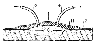
placed over the wound W according to Figures 4a and 4b
such that a cavity C is formed. According to Figures 5a
and 5b, the blank 11 is fixed in position by means of
an adhesive sheeting or film 2 or another suitable
fixing element. For this purpose, the edges of the
adhesive film 2 are affixed to healthy skin or tissue A
surrounding the wound W. The film 2 can also adhere to
the blank 11. However, it can also simply be stretched
over the latter without being connected to the film.
Moreover, a delivery tube 3 is inserted into the first
through-opening 10 and a drainage tube 4 is inserted
into the second through-opening 10'. The tubes 3, 4 can
also be fixed by means of the film 2 and/or they can be
fixed in position by fixing rings, clips, separate
adhesives or other suitable means.
As can be seen from Figures 5a and 5b, the blank 11
still has a basic shape when applied, here as a plane-
parallel plate. The basic shape could also be another
shape, for example it could curve inward or outward
relative to the cavity C, and it could also be
undulating or pyramid-shaped.
As can be seen now from Figure 6, the blank 11 adopts a
shape for use as soon as it has reached the temperature
CA 02669039 2009-05-08
- 9 -
of the surrounding tissue A or of the wound W. This
shape for use is preferably hood-shaped or dome-shaped,
directed outward away from the wound, as is indicated
by the vertical arrow. The height of the cavity C and
therefore the distance of the blank 11 from the wound
surface are thus increased. Mechanical pressure on the
wound bed and adherence of the covering are avoided.
Another important point is that the change of shape
causes a contraction of the wound, since the wound
margins are pulled inward, as is indicated by the
horizontal arrows, and the blank 11, which is also
rigid in the position of use, ensures that a constant
traction or pressure is applied to the wound margins
throughout the entire drainage procedure or wound
treatment.
If not already begun, the wound drainage can now be
started, i.e. a suitable low pressure can be applied
via the drainage tube 4. Wound secretions can also be
removed via the drainage tube 4. Moreover, means for
accelerating the healing and disinfection of the wound
can be supplied via the delivery tube 3, for example a
hydrogel 5, as is shown in Figures 8a and 8b. The wound
can also be irrigated, for example with Ringer's
solution.
Figures 7a to 7c show a possible relationship between a
vacuum application in the cavity C (Figure 7a), a
hydrogel application (Figure 7b) and an irrigation of
the cavity (Figure 7c). The three time axes t are
identical and an increment in each case designates 1
day d. As can be seen from Figure 7a, a pulsing
sinusoidal vacuum is applied over a long period of
time. According to the figure, it is about 125 mmHg,
preferably between 80 and 140 mmHg. The hydrogel
application is carried out over a much shorter period
than one day, preferably for 1 to 3 minutes in the
space of 1 to 2 days until the wound is wet. The same
CA 02669039 2009-05-08
- 10 -
applies to the irrigation, which is preferably done
before the wetting of the wound bed with hydrogel and
the application is not started until 0.5 to 2 hours
after the irrigation. Oxygenation can take place at the
same time as the application of the low pressure or as
an independent phase between the applications.
Moreover, the wound drainage device or the covering
used for this can be provided with additional
functions. Thus, as is shown in Figure 9, an ultrasound
transmitter 6 can be connected to the blank 11 and
transmits ultrasonic waves 61 into the cavity C. This
transmitter 6 can already be fitted in place by the
manufacturer and supplied as a component part of the
cover plate 1. However, it can also be secured in place
later on. For this purpose, the cover plate 1 can have
a corresponding recess or indentation. The transmitter
6 can be secured by adhesive, clips, welding, casting
or other suitable means. The ultrasound transmitter 6
is preferably operated by the same device that also
contains the vacuum source. In this case, it is
advantageous if the line 60 for the ultrasound
transmitter 6 is routed along the drainage tube 4.
Instead of the ultrasound transmitter 6, a light source
can also be present to transmit light into the cavity
C. The set-up corresponds to that of Figure 9 and the
above description also applies to the light source.
Ultrasound transmitter and light source can also be
used in combination in the wound drainage device. Both
in their own way stimulate the healing of the wound.
They can be used together with or instead of the
vacuum.
In addition of or instead of this transmitter or this
source, means for monitoring the healing of the wound
can also be connected to the blank 11. The details
given above relating to the time and nature of the
CA 02669039 2009-05-08
- 11 -
securing also apply here. One such means is, for
example, a temperature sensor and/or a hydrosensor 7,
which measures the moisture in the wound. This is
illustrated in Figure 10. Here too, the signal line 70
is preferably routed along the drainage tube 4 and the
data are evaluated and exploited for further treatment
in the device of the vacuum pump.
A further monitoring means is a flow sensor 8 according
to Figure 11a, which qualitatively measures the flow of
blood through the tissue A lying beneath the wound and
forwards the data via the signal line 80. Figure 11b
shows an example of a flow rate of the kind that can be
detected by the abovementioned sensor.
It is also possible to use other monitoring sensors,
however, for example a sensor for monitoring the
bacterial colonization.
Moreover, the device can be provided additionally or
alternatively with a heating element 9, in order to
maintain the desired temperature. This temperature can
be the optimum temperature for achieving the desired
shape memory of the blank 11. However, it can also be
the optimum temperature for healing of the wound. This
is illustrated in Figure 12. A resistance heating
element of a known type, preferably in a flat
configuration, is suitable in particular as heating
element 9. However, it is also possible to use a
heating element that can be activated by way of a
chemical reaction or another suitable heating element.
Here, the heating element 9 is arranged outside the
cavity C, on the side of the blank 11 directed away
from the latter, and is located under the adhesive film
2. However, it can also be arranged in the cavity C or
over the adhesive film 2. If suitable, the sensors and
sources described above can also be arranged outside
the cavity C.
CA 02669039 2009-05-08
- 12 -
Figures 13a to 13c show another embodiment of the
drainage device according to the invention and of its
covering. Here, the covering has a plate-shaped base
element 12 whose dimensions, like those of the blank
according to the above examples, can be chosen freely
and adapted to the wound. Subcomponents in the form of
longitudinal and transverse strips 13a, 13b are now
arranged on the base element 12 and fixedly connected
to the latter at least in some areas. The longitudinal
and transverse strips 13a, 13b extend approximately
perpendicular to one another. The base element 12 does
not have a shape memory, but these strips 13a, 13b do.
The base element is preferably made from a fluid-
impermeable polymer film and the strips 13a, 13b are
again made from a shape memory polymer or a shape
memory metal.
The strips 13a, 13b preferably act as contraction tapes
when they have reached the corresponding temperature
that activates the shape memory. Here too, this
temperature is preferably human body temperature, i.e.
about 37 C. The strips 13a, 13b are adapted in the
usual way to the size of the wound. The base element 12
and tapes 13a, 13b can be supplied as one unit and can
be together cut to the desired size. However, they are
preferably separate parts that are first adapted to the
corresponding wound and then joined together.
As can be seen from the arrows in Figure 13b, the
strips 13a, 13b change shape as the temperature changes
and, for example, adopt an undulating, shortened shape.
In this way, the base element 12 lying underneath them
also changes shape, in particular being drawn together.
This also leads to a contraction of the wound and to a
constant traction or pressure on the wound margins. The
acting forces F are also shown again in Figure 13c.
CA 02669039 2009-05-08
- 13 -
As can be seen from this figure, the cavity C in this
embodiment is preferably filled at least partially with
a wound bed filler F, for example a textile. A wound
bed filler of this kind is not needed in the other
embodiments and is also only optional here. It can,
however, be used also in the other embodiments. Here
too, the abovementioned sensors and sources can again
be used. Application of a vacuum is also possible.
Instead of the strips 13a, 13b, it is also possible to
use star-shaped subcomponents 13' (see Figure 14),
spiral-shaped subcomponents 13" (see Figure 15) or
other shapes produced from shape-memory materials.
Figures 16a to 16c show another embodiment of the
device according to the invention. Here, a bendable
profile element or cord 16 is present which, in the
normal state, is rectilinear or slightly curved, as can
be seen from Figure 16a. It can be applied in a ring
shape around the wound W, as is shown in Figure 16b. It
is held in its position by means of a cover film or
adhesive sheeting or film 15, which is placed over the
internal circle defined by the profile element 16, over
the profile element 16 itself and onto the healthy skin
outside the cord 16 and is affixed there to the skin.
Instead of a pressure-sensitive adhesive film, the film
can also be affixed to the margins by an adhesive tape.
However, it preferably also adheres on the profile
element 16. The film 15 can be provided with through-
openings for the tubes 3, 4, or it can simply be
pierced in order to create these openings.
When there is a negative pressure in the cavity C, a
force is applied to the film 15 by the atmospheric
external pressure. The force results in a perpendicular
force acting on the ring-shaped profile element 16, and
this causes a contraction of the wound. It is thus
CA 02669039 2009-05-08
- 14 -
possible, even without using a sponge in the wound bed,
to avoid the film 15 attaching itself to the wound.
Moreover, the profile height of the ring 16 preferably
increases during use. The profile element 16 can in
this case have a shape memory such that, on reaching
human body temperature, it increases its diameter and
thus tensions the film more and exerts a traction on
the wound margins. However, it can also have a
relatively high coefficient of thermal expansion. For
this purpose, it is applied to the wound and connected
to the film 15 preferably at a relatively low
temperature, after which it expands when heated and
tensions the film.
The increase in size of the profile can also be
achieved by mechanical means, for example by a spring
incorporated in the profile element, or by inflating
the profile element.
Possible materials for the cord are a polymer with
shape memory, for example block copolymers. Possible
materials for the film 15 are polymers. The film
preferably has a thickness of 0.1 to 2 mm. The profile
element 16 preferably has a diameter of ca. 5 to 30 mm.
The profile element is preferably a solid profile.
It will be appreciated that the abovementioned elements
are impermeable to air and liquid if the intention is
to apply a negative pressure. Likewise, through-
openings are to be suitably closed off in a manner
impermeable to air and liquid.
CA 02669039 2009-05-08
- 15 -
List of reference signs
1 cover plate
10 first through-opening
10' second through-opening
11 blank for cover plate
12 base element
13a longitudinal strip
13b transverse strip
13' star-shaped subcomponent
13" spiral-shaped subcomponent
14 adhesive film
cover film and adhesive film
15 16 profile element
2 adhesive film
3 delivery tube
4 drainage tube
5 hydrogel
6 ultrasound transmitter/ light source
60 electrical line
61 sound waves/light
7 temperature sensor/hydrosensor
70 signal line
8 flow sensor
80 signal line
9 heating element
A healthy tissue
W wound
C cavity
V vein
F filler for wound bed