Note: Descriptions are shown in the official language in which they were submitted.
CA 02669270 2012-06-19
HEIGHT ADJUSTMENT ON PLOW A-FRAME
BACKGROUND OF THE INVENTION
[0001] Field of the Invention -- The present
disclosure generally relates to material handling
equipment, and more particularly to a plow with a
hitch mechanism configured to be easily and quickly
coupled to a vehicle, and including a height
adjustment apparatus.
[0002] It is known that plows, for example snow
plows, are bolted to supports which are typically
welded to the chassis of a vehicle, for exLmple a
truck. It is also known that a plow support can be
2
- CA 02669270 2009-06-17
bolted to the chassis of a vehicle. Since plows
typically weigh hundreds of pounds, positioning the
plow for attachment to the vehicle can be difficult.
It is particularly difficult to maneuver a snow plow
in the cold and snow of winter.
[0003] Accordingly, it is desirable to provide a
plow hitch mounting mechanism which is easy to
maintain and that the process of connecting and
disconnecting the plow to or from the vehicle is
simple and easy to use by one person without
assistance.
[0004] The apparatus of the present disclosure must
also be of construction which is both durable and long
lasting, and it should also require little or no
maintenance to be provided by the user throughout its
operating lifetime. In order to enhance the market
appeal of the apparatus of the present disclosure, it
should also be of inexpensive construction to thereby
afford it the broadest possible market. Finally, all
of the aforesaid advantages should be achieved without
incurring any substantial relative disadvantage.
REINHART\2501653JAW:KAB 10/15/08 3
CA 02669270 2009-06-17 ,
SUMMARY OF THE INVENTION
[0005] The disadvantages and limitations of the
background art discussed above are overcome by the
present disclosure.
[0006] There is provided a method for adjusting the
height of a snow plow relative to a vehicle. The snow
plow is coupled to a plow frame having a rear portion
including a pair of spaced apart adjustment lugs, with
each adjustment lug defining a plurality of orifaces
aligned vertically. The vehicle includes a hitch
frame nose assembly coupled to a lift bar assembly
including a pair of spaced apart lift bar lugs each
defining a oriface. The method includes aligning the
lift bar lugs of the lift bar assembly with the plow
frame adjacent to the adjustment lugs, selecting the
same oriface in each of the adjustment lugs, aligning
the selected oriface and the adjustment lug with the
oriface in the lift bar lug, inserting a bolt into the
aligned orifaces in both the lift bar lug and the
adjustment lug, wherein the snow plow is at a
preselected height relative to the vehicle. Another
embodiment of the method may include a step of using a
jack to move the snow plow frame when aligning the
orifaces of the adjustment lugs and the lift bar lugs.
[0007] There is also provided an adjustable plow
hitch frame. The plow hitch frame is configured to
pivotally couple with a plow blade at one end and
coupled with a vehicle at another end. The adjustable
plow hitch frame includes a pair of elongated side
members maintained in a spaced apart relationship by a
traverse member. Each side member defines a front
portion and a rear portion. A pivot assembly is
coupled to the front portion of each side member and
configured to couple to the plow blade. An adjustment
REINHART\2501653JAW:KAB 10/15/08 4
CA 02669270 2009-06-17
lug is coupled to the rear portion of each side
member, with each adjustment lug defining a plurality
of orifaces aligned vertically. The height of the
adjustable plow hitch frame relative to the vehicle is
fixed with corresponding orifaces in the adjustment
lugs coupled to the vehicle.
[0008] There is further provided a plow configured
to couple with a vehicle. The plow includes a plow
blade and an adjustable plow hitch frame. The
adjustable plow hitch frame includes a pair of
elongated side members maintained in a spaced apart
relationship by a traverse member, with each side
member defining a front portion and a rear portion. A
pivot assembly is coupled to the front portion of each
side member and is configured to couple to the plow
blade. An adjustable lug is coupled to the rear
portion of each side member, with each adjustable lug
defining at least three orifaces aligned vertically.
The height of the adjustable plow hitch frame relative
to the vehicle is fixed with corresponding orifaces in
the adjustment lugs coupled to the vehicle.
[0009] The apparatus of the present disclosure is
of a construction which is both durable and long
lasting, and which will require little or no
maintenance to be provided by the user throughout its
operating lifetime. The apparatus of the present
disclosure is also of inexpensive construction to
enhance its market appeal and to thereby afford it the
broadest possible market. Finally, all of the
aforesaid advantages and objectives are achieved
without incurring any substantial relative
disadvantage.
REINHART\2501653JAW:KAB 10/15/08 5
CA 02669270 2012-11-23
[0009A] In one broad aspect the invention provides a method
for adjusting the height of a snow plow relative to a vehicle,
the snow plow being coupled to a plow frame having a rear
portion including a pair of spaced apart adjustment lugs, with
each adjustment lug including a plurality of orifices aligned
vertically. The vehicle includes a hitch frame nose assembly
coupled to a lift bar assembly including a pair of spaced
apart lift bar lugs each defining an orifice. The method
comprises aligning the lift bar lugs of the lift bar assembly
with the plow frame adjacent to the adjustment lugs, selecting
the same orifice in each of the adjustment lugs, aligning the
selected orifice in the adjustment lug with the orifice in the
lift bar lug, and inserting a bolt into the aligned orifices
in both the lift bar lug and adjustment lug, wherein the snow
plow is at a preselected height relative to the vehicle.
[0009B] Another aspect of the invention pertains to an
adjustable plow hitch frame, with the frame configured to
pivotally couple with a plow blade at one end and couple with
a lift bar assembly and hitch frame nose assembly coupled to
a vehicle at another end. The adjustable plow hitch frame
comprises a pair of side members maintained in a spaced apart
relationship by a traverse member, with each side member
defining a front portion and rear portion. A pivot assembly
is coupled to the front portion of each side member and is
configured to couple to the plow blade, and an adjustment lug
is coupled to the rear portion of each side member, with each
adjustment lug including a plurality of orifices aligned
vertically. The height of the adjustable plow hitch frame
relative to the vehicle is fixed with corresponding orifices
in the adjustment lugs and an orifice defined in each lift bar
lug of the lift bar assembly coupled to the vehicle.
5a
CA 02669270 2009-06-17
DESCRIPTION OF THE DRAWINGS
[0010] These and other advantages of the present
invention are best understood with reference to the
drawings, in which:
[0011] Fig. 1 is an exploded, isometric view of an
exemplary embodiment of a hitch frame nose assembly.
[0012] Fig. 2 is a detail view of an exemplary
embodiment of a chassis coupler of the hitch frame
nose assembly illustrated in Fig. 1.
[0013] Fig. 3 is an isometric rear view of an
exemplary embodiment of a hitch mechanism coupled to a
vehicle.
[0014] Fig. 3A is a cross-sectional view of an
exemplary embodiment of a spring biased retaining pin
along the line 3A-3A of Fig. 3.
[0015] Fig. 4 is an isometric view of the hitch
mechanism illustrated in Fig. 3 uncoupled from the
hitch frame nose assembly.
[0016] Fig. 5. is a side elevation of the hitch
mechanism illustrated on Fig. 4.
[0017] Fig. 6 is a side elevation of the hitch
mechanism illustrated in Fig. 3 with the hitch
mechanism configured to uncouple from the hitch frame
nose assembly.
[0018] Fig. 7 is side elevation of the hitch
mechanism illustrated in Fig. 3 with the hitch
mechanism coupled to a chassis coupler of the hitch
frame nose assembly and illustrating the hitch locking
lever in a first lock position.
[0019] Fig. 8 is a side elevation of the hitch
mechanism illustrated in Fig. 7 and illustrating the
hitch locking lever in a second lock position.
REINHART\2501653JAW:KAB 10/15/08 6
CA 02669270 2009-06-17
[0020] Fig. 9 is a side elevation of another side
of the hitch mechanism illustrated in Fig. 8.
[0021] Fig. 10 is a detail perspective view of a
chassis coupler engaged with a notched member of the
hitch frame mechanism illustrated in Fig. 3.
[0022] Fig. 11 is a top view of the chassis coupler
illustrated in Fig. 10.
[0023] Fig. 12 is an isometric rear view of an
exemplary embodiment of a lift bar assembly of the
hitch mechanism illustrated in Fig. 3.
[0024] Fig. 12A is a partial view of the lift bar
assembly illustrated in Fig. 12, illustrating the lift
bar assembly coupled to the rear portion of a plow
frame in one of a plurality height adjustment
orifices.
[0025] Fig. 12B is a partial side elevation of the
hitch mechanism illustrated in Fig. 3.
[0026] Fig. 120 is a partial side elevation of the
hitch mechanism illustrated in Fig. 3 with the lift
bar assembly coupled to the plow frame in an
alternative height adjustment orifice.
[0027] Fig. 13 is an isometric, top, front view of
an exemplary embodiment of an A-frame plow frame
assembly of the hitch mechanism illustrated in Fig. 3.
[0028] Fig. 14 is a cross sectional view of the
plow frame illustrated in Fig. 13 along the line 14-
14.
[0029] Fig. 15. is an isometric, front view of an
exemplary embodiment of a swing frame of the hitch
mechanism illustrated in Fig. 3.
[0030] Fig. 16 is a cross sectional view of the
swing frame illustrated in Fig. 15 along the line 16-
16.
REINHART\2501653JAW:KAB 10/15/08 7
CA 02669270 2009-06-17 - -
[0031] Fig. 17 is bottom view of the swing frame
illustrated in Fig. 15.
[0032] Fig. 17A is a partial cross-sectional top
rear view of a cushion block assembly along the line
17A-17A of Fig. 17.
[0033] Fig. 18 is an isometric, back view of an
exemplary embodiment of a blade coupled to the hitch
mechanism illustrated in Fig. 3.
[0034] Fig. 19 is an exploded, isometric, front
view of the blade illustrated in Fig. 18.
[0035] Fig. 20 is an isometric, bottom view of the
blade illustrated in Fig. 18.
[0036] Fig. 21 is a partial cross sectional view of
the bottom of the blade illustrated in Fig. 18 along
the line 21-21, showing how a blade cutting edge, nut
plate, moldboard and wear strip are coupled to a blade
frame member.
[0037] Fig. 22 is an isometric, rear view of an
exemplary embodiment of a cushion block coupled to the
blade illustrated in Fig. 18, with a portion of the
swing frame in phantom.
[0038] Fig. 23A is a partial cross-sectional view
along the line 23A-23A of Fig. 18 showing the plow
blade in a normal position.
[0039] Fig. 23B is a partial cross-sectional view
the plow blade illustrated in Fig. 23A showing the
plow blade in a rotated position.
[0040] Fig. 24 is an isometric, assembly view of an
exemplary embodiment of the blade illustrated in Fig.
18 and the hitch mechanism illustrated in Fig. 3
coupled together.
REINHART\2501653JAW:KAB 10/15/08 8
CA 02669270 2009-06-17
DETAILED DESCRIPTION OF THE PREFERRED EMBODIMENT
[0041] There is disclosed a snow plow 50 for
mounting on a vehicle 60 with a quick
connection/disconnect hitch 70 (more fully described
below). The quick connect/disconnect hitch 70
facilitates the easy connection, i.e., without tools
and disconnection of the snow plow 50 from the vehicle
60.
[0042] Referring to Figs. 1 and 2, a hitch frame
nose assembly 100 includes a hitch frame tube having a
first end 104 and a second end 106. Coupled to each
end of the hitch nose tube 102 is a chassis coupler
108. Each chassis coupler 108 mounts to the vehicle
chassis 60. In a typical set up, each of the chassis
couplers 108 will be secured to a frame member of the
vehicle chassis 70 (not shown) by bolting the chassis
coupler 108 to the vehicle chassis 60. It is also
contemplated that the chassis coupler 108 can be
welded to the vehicle chassis 60 as determined by the
user of the quick connect/disconnect hitch 70.
[0043] Each chassis coupler 108 is a formed
U-shaped channel with outward extending flanges. The
flanges 110 are configured to provide a mounting
surface for the chassis coupler 108 to facilitate
coupling of the chassis coupler 108 to the vehicle
chassis 60. Each flange 110 defines a plurality of
apertures 112 to facilitate bolting of the chassis
coupler 108 to the vehicle chassis 60. The apertures
112 may be configured as circles or slots. Each side
114 of each chassis coupler 108 further defines a pair
of slots 116 extending longitudinally along and
through each side 114 of the chassis coupler 108. The
slots 116 facilitate the coupling of the hitch frame
tube 102 to each of the chassis couplers 108
REINHART\2501653JAW:KAB 10/15/08 9
CA 02669270 2009-06-17
comprising the hitch frame nose assembly 100. Each
chassis coupler 108 may be provided with slots 116 on
each side 114 of the chassis coupler 108 to facilitate
manufacturing and assembly by providing commonality of
parts. Each chassis coupler 108 is also provided with
an end-stop coupled to each of the flanges 110
proximate the front end 120 of the chassis coupler
108. The end-stop 118 assists in positioning the
chassis coupler 108 on the vehicle chassis 60. Each
chassis coupler 108 also defines a substantially
V-shaped notch 122 to accommodate a lock hook pivot
more fully described below. Each chassis coupler 108
also includes a traverse pin 124 which extends through
both sides 114 of the chassis coupler 108. Traverse
pin 124 is secured to the chassis coupler 108 by a nut
threadingly fastened to the traverse pin 104. The nut
may further be welded to the chassis coupler 108 to
further secure the traverse pin 124. A portion 128 of
the traverse pin extends beyond the side 114 of the
chassis coupler 108 and is configured to engage a
locking hook more fully described below.
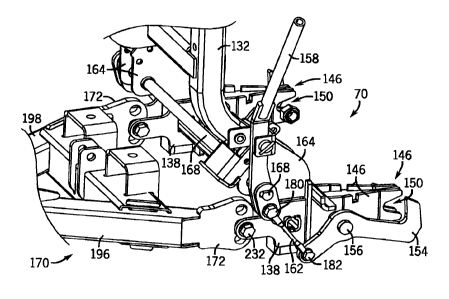
[0044] Fig. 3 illustrates an exemplary embodiment
of a quick connect/disconnect hitch 70 assembly. The
hitch frame nose assembly 100 is coupled to a vehicle
chassis 60. Coupled to the hitch frame nose
assembly 100 is the lift bar assembly 130 which in
turn is coupled to a plow frame 170.
[0045] The lift bar assembly 130 includes a pair of
lift bar support members 132 maintained in a spaced
apart relationship and coupled to a lift bar
approximate the top of each lift bar support member
132. A light bar brace 136 approximate the lower end
of each lift bar support member 132 facilitates
maintenance of the spaced apart relationship of the
REINHART\2501853JAW:KAB 10/15/08 10
CA 02669270 2009-06-17
lift bar support member 132. A pair of lift bar lugs
138 are coupled to each lift bar support member 132
approximate the light bar brace 136. (Also see Figs.
12 and 12a). Coupled to the lift bar 134 are a pair
of upper lift cylinder mounts 140 configured to
operably secure a power mechanism, for example a lift
cylinder 142. Also coupled to the lift bar assembly
130 is a locking mechanism 144.
[0046] Referring to Fig. 4, there is illustrated a
hitch frame nose assembly 100 coupled to a vehicle
chassis 60 and positioned to receive a locking
mechanism 144 of a quick connect/disconnect hitch 70.
The locking mechanism 144 includes a pair of notched
members 146 coupled to the lift bar assembly 130 and
positioned to correspond for engagement with each of
the chassis couplers 108 of the hitch frame nose
assembly 100.
[0047] Each notch member 146 includes a pair of
tapered side members 148 with each tapered side
member 148 defining a notch 150. Each notch 150 is
configured to engage the traverse pin 124 positioned
between the two sides 114 of each chassis coupler 108.
Each notch member 146 also includes a plate member 152
fastened to the top portion of each of the tapered
side members 148, typically by welding a plate
member 150 to each tapered side member 148. The plate
member provides additional reinforcement for the notch
member 146 and defines with the two tapered side
members 148 an inverted U-shape assembly. With the
notch member 146 engaged with the chassis coupler 108
the pivot for the quick connect/disconnect hitch 70
formed by the engagement of the notch 150 with the
traverse pin 124 is enclosed within the two facing u-
shaped assemblies.
REINHART\2501653JAW:KAB 10/15/08 11
CA 02669270 2009-06-17
[0048] Each notched member 146 further includes a
locking hook 154 pivotally coupled to a hook pivot
156. The hook pivot 156 extends through each of the
tapered side members 148 of each notch member 146.
The locking hook 154 moves about the hook pivot 156 in
response to movement of the hitch locking lever 158 as
the hitch locking lever 158 moves about a lever pivot
160. The hitch locking lever 158 is coupled to the
locking hook 154 by a lock linkage 162. The operation
of the locking mechanism 144 will be explained below.
[0049] The orientation of the locking hook 154 and
the notch member 146 is such that when the notch
member 146 is inserted into the chassis coupler 108
the locking hook is positioned outside of the u-shaped
chassis coupler 108 and positioned to selectively
engage the portion 128 of the traverse pin 124 that
extends beyond the side 114 of the chassis
coupler 108. It should be understood that there is a
locking hook 154 on each of the notch members 146
which engages the traverse pin 124 extending beyond
the side 114 of each of the chassis couplers 108 that
are part of the hitch frame nose assembly 100. The
locking hook 154 locks the lift bar assembly 130 to
the hitch frame nose assembly 100.
[0050] Locking mechanism 144 also includes a lock
support bracket 164 which is coupled to each of the
lift bar support members 132. A preferred embodiment
provides that a pair of lock support brackets 164 are
coupled to each side of the corresponding lift bar
support member 132. (Figs. 3 and 4). It should be
understood that the locking mechanism 144 includes a
locking hook 154, hook pivot 156, lock linkage 162 on
each outward side of the lift bar assembly 130. On
one side of the lift bar assembly 130, the hitch
REINHART\2501653JAW:KAP 10/15/08 12
, CA 02669270 2009-06-17 ,
locking lever 158 is coupled to the linkage, and on
the other side of the lift bar assembly 130 the lock
linkage 162 is coupled to a lock linkage bracket 166.
(See Fig. 9). The lock linkage bracket 166 and the
hitch locking lever 158 are coupled together by a
hitch lock extension rod 168 extending through each of
the lock support brackets 164 and each of the lift bar
support members 132. The hitch lock lever 158 and the
lock linkage bracket 166 are journaled to the hitch
lock extension rod 168 by a flat face defined on each
end of the hitch lock extension rod 168. (See Figs. 8
and 9).
[0051] The operation of coupling the quick
connect/disconnect hitch 70 to the vehicle chassis 60
will now be described with reference to Figs. 5
through 9. Fig. 5 illustrates an exemplary embodiment
of a quick connect/disconnect hitch 70 positioned to
engage the hitch frame nose assembly 100 coupled to a
vehicle chassis 60. The hitch locking lever 158 is in
an unlocked position 174. The movement of the hitch
lock lever 158 to the unlocked position 174 rotated
the locking hook as illustrated in Fig. 5. The
vehicle having a hitch frame nose assembly 100 coupled
to the vehicle chassis 60 is moved towards the quick
connect/disconnect hitch 70 as indicated by the arrow
in Fig. 5.
[0052] Fig. 6 illustrates the quick
connect/disconnect hitch 70 engaged with the hitch
frame nose assembly 100 with each notched member 146
of the lift bar assembly 130 coupled to the traverse
pin 124 in each of the chassis couplers 108. Such
engagement is illustrated at least in Figs. 10 and 11.
In this position, with the hitch locking lever 158
still in the unlocked position 174 the vehicle can be
REINHART\2501853JAW:KAB 10/15/08 13
CA 02669270 2009-06-17
moved away from the hitch 70 if additional adjustment
maneuvers are necessary.
[0053] Fig. 7 illustrates the locking mechanism 144
in a first locked position 176. In the first locked
position 176, the locking hook has moved to engage the
traverse pin 124 in each of the chassis couplers 108.
In this configuration, the lever pivot 160, the hitch
locking lever linkage attachment 180 and the hook
linkage attachment 182 are substantially in a straight
line as illustrated in Fig. 7.
[0054] To complete the locking maneuver of the
locking mechanism 144, the hitch locking lever 158 is
moved to a second locked position 178 which forces the
hitch locking lever 158 to move over center of the
lever pivot 160 as illustrated in Fig. 8. The hitch
locking lever 158 also is secured in a retaining
bracket 184 coupled to a locked support bracket 164.
The retaining bracket 184 includes a retaining pin 186
which is biased by a spring 188. The retaining pin
186 engages an orifice defined in the hitch lever
locking lever 158 as illustrated in Fig. 3A. It
should be understood that other ways of securing the
locking lever 158 can be used to prevent the locking
lever 158 from inadvertently unlocking the hitch 70.
[0055] As described above, the locking mechanism
144 includes a lock hook 154 on each side of the lift
bar assembly 130 and are coupled together to
simultaneously operate with movement of the hitch
locking lever 158. Fig. 9 illustrates the other side
of the locking mechanism 144 illustrated in Fig. 8.
[0056] The lift bar assembly 130 is coupled to a
plow frame 170. The lift bar assembly 130 is provided
with a pair of lift bar lugs 138 coupled to the lift
bar brace 136 and to each of the lock support
REINHART\2501653JAW:KAB 10/15/08 14
CA 02669270 2009-06-17
brackets 164 on both sides of the lift bar assembly
130 (see Fig. 12).
[0057] A plow frame 170 is configured substantially
in the form of a letter A with the plow frame 170
including a front portion 175 and a rear portion 177.
The plow frame 170 includes two side members 196, 198
which form the sides of the A-shape with a traverse
brace tube 200 coupled to each of the side members
196, 198. The side members 196, 198 and the traverse
brace tube 200 are conventional steel square tubing,
however, it is contemplated that other cross-section
configured tubes, for example circular or triangular,
can be used. Coupled to the front portion 175 of the
plow frame 170 is a swing frame pivot assembly 185.
The swing frame pivot assembly includes a top plate
187 and a bottom plate 189. Each of the plates 187,
189 defines an orifice configured to receive a swing
frame pivot pin 190. The swing frame pivot assembly
185 is further coupled to each of the side members
196, 198 of the plow frame 170 by a pair of side
support brackets 192, 194 which are configured to
couple to each of the top plate 187, the bottom plate
189 and one of the side members of the plow frame 170.
[0058] In one embodiment, a portion of the top
plate 187 is bent downwardly at a 90 degree angle to
extend the top plate 187 to the bottom plate 189 with
that portion of the top plate configured to define an
angled pocket to receive each of the side members 196,
198 of the plow frame 170. See Figs. 13 and 14.
[0059] Coupled to the traverse brace tube 200 are
lift cylinder mounts 206 and a pair of swing cylinder
mounts 202 and 204. Lift cylinder mounts 206 are
aligned to couple the lower end of the lift cylinder
1EINHART\2501653jAW:KAB 10/15/08 15
CA 02669270 2009-06-17 - -
142 which is coupled to the upper lift cylinder mount
140 on the lift bar 134.
[0060] Each of the side members 196, 198 of the
plow frame 170 include an adjustment lug 172 at the
rear portion 177 of the plow frame 170. Each
adjustment lug 172 includes a plurality of orifices
179 aligned vertically and configured to receive a
bolt 232 which will couple the plow frame 170 to the
lift bar lugs 138 on the lift bar assembly 130. As
best seen in Figs. 12, 12A, 12B, and 12C, the
adjustment lug 172 is received between each of the
lift bar lugs 138 of the lift bar assembly 130 and
secured with a bolt 232. In order to adjust the plow
frame height relative to the vehicle, an operator will
select one of the vertical adjustment orifices 179 to
properly align the plow frame 170 with the lift bar
assembly 130 which is in turn coupled with the chassis
couplers 108 of the hitch frame nose assembly 100.
[0061] A swing frame 208 is pivotally coupled to
the swing frame pivot assembly 184 of the plow frame
170 (see at least Figs. 15 and 18). The swing frame
208 includes a swing frame tube 209 which has two
swing frame ends 210 and 212. Coupled to each swing
frame end 210, 212 is a pair of trip spring brackets
220. (See Figs. 15 and 17.) Each trip spring bracket
220 includes a trip spring mount 224, a cushion trip
plate 280 and a blade pivot mount 226. Each pair of
trip spring brackets 220 are coupled to the swing
frame tube 209, for example by welding.
[0062] The swing frame 208 includes a pivot 230
positioned in a center portion 214 of the swing frame
tube 208. The pivot 230 couples to the swing frame
pivot assembly 184 of the plow frame 170 with the
swing frame pivot pin 190.
REINHART\2501653JAW:KAB 10/15/08 16
CA 02669270 2009-06-17
[0063] The swing frame tube 109 also supports a
pair of swing cylinder mounts 236 mounted on the swing
frame tube 209 with each swing cylinder mount 236
positioned between the center portion 214 of the swing
frame tube 209 and one end 210, 212 of the swing frame
tube 209. (See Fig. 15.) A swing cylinder 252 is
coupled at one end to a swing cylinder mount 236 on
the swing frame 208 and on another end on the swing
cylinders mounts 202, 204 of the plow frame 170. The
swing cylinder 252 as selectively operated by a user
of the snow plow 50 can rotate the plow blade 250
about the pivot 230. The degree of rotation of the
plow blade relative to the plow frame 170 is
established by the extension capabilities of the swing
cylinders 252 as selected by an operator.
[0064] The plow blade 250 is coupled to the swing
frame 208 pinning the plow blade to each of the trip
spring brackets 240 at the blade pivot mount 226 on
each of the trip spring brackets 220. A pivot pin is
received in a pivot aperture 234 and is typically
secured in place by a cotter pin (not shown). It is
contemplated that other means of fastening the pivot
pin can be used such as a bolt and nut.
[0065] Also coupled to the trip spring bracket 220
is a cushion trip plate 280. The cushion trip plate
280 is configured with a pair of oversize bolt
apertures 240 to accommodate a socket or other tool
for manipulating a cushion bolt 238 to secure a
cushion block 228 to the cushion mount 222. The
cushion block 228 is substantially a rectangular
shaped block of polyurethane or other high density
resilient material. The cushion block 228 is used to
absorb the impact of the plow blade 250 (see Figs. 23A
and 23B) as the plow blade moves between its limits.
REINHART\2501653JAW:KAB 10/15/08 17
CA 02669270 2009-06-17
Such movement of the plow blade 250 is caused by the
plow blade 250 striking an object as the plow blade
250 is moved by a vehicle. The cushion block 228 is
configured to prevent damage to the snow plow by
allowing the snow plow blade 250 to "trip" that is,
for the bottom of the plow blade 250 to move rearward
and the top of the plow blade 250 to simultaneously
move forward about the blade pivot pin, resulting in a
rotation of plow blade 250 around a horizontal axis.
Such a rotation is inhibited by springs 284 which act
as a shock absorber mechanism, and which return the
plow blade 250 to a normal or "trip return" position.
The springs 284 are relatively strong, since they must
prevent the plow blade from rotating when it is
plowing snow and the metal-to-metal impacts of both a
plow trip bracket and a blade trip return can be
substantial. The cushion block 228 is configured to
cushion the impacts on both the blade and the trip
spring bracket 220.
[0066] It is also contemplated that a back cushion
(not shown) similar to the cushion block 228 can be
coupled, for example by bolting, to a blade stop 282
at a lower end of each of the trip spring brackets
220. The back cushion is configured to ameliorate
vibration and damage to the plow blade 250 if the plow
blade contacts an obstruction during operation.
[0067] The cushion block 228 is rectangular in
shape and provides a relatively large area to
distribute the force exerted upon the cushion block
228 when the blade 250 moves back to its trip return
position by action of the return springs 284. The
relatively large cushion bolt aperture 240 allows a
user to easily access the cushion bolts 238 when
servicing the cushion block. Servicing of the cushion
REINHART\2501653JAW:KAB 10/15/08 18
CA 02669270 2009-06-17
block 228 can be accomplished, for example, replacing
the cushion block without having to remove the plow
blade 250 from the swing frame 208. However, a slight
forward rotation of the blade 250 must be provided to
remove the cushion block from between the cushion
mount 222 and the cushion trip plate 280.
[0068] Referring now to Figs. 18, 19, 20 and 21,
Fig. 18 illustrates a snow plow 50 with a plow blade
assembly 260 coupled to a quick connect/disconnect
hitch 70. Fig. 18 is a bottom, rear isometric view of
the snow plow 50.
[0069] Fig. 19 is an exploded view of the plow
blade assembly 260. The plow blade 250, is coupled,
for example, by welding, to a plurality of plow ribs
268. Each of the plow ribs 268 are aligned vertically
and coupled to a bottom plow frame member 262. The
plow ribs 268 are positioned at evenly spaced
intervals along the bottom plow frame member 262 and
welded to the plow blade 250 and the bottom plow frame
member 262. Each of the plow ribs 268 is configured
in a concave curve to which the plow blade 250
conforms and which also facilitates movement of
material such as snow as the plow 50 is operated. A
wear strip 270 is coupled to the lower edge of the
plow blade 250 by a plurality of bolts 272 which
extend through the wear strip 270, the plow blade 250,
the bottom plow frame member 262 and a nut plate 274
which is positioned against one of the downward
extending flanges of the bottom plow frame member 262.
(See at least Fig. 20.) Reinforcement members 264 are
positioned between the down facing flanges of the
bottom plow frame member to reinforce the plow blade
assembly 260. The reinforcement members 264 are
typically welded to the bottom plow frame member 262.
REINHART\2501653JAW:KAB 10/15/08 19
CA 02669270 2009-06-17
The top edge of the plow blade 250 is bent and
configured to be coupled to the top edge of each of
the plow ribs 268. The top edge of the plow blade 250
is typically welded to each of the plow ribs 268.
[0070] Referring to Fig. 20, a pair of plow trip
spring brackets 276 are coupled, for example, by
welding, each to two of a plow rib 268. The plow trip
spring brackets 276 are aligned with the spring mounts
224 on each of the spring brackets 220 coupled to the
swing frame 208. A cushion mount 222 is also coupled,
typically by welding, to each of the plow ribs 268
that support the plow trip spring brackets 276. A
cushion block 228 is bolted to each of the cushion
mounts 222 and are configured and aligned to contact a
cushion trip plate 280 coupled to each of the trip
spring brackets 220.
[0071] As illustrated in Fig. 24, a plurality of
trip springs 284 are coupled to each of the plow trip
spring brackets 276 and the trip spring brackets 220.
Fig. 24 also illustrates a light bar 286 coupled to
the lift bar support brackets 132. The light bar 286
supports a plurality of light brackets 288 to which
plow lights (not shown) are coupled. Plow lights are
typically needed since the snow plow 50 typically
obstructs the headlights of the vehicle to which the
snow plow 50 is coupled.
[0072] For purposes of this disclosure, the term
"coupled" means the joining of two components
(electrical or mechanical) directly or indirectly to
one another. Such joining may be stationary in nature
or moveable in nature. Such joining may be achieved
with the two components (electrical or mechanical) and
any additional intermediate members being integrally
formed as a single unitary body with one another or
REINHART\25131653JAw:Km 10/15/08 20
CA 02669270 2009-06-17
the two components and any additional member being
attached to one another. Such adjoining may be
permanent in nature or alternatively be removable or
releasable in nature.
[0073] Although the foregoing description of a
quick connect/disconnect hitch has been shown and
described with reference to particular embodiments and
applications thereof, it has been presented for
purposes of illustration and description and is not
intended to be exhaustive or to limit the invention to
the particular embodiments and applications disclosed.
It will be apparent to those having ordinary skill in
the art that a number of changes, modifications,
variations, or alterations to the hitch as described
herein may be made, none of which depart from the
spirit or scope of the present invention. The
particular embodiments and applications were chosen
and described to provide the best illustration of the
principles of the invention and its practical
application to thereby enable one of ordinary skill in
the art to utilize the invention in various
embodiments and with various modifications as are
suited to the particular use contemplated. All such
changes, modifications, variations, and alterations
should therefore be seen as being within the scope of
the present invention as determined by the appended
claims when interpreted in accordance with the breadth
to which they are fairly, legally, and equitably
entitled.
REINHART\2501653JAW:KAB 10/15/08 21