Language selection

Search

Patent 2669331 Summary

Third-party information liability

Some of the information on this Web page has been provided by external sources. The Government of Canada is not responsible for the accuracy, reliability or currency of the information supplied by external sources. Users wishing to rely upon this information should consult directly with the source of the information. Content provided by external sources is not subject to official languages, privacy and accessibility requirements.

Claims and Abstract availability

Any discrepancies in the text and image of the Claims and Abstract are due to differing posting times. Text of the Claims and Abstract are posted:

  • At the time the application is open to public inspection;
  • At the time of issue of the patent (grant).
(12) Patent Application: (11) CA 2669331
(54) English Title: MOULDED PANEL JOINT CAULKING MEANS
(54) French Title: MOYEN DE GARNITURE DE JOINT POUR PANNEAU MOULE
Status: Deemed Abandoned and Beyond the Period of Reinstatement - Pending Response to Notice of Disregarded Communication
Bibliographic Data
(51) International Patent Classification (IPC):
  • E01C 11/10 (2006.01)
  • E04B 01/684 (2006.01)
  • E04F 21/165 (2006.01)
(72) Inventors :
  • SLADOJEVIC, ROBERT (Australia)
(73) Owners :
  • SRB CONSTRUCTION TECHNOLOGIES PTY LTD
(71) Applicants :
  • SRB CONSTRUCTION TECHNOLOGIES PTY LTD (Australia)
(74) Agent: SMART & BIGGAR LP
(74) Associate agent:
(45) Issued:
(86) PCT Filing Date: 2007-10-31
(87) Open to Public Inspection: 2008-05-22
Availability of licence: N/A
Dedicated to the Public: N/A
(25) Language of filing: English

Patent Cooperation Treaty (PCT): Yes
(86) PCT Filing Number: PCT/AU2007/001653
(87) International Publication Number: AU2007001653
(85) National Entry: 2009-05-13

(30) Application Priority Data:
Application No. Country/Territory Date
2006906338 (Australia) 2006-11-14

Abstracts

English Abstract

A caulking strip (15) for caulking a joint between components includes an elongate body member defining a head portion (17) and a stem portion (18) extending from the head portion (17) to be received between the two components. A plurality of engaging formations (19, 20, 21), at least some of which are of a resiliently flexible material, project laterally from the stem portion (18) to abut substantially sealingly against facing sides of the components between which the body member is received.


French Abstract

Une bande de garniture (15) destinée à garnir un joint situé entre des composants comprend un élément de corps allongé définissant une partie de tête (17) et une partie de tige (18) s'étendant depuis la partie de tête (17) reçue entre les deux composants. Plusieurs profils d'emboîtement (19, 20, 21) dont au moins certains sont dans un matériau flexible élastiquement, ressortent latéralement de la partie de tige (18) et sont sensiblement adjacentes de manière étanche aux côtés opposés des composants entre lesquels l'élément de corps vient se loger.

Claims

Note: Claims are shown in the official language in which they were submitted.

CLAIMS:
1. A caulking strip for caulking a joint between components, the strip
including
an elongate body member defining a head portion and a stem portion extending
from the head portion to be received between the two components; and
a plurality of engaging formations, at least some of which are of a
resiliently
flexible material, projecting laterally from the stem portion to abut
substantially
sealingly against facing sides of the components between which the body member
is
received.
2. The strip of claim 1 in which the body member is a one-piece unit of a
resiliently flexible material.
3. The strip of claim 1 or claim 2 in which the stem portion is bifurcated to
form at
least two limbs, each limb carrying an array of the projections, at least one
of the
projections extending laterally further than the remaining projections.
4. The strip of any one of the preceding claims in which the head portion
defines
abutment surfaces which abut against the components, the abutment surfaces
being
arranged on opposite sides of the stem portion.
5. A panel system which includes
a pair of panels arranged in aligned spaced relationship to define a gap
between
facing sides of the panel;
at least one caulking strip, as claimed in any one of the preceding claims,
received in the gap to form a caulked joint.
6. The system of claim 5 which includes a pair of the caulking strips, the
strips
being arranged in facing relationship at opposed ends of the gaps.
7. The system of claim 5 or claim 6 in which an edge of each panel is shaped
to
accommodate a part of the head portion of the body member of the at least one
caulking strip.
8. The system of any one of claims 5 to 7 in which the facing side of each
panel
defines a receiving zone to receive at least one of the engaging formations of
the
caulking strip.

6
9. The system of any one of claims 5 to 8 in which a fire-retardant material
is
received in each caulking strip.

Description

Note: Descriptions are shown in the official language in which they were submitted.


CA 02669331 2009-05-13
WO 2008/058311 PCT/AU2007/001653
1
"Moulded panel joint caulking means"
Cross-Reference to Related Applications
The present application claims priority from Australian Provisional Patent
Application No 2006906338 filed on 14 November 2006, the contents of which are
incorporated herein by reference.
Field of the Invention
This invention relates, generally, to the caulking of joints, and more
particularly
to a caulking strip for caulking of joints between construction panels. The
panels are
preferably moulded concrete panels, more particularly, tilt-up panels which
are poured
on site and, once set, raised and located in position. The invention relates
also to a
panel system.
Background to the Invention
At present, tilt-up building construction panels are caulked using a caulking
infill compound which is pumped into the panel joints after they are erected.
This
procedure is very expensive and time consuming and must normally be carried
out by a
specialised tradesperson. A further disadvantage is that the caulking compound
or
material undergoes shrinkage as it dries and this can affect its ability to
seal the joint
effectively and make it weather-proof. This problem often requires that panel
joints be
re-caulked at a later date which in turn creates additional cost and
inconvenience.
Summary of the Invention
According to a first aspect of the invention, there is provided a caulking
strip for
caulking a joint between components, the strip including
an elongate body member defining a head portion and a stem portion extending
from the head portion to be received between the two components; and
a plurality of engaging formations, at least some of which are of a
resiliently
flexible material, projecting laterally from the stem portion to abut
substantially
sealingly against facing sides of the components between which the body member
is
received.
The body member may be a one-piece unit of a resiliently flexible material.
The stem portion may be bifurcated to form at least two limbs, each limb
carrying an array of the projections, at least one of the projections
extending laterally
further than the remaining projections. It will be appreciated that the limbs
are mirror

CA 02669331 2009-05-13
WO 2008/058311 PCT/AU2007/001653
2
images of each other. The head portion may define abutment surfaces which abut
against the components, the abutment surfaces being arranged on opposite sides
of the
stem portion.
According to second aspect of the invention, there is provided a panel system
which includes
a pair of panels arranged in aligned spaced relationship to define a gap
between
facing sides of the panel;
at least one caulking strip, as described above, received in the gap to form a
caulked joint.
Preferably, the system includes a pair of the caulking strips, the strips
being
arranged in facing relationship at opposed ends of the gaps.
An edge of each panel may be shaped to accommodate a part of the head portion
of the body member of the at least one caulking strip. The facing side of each
panel
may define a receiving zone to receive at least one of the engaging formations
of the
caulking strip.
A fire-retardant material may be received in each caulking strip. More
particularly, the fire retardant material may be received in a slot defined
between the
limbs of the stem portion of the caulking strip.
Brief Description of the Drawinlls
An embodiment of the invention is now described by way of example with
reference to the accompanying drawings in which:-
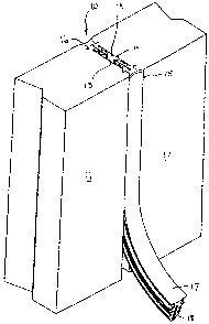
Fig. 1 is a fragmentary exploded perspective view of a caulked panel system in
accordance with an embodiment of the invention;
Fig. 2 is a cross-sectional plan view taken through the panel system shown in
Fig. 1; and
Fig. 3 is a plan view of an embodiment of a caulking strip used to caulk the
panel joint shown in Fig. 1.
Detailed Description of Exemplary Embodiment
In Figs. 1 and 2 of the drawings, reference numeral 10 generally designates an
embodiment of a panel system. The panel system 10 comprises a pair of concrete
building panels 11, 12 which are arranged in aligned spaced relationship with
their
facing sides 13, 14, respectively, forming a gap 30.
In this embodiment, the gap 30 between the facing sides 13, 14 of the panels
11,
12 respectively, is caulked by means of two elongate caulking strips 15, 16,
also in

CA 02669331 2009-05-13
WO 2008/058311 PCT/AU2007/001653
3
accordance with an embodiment of the invention, inserted in opposite ends of
the gap
30.
Referring now to Fig. 3 of the drawings one of the caulking strips 15 is
described in greater detail. It will be appreciated that the other caulking
strip 16 is
identical. The caulking strip 15 is approximately T-shaped in cross-section
and has a
head portion 17 and a stem portion 18 projecting centrally from one side of
the head
portion 17.
The stem portion 18 carries laterally projecting engaging formations in the
form
of ribs 19, 20, 21, the purpose of which will be described below. The stem
portion 18
is bifurcated and is formed to have spaced axially extending limbs 18', 18"
which are
separated by an open-ended slot 22. The slot 22 allows the leg portions 18'
18" to be
squeezed together so as to compress the stem portion 18 when it is inserted
into the gap
30 between the panels 11, 12. The limbs 18', 18" are mirror images of each
other and
each limb 18', 18" carries an array of the ribs 19, 20, 21.
Each of the ribs 19, 20, 21 is approximately saw-tooth shaped in vertical
cross-
section having a tapered leading end and a blunt trailing end. The rib 19 has
a lateral
dimension greater than that of each of the other ribs 20, 21.
The head portion 17 of the strip 15, 16 has a concave outer face 25 and a
tapered
inner face 26 from which the stem portion 18 projects. The inner face 26
defines a pair
of abutment surfaces 32, the surfaces 32 being arranged on opposed sides of
the stem
portion 18.
As shown in Fig. 2 of the drawings, each of the facing sides 13, 14 of the
panels
11, 12 has moulded therein a pair of spaced, parallel longitudinally extending
grooves
28. Each groove 28 is shaped approximately complementarily to the shape of an
associated rib 19 of each strip 15, 16. Thus, when the strips 15, 16 are fully
inserted in
position, the ribs 19 are received in a locking manner in their associated
grooves 28.
Each edge 34 (Fig. 2) of the facing sides 13, 14 of the panels 11, 12 is
bevelled
so as to form a bearing surface against which one of the abutment surfaces 32
if the
head portion of the relevant strip 15, 16 abuts in a substantially sealing
manner. The
head portion 17 thus lies substantially flush with surfaces of adjacent panels
11, 12. In
this embodiment, with the concave outer face 25 of the head portion of each
strip 15,
16, a shallow recess extends longitudinally along the join.
When the strips 15, 16 are fully inserted into the gap 30, the ribs 20, 21 are
slightly deformed (as can be seen in Fig. 2) and make tight frictional
engagement with
the sides 13, 14 of the panels 11, 12. It will of course be appreciated that
the ribs 19
will similarly deform but once they align with their associated
complementarily shaped

CA 02669331 2009-05-13
WO 2008/058311 PCT/AU2007/001653
4
grooves 28, they spring outwardly and lockably engage with their associated
grooves
28. The sealing contact made between the outer surfaces of the stem portion 18
of each
strip 15, 16 and the sides 13, 14 of the panels 11, 12 is effective to render
the joint so
formed weather-proof. It will be appreciated that each strip 15, 16 is formed
of a
resiliently flexible material, more particularly, an elastomeric material such
as a
suitable rubber or rubber like material. This enhances the sealing action of
each strip
15, 16.
If desired, the slot 22 of each strip 15, 16 is filled with a fire retardant
material
to increase the fire proof rating of the panel system 10.
It will be appreciated that the panel system 10 may be used to caulk panel
joints
for any type of concrete panel construction, e.g. large concrete water tanks.
It is an advantage of the present invention that the shape and dimensions of
the
strips 15, 16 inhibits shrinkage when inserted into the joint 30. It is
another advantage
that, in the event of a strip 15, 16 being damaged, it can be readily removed
and
replaced with a new strip 15, 16.
It will be appreciated by persons skilled in the art that numerous variations
and/or modifications may be made to the invention as shown in the specific
embodiments without departing from the spirit or scope of the invention as
broadly
described. The present embodiments are, therefore, to be considered in all
respects as
illustrative and not restrictive.

Representative Drawing
A single figure which represents the drawing illustrating the invention.
Administrative Status

2024-08-01:As part of the Next Generation Patents (NGP) transition, the Canadian Patents Database (CPD) now contains a more detailed Event History, which replicates the Event Log of our new back-office solution.

Please note that "Inactive:" events refers to events no longer in use in our new back-office solution.

For a clearer understanding of the status of the application/patent presented on this page, the site Disclaimer , as well as the definitions for Patent , Event History , Maintenance Fee  and Payment History  should be consulted.

Event History

Description Date
Application Not Reinstated by Deadline 2013-10-31
Time Limit for Reversal Expired 2013-10-31
Inactive: Abandon-RFE+Late fee unpaid-Correspondence sent 2012-10-31
Deemed Abandoned - Failure to Respond to Maintenance Fee Notice 2012-10-31
Reinstatement Requirements Deemed Compliant for All Abandonment Reasons 2012-01-05
Letter Sent 2012-01-05
Inactive: Office letter 2011-12-06
Deemed Abandoned - Failure to Respond to Maintenance Fee Notice 2011-10-31
Inactive: Cover page published 2009-08-21
Inactive: Notice - National entry - No RFE 2009-07-23
Inactive: First IPC assigned 2009-07-09
Application Received - PCT 2009-07-08
National Entry Requirements Determined Compliant 2009-05-13
Application Published (Open to Public Inspection) 2008-05-22

Abandonment History

Abandonment Date Reason Reinstatement Date
2012-10-31
2011-10-31

Maintenance Fee

The last payment was received on 2012-01-05

Note : If the full payment has not been received on or before the date indicated, a further fee may be required which may be one of the following

  • the reinstatement fee;
  • the late payment fee; or
  • additional fee to reverse deemed expiry.

Patent fees are adjusted on the 1st of January every year. The amounts above are the current amounts if received by December 31 of the current year.
Please refer to the CIPO Patent Fees web page to see all current fee amounts.

Fee History

Fee Type Anniversary Year Due Date Paid Date
Basic national fee - standard 2009-05-13
MF (application, 2nd anniv.) - standard 02 2009-11-02 2009-05-13
MF (application, 3rd anniv.) - standard 03 2010-11-01 2010-10-29
MF (application, 4th anniv.) - standard 04 2011-10-31 2012-01-05
Reinstatement 2012-01-05
Owners on Record

Note: Records showing the ownership history in alphabetical order.

Current Owners on Record
SRB CONSTRUCTION TECHNOLOGIES PTY LTD
Past Owners on Record
ROBERT SLADOJEVIC
Past Owners that do not appear in the "Owners on Record" listing will appear in other documentation within the application.
Documents

To view selected files, please enter reCAPTCHA code :


To view images, click a link in the Document Description column. To download the documents, select one or more checkboxes in the first column and then click the "Download Selected in PDF format (Zip Archive)" or the "Download Selected as Single PDF" button.

List of published and non-published patent-specific documents on the CPD .

If you have any difficulty accessing content, you can call the Client Service Centre at 1-866-997-1936 or send them an e-mail at CIPO Client Service Centre.


Document
Description 
Date
(yyyy-mm-dd) 
Number of pages   Size of Image (KB) 
Description 2009-05-12 4 207
Drawings 2009-05-12 3 34
Claims 2009-05-12 2 49
Abstract 2009-05-12 2 60
Representative drawing 2009-07-23 1 5
Notice of National Entry 2009-07-22 1 192
Courtesy - Abandonment Letter (Maintenance Fee) 2011-12-27 1 172
Notice of Reinstatement 2012-01-04 1 164
Reminder - Request for Examination 2012-07-03 1 125
Courtesy - Abandonment Letter (Maintenance Fee) 2012-12-26 1 174
Courtesy - Abandonment Letter (Request for Examination) 2013-02-05 1 164
PCT 2009-05-12 3 98
PCT 2010-06-22 1 43
PCT 2010-07-20 1 46
Correspondence 2011-12-05 1 19
Correspondence 2011-11-13 38 1,369