Sélection de la langue

Search

Sommaire du brevet 2669331 

Énoncé de désistement de responsabilité concernant l'information provenant de tiers

Une partie des informations de ce site Web a été fournie par des sources externes. Le gouvernement du Canada n'assume aucune responsabilité concernant la précision, l'actualité ou la fiabilité des informations fournies par les sources externes. Les utilisateurs qui désirent employer cette information devraient consulter directement la source des informations. Le contenu fourni par les sources externes n'est pas assujetti aux exigences sur les langues officielles, la protection des renseignements personnels et l'accessibilité.

Disponibilité de l'Abrégé et des Revendications

L'apparition de différences dans le texte et l'image des Revendications et de l'Abrégé dépend du moment auquel le document est publié. Les textes des Revendications et de l'Abrégé sont affichés :

  • lorsque la demande peut être examinée par le public;
  • lorsque le brevet est émis (délivrance).
(12) Demande de brevet: (11) CA 2669331
(54) Titre français: MOYEN DE GARNITURE DE JOINT POUR PANNEAU MOULE
(54) Titre anglais: MOULDED PANEL JOINT CAULKING MEANS
Statut: Réputée abandonnée et au-delà du délai pour le rétablissement - en attente de la réponse à l’avis de communication rejetée
Données bibliographiques
(51) Classification internationale des brevets (CIB):
  • E01C 11/10 (2006.01)
  • E04B 01/684 (2006.01)
  • E04F 21/165 (2006.01)
(72) Inventeurs :
  • SLADOJEVIC, ROBERT (Australie)
(73) Titulaires :
  • SRB CONSTRUCTION TECHNOLOGIES PTY LTD
(71) Demandeurs :
  • SRB CONSTRUCTION TECHNOLOGIES PTY LTD (Australie)
(74) Agent: SMART & BIGGAR LP
(74) Co-agent:
(45) Délivré:
(86) Date de dépôt PCT: 2007-10-31
(87) Mise à la disponibilité du public: 2008-05-22
Licence disponible: S.O.
Cédé au domaine public: S.O.
(25) Langue des documents déposés: Anglais

Traité de coopération en matière de brevets (PCT): Oui
(86) Numéro de la demande PCT: PCT/AU2007/001653
(87) Numéro de publication internationale PCT: AU2007001653
(85) Entrée nationale: 2009-05-13

(30) Données de priorité de la demande:
Numéro de la demande Pays / territoire Date
2006906338 (Australie) 2006-11-14

Abrégés

Abrégé français

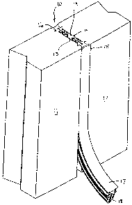
Une bande de garniture (15) destinée à garnir un joint situé entre des composants comprend un élément de corps allongé définissant une partie de tête (17) et une partie de tige (18) s'étendant depuis la partie de tête (17) reçue entre les deux composants. Plusieurs profils d'emboîtement (19, 20, 21) dont au moins certains sont dans un matériau flexible élastiquement, ressortent latéralement de la partie de tige (18) et sont sensiblement adjacentes de manière étanche aux côtés opposés des composants entre lesquels l'élément de corps vient se loger.


Abrégé anglais

A caulking strip (15) for caulking a joint between components includes an elongate body member defining a head portion (17) and a stem portion (18) extending from the head portion (17) to be received between the two components. A plurality of engaging formations (19, 20, 21), at least some of which are of a resiliently flexible material, project laterally from the stem portion (18) to abut substantially sealingly against facing sides of the components between which the body member is received.

Revendications

Note : Les revendications sont présentées dans la langue officielle dans laquelle elles ont été soumises.


CLAIMS:
1. A caulking strip for caulking a joint between components, the strip
including
an elongate body member defining a head portion and a stem portion extending
from the head portion to be received between the two components; and
a plurality of engaging formations, at least some of which are of a
resiliently
flexible material, projecting laterally from the stem portion to abut
substantially
sealingly against facing sides of the components between which the body member
is
received.
2. The strip of claim 1 in which the body member is a one-piece unit of a
resiliently flexible material.
3. The strip of claim 1 or claim 2 in which the stem portion is bifurcated to
form at
least two limbs, each limb carrying an array of the projections, at least one
of the
projections extending laterally further than the remaining projections.
4. The strip of any one of the preceding claims in which the head portion
defines
abutment surfaces which abut against the components, the abutment surfaces
being
arranged on opposite sides of the stem portion.
5. A panel system which includes
a pair of panels arranged in aligned spaced relationship to define a gap
between
facing sides of the panel;
at least one caulking strip, as claimed in any one of the preceding claims,
received in the gap to form a caulked joint.
6. The system of claim 5 which includes a pair of the caulking strips, the
strips
being arranged in facing relationship at opposed ends of the gaps.
7. The system of claim 5 or claim 6 in which an edge of each panel is shaped
to
accommodate a part of the head portion of the body member of the at least one
caulking strip.
8. The system of any one of claims 5 to 7 in which the facing side of each
panel
defines a receiving zone to receive at least one of the engaging formations of
the
caulking strip.

6
9. The system of any one of claims 5 to 8 in which a fire-retardant material
is
received in each caulking strip.

Description

Note : Les descriptions sont présentées dans la langue officielle dans laquelle elles ont été soumises.


CA 02669331 2009-05-13
WO 2008/058311 PCT/AU2007/001653
1
"Moulded panel joint caulking means"
Cross-Reference to Related Applications
The present application claims priority from Australian Provisional Patent
Application No 2006906338 filed on 14 November 2006, the contents of which are
incorporated herein by reference.
Field of the Invention
This invention relates, generally, to the caulking of joints, and more
particularly
to a caulking strip for caulking of joints between construction panels. The
panels are
preferably moulded concrete panels, more particularly, tilt-up panels which
are poured
on site and, once set, raised and located in position. The invention relates
also to a
panel system.
Background to the Invention
At present, tilt-up building construction panels are caulked using a caulking
infill compound which is pumped into the panel joints after they are erected.
This
procedure is very expensive and time consuming and must normally be carried
out by a
specialised tradesperson. A further disadvantage is that the caulking compound
or
material undergoes shrinkage as it dries and this can affect its ability to
seal the joint
effectively and make it weather-proof. This problem often requires that panel
joints be
re-caulked at a later date which in turn creates additional cost and
inconvenience.
Summary of the Invention
According to a first aspect of the invention, there is provided a caulking
strip for
caulking a joint between components, the strip including
an elongate body member defining a head portion and a stem portion extending
from the head portion to be received between the two components; and
a plurality of engaging formations, at least some of which are of a
resiliently
flexible material, projecting laterally from the stem portion to abut
substantially
sealingly against facing sides of the components between which the body member
is
received.
The body member may be a one-piece unit of a resiliently flexible material.
The stem portion may be bifurcated to form at least two limbs, each limb
carrying an array of the projections, at least one of the projections
extending laterally
further than the remaining projections. It will be appreciated that the limbs
are mirror

CA 02669331 2009-05-13
WO 2008/058311 PCT/AU2007/001653
2
images of each other. The head portion may define abutment surfaces which abut
against the components, the abutment surfaces being arranged on opposite sides
of the
stem portion.
According to second aspect of the invention, there is provided a panel system
which includes
a pair of panels arranged in aligned spaced relationship to define a gap
between
facing sides of the panel;
at least one caulking strip, as described above, received in the gap to form a
caulked joint.
Preferably, the system includes a pair of the caulking strips, the strips
being
arranged in facing relationship at opposed ends of the gaps.
An edge of each panel may be shaped to accommodate a part of the head portion
of the body member of the at least one caulking strip. The facing side of each
panel
may define a receiving zone to receive at least one of the engaging formations
of the
caulking strip.
A fire-retardant material may be received in each caulking strip. More
particularly, the fire retardant material may be received in a slot defined
between the
limbs of the stem portion of the caulking strip.
Brief Description of the Drawinlls
An embodiment of the invention is now described by way of example with
reference to the accompanying drawings in which:-
Fig. 1 is a fragmentary exploded perspective view of a caulked panel system in
accordance with an embodiment of the invention;
Fig. 2 is a cross-sectional plan view taken through the panel system shown in
Fig. 1; and
Fig. 3 is a plan view of an embodiment of a caulking strip used to caulk the
panel joint shown in Fig. 1.
Detailed Description of Exemplary Embodiment
In Figs. 1 and 2 of the drawings, reference numeral 10 generally designates an
embodiment of a panel system. The panel system 10 comprises a pair of concrete
building panels 11, 12 which are arranged in aligned spaced relationship with
their
facing sides 13, 14, respectively, forming a gap 30.
In this embodiment, the gap 30 between the facing sides 13, 14 of the panels
11,
12 respectively, is caulked by means of two elongate caulking strips 15, 16,
also in

CA 02669331 2009-05-13
WO 2008/058311 PCT/AU2007/001653
3
accordance with an embodiment of the invention, inserted in opposite ends of
the gap
30.
Referring now to Fig. 3 of the drawings one of the caulking strips 15 is
described in greater detail. It will be appreciated that the other caulking
strip 16 is
identical. The caulking strip 15 is approximately T-shaped in cross-section
and has a
head portion 17 and a stem portion 18 projecting centrally from one side of
the head
portion 17.
The stem portion 18 carries laterally projecting engaging formations in the
form
of ribs 19, 20, 21, the purpose of which will be described below. The stem
portion 18
is bifurcated and is formed to have spaced axially extending limbs 18', 18"
which are
separated by an open-ended slot 22. The slot 22 allows the leg portions 18'
18" to be
squeezed together so as to compress the stem portion 18 when it is inserted
into the gap
30 between the panels 11, 12. The limbs 18', 18" are mirror images of each
other and
each limb 18', 18" carries an array of the ribs 19, 20, 21.
Each of the ribs 19, 20, 21 is approximately saw-tooth shaped in vertical
cross-
section having a tapered leading end and a blunt trailing end. The rib 19 has
a lateral
dimension greater than that of each of the other ribs 20, 21.
The head portion 17 of the strip 15, 16 has a concave outer face 25 and a
tapered
inner face 26 from which the stem portion 18 projects. The inner face 26
defines a pair
of abutment surfaces 32, the surfaces 32 being arranged on opposed sides of
the stem
portion 18.
As shown in Fig. 2 of the drawings, each of the facing sides 13, 14 of the
panels
11, 12 has moulded therein a pair of spaced, parallel longitudinally extending
grooves
28. Each groove 28 is shaped approximately complementarily to the shape of an
associated rib 19 of each strip 15, 16. Thus, when the strips 15, 16 are fully
inserted in
position, the ribs 19 are received in a locking manner in their associated
grooves 28.
Each edge 34 (Fig. 2) of the facing sides 13, 14 of the panels 11, 12 is
bevelled
so as to form a bearing surface against which one of the abutment surfaces 32
if the
head portion of the relevant strip 15, 16 abuts in a substantially sealing
manner. The
head portion 17 thus lies substantially flush with surfaces of adjacent panels
11, 12. In
this embodiment, with the concave outer face 25 of the head portion of each
strip 15,
16, a shallow recess extends longitudinally along the join.
When the strips 15, 16 are fully inserted into the gap 30, the ribs 20, 21 are
slightly deformed (as can be seen in Fig. 2) and make tight frictional
engagement with
the sides 13, 14 of the panels 11, 12. It will of course be appreciated that
the ribs 19
will similarly deform but once they align with their associated
complementarily shaped

CA 02669331 2009-05-13
WO 2008/058311 PCT/AU2007/001653
4
grooves 28, they spring outwardly and lockably engage with their associated
grooves
28. The sealing contact made between the outer surfaces of the stem portion 18
of each
strip 15, 16 and the sides 13, 14 of the panels 11, 12 is effective to render
the joint so
formed weather-proof. It will be appreciated that each strip 15, 16 is formed
of a
resiliently flexible material, more particularly, an elastomeric material such
as a
suitable rubber or rubber like material. This enhances the sealing action of
each strip
15, 16.
If desired, the slot 22 of each strip 15, 16 is filled with a fire retardant
material
to increase the fire proof rating of the panel system 10.
It will be appreciated that the panel system 10 may be used to caulk panel
joints
for any type of concrete panel construction, e.g. large concrete water tanks.
It is an advantage of the present invention that the shape and dimensions of
the
strips 15, 16 inhibits shrinkage when inserted into the joint 30. It is
another advantage
that, in the event of a strip 15, 16 being damaged, it can be readily removed
and
replaced with a new strip 15, 16.
It will be appreciated by persons skilled in the art that numerous variations
and/or modifications may be made to the invention as shown in the specific
embodiments without departing from the spirit or scope of the invention as
broadly
described. The present embodiments are, therefore, to be considered in all
respects as
illustrative and not restrictive.

Dessin représentatif
Une figure unique qui représente un dessin illustrant l'invention.
États administratifs

2024-08-01 : Dans le cadre de la transition vers les Brevets de nouvelle génération (BNG), la base de données sur les brevets canadiens (BDBC) contient désormais un Historique d'événement plus détaillé, qui reproduit le Journal des événements de notre nouvelle solution interne.

Veuillez noter que les événements débutant par « Inactive : » se réfèrent à des événements qui ne sont plus utilisés dans notre nouvelle solution interne.

Pour une meilleure compréhension de l'état de la demande ou brevet qui figure sur cette page, la rubrique Mise en garde , et les descriptions de Brevet , Historique d'événement , Taxes périodiques et Historique des paiements devraient être consultées.

Historique d'événement

Description Date
Demande non rétablie avant l'échéance 2013-10-31
Le délai pour l'annulation est expiré 2013-10-31
Inactive : Abandon.-RE+surtaxe impayées-Corr envoyée 2012-10-31
Réputée abandonnée - omission de répondre à un avis sur les taxes pour le maintien en état 2012-10-31
Exigences de rétablissement - réputé conforme pour tous les motifs d'abandon 2012-01-05
Lettre envoyée 2012-01-05
Inactive : Lettre officielle 2011-12-06
Réputée abandonnée - omission de répondre à un avis sur les taxes pour le maintien en état 2011-10-31
Inactive : Page couverture publiée 2009-08-21
Inactive : Notice - Entrée phase nat. - Pas de RE 2009-07-23
Inactive : CIB en 1re position 2009-07-09
Demande reçue - PCT 2009-07-08
Exigences pour l'entrée dans la phase nationale - jugée conforme 2009-05-13
Demande publiée (accessible au public) 2008-05-22

Historique d'abandonnement

Date d'abandonnement Raison Date de rétablissement
2012-10-31
2011-10-31

Taxes périodiques

Le dernier paiement a été reçu le 2012-01-05

Avis : Si le paiement en totalité n'a pas été reçu au plus tard à la date indiquée, une taxe supplémentaire peut être imposée, soit une des taxes suivantes :

  • taxe de rétablissement ;
  • taxe pour paiement en souffrance ; ou
  • taxe additionnelle pour le renversement d'une péremption réputée.

Les taxes sur les brevets sont ajustées au 1er janvier de chaque année. Les montants ci-dessus sont les montants actuels s'ils sont reçus au plus tard le 31 décembre de l'année en cours.
Veuillez vous référer à la page web des taxes sur les brevets de l'OPIC pour voir tous les montants actuels des taxes.

Historique des taxes

Type de taxes Anniversaire Échéance Date payée
Taxe nationale de base - générale 2009-05-13
TM (demande, 2e anniv.) - générale 02 2009-11-02 2009-05-13
TM (demande, 3e anniv.) - générale 03 2010-11-01 2010-10-29
TM (demande, 4e anniv.) - générale 04 2011-10-31 2012-01-05
Rétablissement 2012-01-05
Titulaires au dossier

Les titulaires actuels et antérieures au dossier sont affichés en ordre alphabétique.

Titulaires actuels au dossier
SRB CONSTRUCTION TECHNOLOGIES PTY LTD
Titulaires antérieures au dossier
ROBERT SLADOJEVIC
Les propriétaires antérieurs qui ne figurent pas dans la liste des « Propriétaires au dossier » apparaîtront dans d'autres documents au dossier.
Documents

Pour visionner les fichiers sélectionnés, entrer le code reCAPTCHA :


Pour visualiser une image, cliquer sur un lien dans la colonne description du document. Pour télécharger l'image (les images), cliquer l'une ou plusieurs cases à cocher dans la première colonne et ensuite cliquer sur le bouton "Télécharger sélection en format PDF (archive Zip)" ou le bouton "Télécharger sélection (en un fichier PDF fusionné)".

Liste des documents de brevet publiés et non publiés sur la BDBC .

Si vous avez des difficultés à accéder au contenu, veuillez communiquer avec le Centre de services à la clientèle au 1-866-997-1936, ou envoyer un courriel au Centre de service à la clientèle de l'OPIC.


Description du
Document 
Date
(aaaa-mm-jj) 
Nombre de pages   Taille de l'image (Ko) 
Description 2009-05-12 4 207
Dessins 2009-05-12 3 34
Revendications 2009-05-12 2 49
Abrégé 2009-05-12 2 60
Dessin représentatif 2009-07-23 1 5
Avis d'entree dans la phase nationale 2009-07-22 1 192
Courtoisie - Lettre d'abandon (taxe de maintien en état) 2011-12-27 1 172
Avis de retablissement 2012-01-04 1 164
Rappel - requête d'examen 2012-07-03 1 125
Courtoisie - Lettre d'abandon (taxe de maintien en état) 2012-12-26 1 174
Courtoisie - Lettre d'abandon (requête d'examen) 2013-02-05 1 164
PCT 2009-05-12 3 98
PCT 2010-06-22 1 43
PCT 2010-07-20 1 46
Correspondance 2011-12-05 1 19
Correspondance 2011-11-13 38 1 369