Language selection

Search

Patent 2669517 Summary

Third-party information liability

Some of the information on this Web page has been provided by external sources. The Government of Canada is not responsible for the accuracy, reliability or currency of the information supplied by external sources. Users wishing to rely upon this information should consult directly with the source of the information. Content provided by external sources is not subject to official languages, privacy and accessibility requirements.

Claims and Abstract availability

Any discrepancies in the text and image of the Claims and Abstract are due to differing posting times. Text of the Claims and Abstract are posted:

  • At the time the application is open to public inspection;
  • At the time of issue of the patent (grant).
(12) Patent: (11) CA 2669517
(54) English Title: FRAME SUPPORT FOR WIND TURBINE
(54) French Title: SUPPORT DE CADRE POUR EOLIENNE
Status: Granted and Issued
Bibliographic Data
(51) International Patent Classification (IPC):
  • F03D 80/80 (2016.01)
  • F03D 13/20 (2016.01)
(72) Inventors :
  • DAVIS, JOHN P. (United States of America)
  • ANTALEK, JAMES D. (United States of America)
  • NGUYEN, WIN (United States of America)
(73) Owners :
  • GENERAL ELECTRIC RENOVABLES ESPANA, S.L.
(71) Applicants :
  • GENERAL ELECTRIC RENOVABLES ESPANA, S.L. (Spain)
(74) Agent: CRAIG WILSON AND COMPANY
(74) Associate agent:
(45) Issued: 2016-06-07
(22) Filed Date: 2009-06-18
(41) Open to Public Inspection: 2009-12-19
Examination requested: 2014-04-10
Availability of licence: N/A
Dedicated to the Public: N/A
(25) Language of filing: English

Patent Cooperation Treaty (PCT): No

(30) Application Priority Data:
Application No. Country/Territory Date
12/141,953 (United States of America) 2008-06-19

Abstracts

English Abstract

A support (200) for a wind turbine (2) having rear frame (205) extending from a bedplate (203), where the support includes at least one tension member (204) extending between the rear frame (205) and the bedplate (203).


French Abstract

Support (200) pour une éolienne (2) comportant un cadre arrière (205) partant dun châssis (203). Le support comprend au moins un élément de tension (204) sallongeant entre le cadre arrière (205) et le châssis (203).

Claims

Note: Claims are shown in the official language in which they were submitted.

WHAT IS CLAIMED IS:
1. A wind turbine, comprising:
a tower;
a nacelle arranged on the tower;
a gearbox connected to an electrical generator arranged in the nacelle;
a blade rotating the gearbox and driving the generator;
a bedplate supporting the gearbox;
a rear frame, extending from the bedplate, supporting the generator;
at least one tension member extending between the rear frame and the
bedplate, and,
a stand extending therefrom the bedplate wherein the at least one tension
member connects the stand to the rear frame;
wherein the stand further comprises:
a base;
a cap, connected to the at least one tension member, extending from
the base; and
a jack extending the cap from the base.
2. The wind turbine recited in claim 1, wherein the jack is arranged
between the cap and the base.
3. The wind turbine recited in claim 1, wherein the jack is a bottle jack.
4. A wind turbine, comprising:
a tower;
a nacelle arranged on the tower;
a gearbox connected to an electrical generator arranged in the nacelle;
a blade rotating the gearbox and driving the generator;
a bedplate supporting the gearbox;
a rear frame, extending from the bedplate, supporting the generator;
a first stand extending from one side of the bedplate;
a first tension member extending between the first stand and the rear frame;
- 5 -

a second stand extending from an opposite side of the bedplate opposite
from the one side;
a second tension member extending between the second stand and the rear
frame;
a third tension member extending to the bedplate from an opposite side of
the first stand as the first tension member; and
a fourth tension member extending to the bedplate from an opposite side of
the second stand as the second tension member;
wherein each stand further comprises:
a base supported by the bedplate;
a cap, connected to the respective tension members, for extending
from the base; and
a jack extending the cap from the base.
5. The wind turbine recited in claim 4, wherein the jack is a bottle jack.
6. The wind turbine recited in claim 4, wherein each tension member
comprises a chain.
7. The wind turbine recited in claim 4, wherein each base further
comprises:
a substantially vertical column; and
at least one leg supporting the substantially vertical column on the bedplate.
8. The wind turbine recited in claim 7, wherein each column supports
the respective jack for extending the cap from the base.
9. The wind turbine recited in claim 8, wherein the jack is a bottle jack.
10. The wind turbine recited in claim 9, wherein each tension member
comprises a chain.
- 6 -

Description

Note: Descriptions are shown in the official language in which they were submitted.


CA 02669517 2015-09-30
230514
FRAME SUPPORT FOR WIND TURBINE
BACKGROUND OF THE INVENTION
1. Technical Field
The subject matter described here generally relates to wind turbines, and,
more
particularly, to a frame support for a wind turbine.
2. Related Art
A wind turbine is a machine for converting the kinetic energy in wind into
mechanical
energy. If the mechanical energy is used directly by the machinery, such as to
pump
water or to grind wheat, then the wind turbine may be referred to as a
windmill.
Similarly, if the mechanical energy is converted to electricity, then the
machine may
also be referred to as a wind generator or wind power plant.
Wind turbines are typically categorized according to the vertical or
horizontal axis
about which the blades rotate. One so-called horizontal-axis wind generator is
schematically illustrated in Figure 1 and available from General Electric
Company.
This particular configuration for a wind turbine 2 includes a tower 4
supporting a
nacelle 6 enclosing a drive train 8. The blades 10 are arranged on a hub to
form a
"rotor" at one end of the drive train 8 outside of the nacelle 6. The rotating
blades 10
drive a gearbox 12 connected to an electrical generator 14 at the other end of
the drive
train 8 arranged inside the nacelle 6 along with a control system 16 that
receives input
from an anemometer 18.
Conu-nonly-assigned U.S. Patent No. 7,126,236 for "Methods and Apparatus for
Pitch
Control Power Conversion" is partially reproduced in FIG. 2. In FIG. 2, the
drive
train 8 of the wind turbine 4 (shown in FIG. 1) includes a main rotor shaft
116
connected to hub 110 and the gear box 12. The control system 16 (FIG. 1)
includes
one or more microcontrollers within panel 112 which provide control signals to
variable pitch blade drive 114. A high speed shaft (not shown in FIG. 2) is
used to
drive a first generator 120 via coupling 122. Various
components
- 1 -

CA 02669517 2009-06-18
230514
are supported by a frame 132. The frame 132 typically includes a main frame or
"bedplate" portion, and generator support frame or "rear frame" portion that
is
cantilevered from the bedplate. However, the frame 132 may, under certain
conditions, be subject to high stresses that can cause fatigue cracking and/or
failure,
particularly at the joint between the bedplate and the generator support
frame.
BRIEF DESCRIPTION OF THE INVENTION
These and other drawbacks associated with such conventional approaches are
addressed here in by providing, in various embodiments, a support for a wind
turbine
having rear frame extending from a bedplate, where the support includes at
least one
tension member extending between the rear frame and the bedplate.
BRIEF DESCRIPTION OF THE DRAWINGS
Various aspects of this technology will now be described with reference to the
following figures ("FIGs.") which are not necessarily drawn to scale, but use
the same
reference numerals to designate corresponding parts throughout each of the
several
views.
FIG. 1 is a schematic side view of a conventional wind generator.
FIG. 2 is a cut-away orthographic view of the nacelle and hub of the
conventional
wind generator shown in FIG. 1.
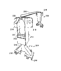
FIG. 3 is an orthographic view of a frame support for a wind turbine.
FIG. 4 is an orthographic view of a portion of the frame support shown in FIG.
3.
FIG. 5 is a side view of the stand assembly shown in FIGs. 3 and 4.
FIG. 6 is an exploded orthographic view of the stand assembly shown in FIG. 5.
DETAILED DESCRIPTION OF THE INVENTION
FIG. 3 illustrates one example of a frame support 200 for a wind turbine 4
having
frame 132 (FIG. 1) with a bedplate 203 that is connected to a rear frame 205.
- 2 -

CA 02669517 2009-06-18
230514
However, the frame support 200 may also be used with other frame
configurations,
such as a bedplate 203 and rear frame 205 that are formed a single, contiguous
unit or
more than two units. The frame support 200 may be provided in newly installed
construction and/or retrofitted into existing construction.
In these examples, the frame support 200 includes two stands 202, with one
stand 202
extending from each side of the bedplate 203 portion of the frame 132.
However, any
other number of stands 202 and/or stand positions may also be used. For
example, the
stands 202 may be provided on the rear frame 205 portion of the frame 132.
A tension member 204 extends from each of the forward and rear sides of each
of the
illustrated stands 202. One of the tension members 204 connects to the rear
frame
205 portion of the frame 132 while the other tension member connects to the
bedplate
203. However, any other number of tension members may be provided with either
or
both of the stands 202. For example, a single tension member may extend from
the
stand 202 to the rear frame 205. The tension members 204 may also be connected
directly between the bedplate 203 and rear frame 205 without a stands 202.
The illustrated tension members 204 are flexible chains. However, other
flexible and
inflexible tension members may also be used such as ropes, bars, beams,
straps, or
webs. Alternatively, or in addition, a stand (not shown) may extend from the
opposite
side of the frame 132 with compression members (nor shown) connecting the
downwardly extending stand to the rear frame 205 and/or or bedplate 203 on the
opposite side of the frame 132.
As best illustrated in FIG. 4, the illustrated stands 202 are also connected
to each other
by a brace member 206 arranged at the top of the stands. However, the brace
member
206 may be arranged at other positions on the stands 202 and/or the frame
support 200
may be provided without a brace member 206. Alternatively, tension members 202
may also be connected to the brace member 206 and/or any other number of
stands
202 and/or tension members 204 may be provided. For example, a single stand
202
may be provided with the tension members 204 connected to the stand and/or a
brace
member 206 extending from near the top of the single stand.
- 3 -

CA 02669517 2009-06-18
230514
As best illustrated in FIGs. 5 and 6, each of the illustrated stands 202
includes a base
208 which is supported by the bedplate 203, and a cap 210 for extending from
the base
208. In these examples, each of caps 210 also include ears 218 on each side
for
connecting to the corresponding tension members 204. However, the tension
members
204 may also be connected directly to caps 210 that are provided without the
ears.
Each of the illustrated bases 208 includes a substantially vertical column 212
and two
legs 214 for supporting the column 212 on the frame 132. However, the columns
212
may also be arranged in non-vertical orientations and/or any number of legs
214 may
also be provided. The columns 212 may also be secured and/or formed directly
on the
bedplate 203, or rear frame 205, with or without the legs 214. Each of the
illustrated
legs 214 is also be provided with feet 216 for stabilizing and securing the
base 208 to
the bedplate 203.
As best illustrated in FIG. 6, each of the illustrated caps 210 slides over
the top of the
columns 212. As best shown in FIGs. 4 and 5, a jack 220 is arranged between
the
bottom of the cap 210 and the top of the column 212 for moving the cap
relative to the
column 212 and tensioning the tension members 204. However, other tensioning
configurations may also be provided. For example, ratcheting chain load
binders may
be provided for tensioning the members 204.
The term "jack" is used here broadly to refer to any device or mechanism for
applying
a force between the cap 210 and the column 212. Although the bottle jack 220
is
illustrated here, screw, spring, hydraulic, pneumatic, mechanical, electrical,
and other
types of jacks may also be provided. In this configuration, the top of the
column 212
and the cap 210 are also provided with flanges 222 for positioning the jack
220 on the
stand 202.
It should be emphasized that the embodiments described above, and particularly
any
"preferred" embodiments, are merely examples of various implementations that
have
been set forth here to provide a clear understanding of various aspects of
this
technology. One of ordinary skill will be able to alter many of these
embodiments
without substantially departing from scope of protection defined solely by the
proper
construction of the following claims.
- 4 -

Representative Drawing
A single figure which represents the drawing illustrating the invention.
Administrative Status

2024-08-01:As part of the Next Generation Patents (NGP) transition, the Canadian Patents Database (CPD) now contains a more detailed Event History, which replicates the Event Log of our new back-office solution.

Please note that "Inactive:" events refers to events no longer in use in our new back-office solution.

For a clearer understanding of the status of the application/patent presented on this page, the site Disclaimer , as well as the definitions for Patent , Event History , Maintenance Fee  and Payment History  should be consulted.

Event History

Description Date
Letter Sent 2024-01-25
Inactive: Recording certificate (Transfer) 2024-01-25
Inactive: Multiple transfers 2023-12-29
Change of Address or Method of Correspondence Request Received 2023-01-16
Common Representative Appointed 2019-10-30
Inactive: IPC deactivated 2017-09-16
Grant by Issuance 2016-06-07
Inactive: Cover page published 2016-06-06
Inactive: First IPC assigned 2016-04-01
Inactive: IPC assigned 2016-04-01
Inactive: Final fee received 2016-03-23
Pre-grant 2016-03-23
Inactive: IPC expired 2016-01-01
Letter Sent 2015-12-10
Inactive: Single transfer 2015-12-02
Notice of Allowance is Issued 2015-10-22
Letter Sent 2015-10-22
Inactive: Approved for allowance (AFA) 2015-10-19
Inactive: QS passed 2015-10-19
Amendment Received - Voluntary Amendment 2015-09-30
Inactive: S.30(2) Rules - Examiner requisition 2015-05-04
Inactive: Report - QC passed 2015-05-01
Letter Sent 2014-04-22
Request for Examination Received 2014-04-10
Request for Examination Requirements Determined Compliant 2014-04-10
All Requirements for Examination Determined Compliant 2014-04-10
Change of Address or Method of Correspondence Request Received 2014-03-31
Application Published (Open to Public Inspection) 2009-12-19
Inactive: Cover page published 2009-12-18
Inactive: First IPC assigned 2009-10-13
Inactive: IPC assigned 2009-10-13
Inactive: Filing certificate - No RFE (English) 2009-07-13
Filing Requirements Determined Compliant 2009-07-13
Application Received - Regular National 2009-07-10

Abandonment History

There is no abandonment history.

Maintenance Fee

The last payment was received on 2016-06-01

Note : If the full payment has not been received on or before the date indicated, a further fee may be required which may be one of the following

  • the reinstatement fee;
  • the late payment fee; or
  • additional fee to reverse deemed expiry.

Please refer to the CIPO Patent Fees web page to see all current fee amounts.

Owners on Record

Note: Records showing the ownership history in alphabetical order.

Current Owners on Record
GENERAL ELECTRIC RENOVABLES ESPANA, S.L.
Past Owners on Record
JAMES D. ANTALEK
JOHN P. DAVIS
WIN NGUYEN
Past Owners that do not appear in the "Owners on Record" listing will appear in other documentation within the application.
Documents

To view selected files, please enter reCAPTCHA code :


To view images, click a link in the Document Description column. To download the documents, select one or more checkboxes in the first column and then click the "Download Selected in PDF format (Zip Archive)" or the "Download Selected as Single PDF" button.

List of published and non-published patent-specific documents on the CPD .

If you have any difficulty accessing content, you can call the Client Service Centre at 1-866-997-1936 or send them an e-mail at CIPO Client Service Centre.


Document
Description 
Date
(yyyy-mm-dd) 
Number of pages   Size of Image (KB) 
Abstract 2009-06-18 1 8
Description 2009-06-18 4 193
Claims 2009-06-18 2 52
Drawings 2009-06-18 4 111
Representative drawing 2009-11-23 1 12
Cover Page 2009-12-10 1 35
Description 2015-09-30 4 185
Claims 2015-09-30 2 51
Representative drawing 2016-04-18 1 10
Cover Page 2016-04-18 1 33
Maintenance fee payment 2024-05-21 50 2,057
Filing Certificate (English) 2009-07-13 1 157
Reminder of maintenance fee due 2011-02-21 1 112
Reminder - Request for Examination 2014-02-19 1 118
Acknowledgement of Request for Examination 2014-04-22 1 175
Commissioner's Notice - Application Found Allowable 2015-10-22 1 161
Courtesy - Certificate of registration (related document(s)) 2015-12-10 1 103
Correspondence 2014-03-31 1 23
Amendment / response to report 2015-09-30 6 187
Final fee 2016-03-23 1 34