Sélection de la langue

Search

Sommaire du brevet 2669517 

Énoncé de désistement de responsabilité concernant l'information provenant de tiers

Une partie des informations de ce site Web a été fournie par des sources externes. Le gouvernement du Canada n'assume aucune responsabilité concernant la précision, l'actualité ou la fiabilité des informations fournies par les sources externes. Les utilisateurs qui désirent employer cette information devraient consulter directement la source des informations. Le contenu fourni par les sources externes n'est pas assujetti aux exigences sur les langues officielles, la protection des renseignements personnels et l'accessibilité.

Disponibilité de l'Abrégé et des Revendications

L'apparition de différences dans le texte et l'image des Revendications et de l'Abrégé dépend du moment auquel le document est publié. Les textes des Revendications et de l'Abrégé sont affichés :

  • lorsque la demande peut être examinée par le public;
  • lorsque le brevet est émis (délivrance).
(12) Brevet: (11) CA 2669517
(54) Titre français: SUPPORT DE CADRE POUR EOLIENNE
(54) Titre anglais: FRAME SUPPORT FOR WIND TURBINE
Statut: Accordé et délivré
Données bibliographiques
(51) Classification internationale des brevets (CIB):
  • F03D 80/80 (2016.01)
  • F03D 13/20 (2016.01)
(72) Inventeurs :
  • DAVIS, JOHN P. (Etats-Unis d'Amérique)
  • ANTALEK, JAMES D. (Etats-Unis d'Amérique)
  • NGUYEN, WIN (Etats-Unis d'Amérique)
(73) Titulaires :
  • GENERAL ELECTRIC RENOVABLES ESPANA, S.L.
(71) Demandeurs :
  • GENERAL ELECTRIC RENOVABLES ESPANA, S.L. (Espagne)
(74) Agent: CRAIG WILSON AND COMPANY
(74) Co-agent:
(45) Délivré: 2016-06-07
(22) Date de dépôt: 2009-06-18
(41) Mise à la disponibilité du public: 2009-12-19
Requête d'examen: 2014-04-10
Licence disponible: S.O.
Cédé au domaine public: S.O.
(25) Langue des documents déposés: Anglais

Traité de coopération en matière de brevets (PCT): Non

(30) Données de priorité de la demande:
Numéro de la demande Pays / territoire Date
12/141,953 (Etats-Unis d'Amérique) 2008-06-19

Abrégés

Abrégé français

Support (200) pour une éolienne (2) comportant un cadre arrière (205) partant dun châssis (203). Le support comprend au moins un élément de tension (204) sallongeant entre le cadre arrière (205) et le châssis (203).


Abrégé anglais

A support (200) for a wind turbine (2) having rear frame (205) extending from a bedplate (203), where the support includes at least one tension member (204) extending between the rear frame (205) and the bedplate (203).

Revendications

Note : Les revendications sont présentées dans la langue officielle dans laquelle elles ont été soumises.


WHAT IS CLAIMED IS:
1. A wind turbine, comprising:
a tower;
a nacelle arranged on the tower;
a gearbox connected to an electrical generator arranged in the nacelle;
a blade rotating the gearbox and driving the generator;
a bedplate supporting the gearbox;
a rear frame, extending from the bedplate, supporting the generator;
at least one tension member extending between the rear frame and the
bedplate, and,
a stand extending therefrom the bedplate wherein the at least one tension
member connects the stand to the rear frame;
wherein the stand further comprises:
a base;
a cap, connected to the at least one tension member, extending from
the base; and
a jack extending the cap from the base.
2. The wind turbine recited in claim 1, wherein the jack is arranged
between the cap and the base.
3. The wind turbine recited in claim 1, wherein the jack is a bottle jack.
4. A wind turbine, comprising:
a tower;
a nacelle arranged on the tower;
a gearbox connected to an electrical generator arranged in the nacelle;
a blade rotating the gearbox and driving the generator;
a bedplate supporting the gearbox;
a rear frame, extending from the bedplate, supporting the generator;
a first stand extending from one side of the bedplate;
a first tension member extending between the first stand and the rear frame;
- 5 -

a second stand extending from an opposite side of the bedplate opposite
from the one side;
a second tension member extending between the second stand and the rear
frame;
a third tension member extending to the bedplate from an opposite side of
the first stand as the first tension member; and
a fourth tension member extending to the bedplate from an opposite side of
the second stand as the second tension member;
wherein each stand further comprises:
a base supported by the bedplate;
a cap, connected to the respective tension members, for extending
from the base; and
a jack extending the cap from the base.
5. The wind turbine recited in claim 4, wherein the jack is a bottle jack.
6. The wind turbine recited in claim 4, wherein each tension member
comprises a chain.
7. The wind turbine recited in claim 4, wherein each base further
comprises:
a substantially vertical column; and
at least one leg supporting the substantially vertical column on the bedplate.
8. The wind turbine recited in claim 7, wherein each column supports
the respective jack for extending the cap from the base.
9. The wind turbine recited in claim 8, wherein the jack is a bottle jack.
10. The wind turbine recited in claim 9, wherein each tension member
comprises a chain.
- 6 -

Description

Note : Les descriptions sont présentées dans la langue officielle dans laquelle elles ont été soumises.

CA 02669517 2015-09-30
230514
FRAME SUPPORT FOR WIND TURBINE
BACKGROUND OF THE INVENTION
1. Technical Field
The subject matter described here generally relates to wind turbines, and,
more
particularly, to a frame support for a wind turbine.
2. Related Art
A wind turbine is a machine for converting the kinetic energy in wind into
mechanical
energy. If the mechanical energy is used directly by the machinery, such as to
pump
water or to grind wheat, then the wind turbine may be referred to as a
windmill.
Similarly, if the mechanical energy is converted to electricity, then the
machine may
also be referred to as a wind generator or wind power plant.
Wind turbines are typically categorized according to the vertical or
horizontal axis
about which the blades rotate. One so-called horizontal-axis wind generator is
schematically illustrated in Figure 1 and available from General Electric
Company.
This particular configuration for a wind turbine 2 includes a tower 4
supporting a
nacelle 6 enclosing a drive train 8. The blades 10 are arranged on a hub to
form a
"rotor" at one end of the drive train 8 outside of the nacelle 6. The rotating
blades 10
drive a gearbox 12 connected to an electrical generator 14 at the other end of
the drive
train 8 arranged inside the nacelle 6 along with a control system 16 that
receives input
from an anemometer 18.
Conu-nonly-assigned U.S. Patent No. 7,126,236 for "Methods and Apparatus for
Pitch
Control Power Conversion" is partially reproduced in FIG. 2. In FIG. 2, the
drive
train 8 of the wind turbine 4 (shown in FIG. 1) includes a main rotor shaft
116
connected to hub 110 and the gear box 12. The control system 16 (FIG. 1)
includes
one or more microcontrollers within panel 112 which provide control signals to
variable pitch blade drive 114. A high speed shaft (not shown in FIG. 2) is
used to
drive a first generator 120 via coupling 122. Various
components
- 1 -

CA 02669517 2009-06-18
230514
are supported by a frame 132. The frame 132 typically includes a main frame or
"bedplate" portion, and generator support frame or "rear frame" portion that
is
cantilevered from the bedplate. However, the frame 132 may, under certain
conditions, be subject to high stresses that can cause fatigue cracking and/or
failure,
particularly at the joint between the bedplate and the generator support
frame.
BRIEF DESCRIPTION OF THE INVENTION
These and other drawbacks associated with such conventional approaches are
addressed here in by providing, in various embodiments, a support for a wind
turbine
having rear frame extending from a bedplate, where the support includes at
least one
tension member extending between the rear frame and the bedplate.
BRIEF DESCRIPTION OF THE DRAWINGS
Various aspects of this technology will now be described with reference to the
following figures ("FIGs.") which are not necessarily drawn to scale, but use
the same
reference numerals to designate corresponding parts throughout each of the
several
views.
FIG. 1 is a schematic side view of a conventional wind generator.
FIG. 2 is a cut-away orthographic view of the nacelle and hub of the
conventional
wind generator shown in FIG. 1.
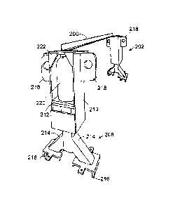
FIG. 3 is an orthographic view of a frame support for a wind turbine.
FIG. 4 is an orthographic view of a portion of the frame support shown in FIG.
3.
FIG. 5 is a side view of the stand assembly shown in FIGs. 3 and 4.
FIG. 6 is an exploded orthographic view of the stand assembly shown in FIG. 5.
DETAILED DESCRIPTION OF THE INVENTION
FIG. 3 illustrates one example of a frame support 200 for a wind turbine 4
having
frame 132 (FIG. 1) with a bedplate 203 that is connected to a rear frame 205.
- 2 -

CA 02669517 2009-06-18
230514
However, the frame support 200 may also be used with other frame
configurations,
such as a bedplate 203 and rear frame 205 that are formed a single, contiguous
unit or
more than two units. The frame support 200 may be provided in newly installed
construction and/or retrofitted into existing construction.
In these examples, the frame support 200 includes two stands 202, with one
stand 202
extending from each side of the bedplate 203 portion of the frame 132.
However, any
other number of stands 202 and/or stand positions may also be used. For
example, the
stands 202 may be provided on the rear frame 205 portion of the frame 132.
A tension member 204 extends from each of the forward and rear sides of each
of the
illustrated stands 202. One of the tension members 204 connects to the rear
frame
205 portion of the frame 132 while the other tension member connects to the
bedplate
203. However, any other number of tension members may be provided with either
or
both of the stands 202. For example, a single tension member may extend from
the
stand 202 to the rear frame 205. The tension members 204 may also be connected
directly between the bedplate 203 and rear frame 205 without a stands 202.
The illustrated tension members 204 are flexible chains. However, other
flexible and
inflexible tension members may also be used such as ropes, bars, beams,
straps, or
webs. Alternatively, or in addition, a stand (not shown) may extend from the
opposite
side of the frame 132 with compression members (nor shown) connecting the
downwardly extending stand to the rear frame 205 and/or or bedplate 203 on the
opposite side of the frame 132.
As best illustrated in FIG. 4, the illustrated stands 202 are also connected
to each other
by a brace member 206 arranged at the top of the stands. However, the brace
member
206 may be arranged at other positions on the stands 202 and/or the frame
support 200
may be provided without a brace member 206. Alternatively, tension members 202
may also be connected to the brace member 206 and/or any other number of
stands
202 and/or tension members 204 may be provided. For example, a single stand
202
may be provided with the tension members 204 connected to the stand and/or a
brace
member 206 extending from near the top of the single stand.
- 3 -

CA 02669517 2009-06-18
230514
As best illustrated in FIGs. 5 and 6, each of the illustrated stands 202
includes a base
208 which is supported by the bedplate 203, and a cap 210 for extending from
the base
208. In these examples, each of caps 210 also include ears 218 on each side
for
connecting to the corresponding tension members 204. However, the tension
members
204 may also be connected directly to caps 210 that are provided without the
ears.
Each of the illustrated bases 208 includes a substantially vertical column 212
and two
legs 214 for supporting the column 212 on the frame 132. However, the columns
212
may also be arranged in non-vertical orientations and/or any number of legs
214 may
also be provided. The columns 212 may also be secured and/or formed directly
on the
bedplate 203, or rear frame 205, with or without the legs 214. Each of the
illustrated
legs 214 is also be provided with feet 216 for stabilizing and securing the
base 208 to
the bedplate 203.
As best illustrated in FIG. 6, each of the illustrated caps 210 slides over
the top of the
columns 212. As best shown in FIGs. 4 and 5, a jack 220 is arranged between
the
bottom of the cap 210 and the top of the column 212 for moving the cap
relative to the
column 212 and tensioning the tension members 204. However, other tensioning
configurations may also be provided. For example, ratcheting chain load
binders may
be provided for tensioning the members 204.
The term "jack" is used here broadly to refer to any device or mechanism for
applying
a force between the cap 210 and the column 212. Although the bottle jack 220
is
illustrated here, screw, spring, hydraulic, pneumatic, mechanical, electrical,
and other
types of jacks may also be provided. In this configuration, the top of the
column 212
and the cap 210 are also provided with flanges 222 for positioning the jack
220 on the
stand 202.
It should be emphasized that the embodiments described above, and particularly
any
"preferred" embodiments, are merely examples of various implementations that
have
been set forth here to provide a clear understanding of various aspects of
this
technology. One of ordinary skill will be able to alter many of these
embodiments
without substantially departing from scope of protection defined solely by the
proper
construction of the following claims.
- 4 -

Dessin représentatif
Une figure unique qui représente un dessin illustrant l'invention.
États administratifs

2024-08-01 : Dans le cadre de la transition vers les Brevets de nouvelle génération (BNG), la base de données sur les brevets canadiens (BDBC) contient désormais un Historique d'événement plus détaillé, qui reproduit le Journal des événements de notre nouvelle solution interne.

Veuillez noter que les événements débutant par « Inactive : » se réfèrent à des événements qui ne sont plus utilisés dans notre nouvelle solution interne.

Pour une meilleure compréhension de l'état de la demande ou brevet qui figure sur cette page, la rubrique Mise en garde , et les descriptions de Brevet , Historique d'événement , Taxes périodiques et Historique des paiements devraient être consultées.

Historique d'événement

Description Date
Lettre envoyée 2024-01-25
Inactive : Certificat d'inscription (Transfert) 2024-01-25
Inactive : Transferts multiples 2023-12-29
Requête pour le changement d'adresse ou de mode de correspondance reçue 2023-01-16
Représentant commun nommé 2019-10-30
Inactive : CIB désactivée 2017-09-16
Accordé par délivrance 2016-06-07
Inactive : Page couverture publiée 2016-06-06
Inactive : CIB en 1re position 2016-04-01
Inactive : CIB attribuée 2016-04-01
Inactive : Taxe finale reçue 2016-03-23
Préoctroi 2016-03-23
Inactive : CIB expirée 2016-01-01
Lettre envoyée 2015-12-10
Inactive : Transfert individuel 2015-12-02
Un avis d'acceptation est envoyé 2015-10-22
Lettre envoyée 2015-10-22
Inactive : Approuvée aux fins d'acceptation (AFA) 2015-10-19
Inactive : QS réussi 2015-10-19
Modification reçue - modification volontaire 2015-09-30
Inactive : Dem. de l'examinateur par.30(2) Règles 2015-05-04
Inactive : Rapport - CQ réussi 2015-05-01
Lettre envoyée 2014-04-22
Requête d'examen reçue 2014-04-10
Exigences pour une requête d'examen - jugée conforme 2014-04-10
Toutes les exigences pour l'examen - jugée conforme 2014-04-10
Requête pour le changement d'adresse ou de mode de correspondance reçue 2014-03-31
Demande publiée (accessible au public) 2009-12-19
Inactive : Page couverture publiée 2009-12-18
Inactive : CIB en 1re position 2009-10-13
Inactive : CIB attribuée 2009-10-13
Inactive : Certificat de dépôt - Sans RE (Anglais) 2009-07-13
Exigences de dépôt - jugé conforme 2009-07-13
Demande reçue - nationale ordinaire 2009-07-10

Historique d'abandonnement

Il n'y a pas d'historique d'abandonnement

Taxes périodiques

Le dernier paiement a été reçu le 2016-06-01

Avis : Si le paiement en totalité n'a pas été reçu au plus tard à la date indiquée, une taxe supplémentaire peut être imposée, soit une des taxes suivantes :

  • taxe de rétablissement ;
  • taxe pour paiement en souffrance ; ou
  • taxe additionnelle pour le renversement d'une péremption réputée.

Veuillez vous référer à la page web des taxes sur les brevets de l'OPIC pour voir tous les montants actuels des taxes.

Titulaires au dossier

Les titulaires actuels et antérieures au dossier sont affichés en ordre alphabétique.

Titulaires actuels au dossier
GENERAL ELECTRIC RENOVABLES ESPANA, S.L.
Titulaires antérieures au dossier
JAMES D. ANTALEK
JOHN P. DAVIS
WIN NGUYEN
Les propriétaires antérieurs qui ne figurent pas dans la liste des « Propriétaires au dossier » apparaîtront dans d'autres documents au dossier.
Documents

Pour visionner les fichiers sélectionnés, entrer le code reCAPTCHA :


Pour visualiser une image, cliquer sur un lien dans la colonne description du document. Pour télécharger l'image (les images), cliquer l'une ou plusieurs cases à cocher dans la première colonne et ensuite cliquer sur le bouton "Télécharger sélection en format PDF (archive Zip)" ou le bouton "Télécharger sélection (en un fichier PDF fusionné)".

Liste des documents de brevet publiés et non publiés sur la BDBC .

Si vous avez des difficultés à accéder au contenu, veuillez communiquer avec le Centre de services à la clientèle au 1-866-997-1936, ou envoyer un courriel au Centre de service à la clientèle de l'OPIC.


Description du
Document 
Date
(aaaa-mm-jj) 
Nombre de pages   Taille de l'image (Ko) 
Abrégé 2009-06-18 1 8
Description 2009-06-18 4 193
Revendications 2009-06-18 2 52
Dessins 2009-06-18 4 111
Dessin représentatif 2009-11-23 1 12
Page couverture 2009-12-10 1 35
Description 2015-09-30 4 185
Revendications 2015-09-30 2 51
Dessin représentatif 2016-04-18 1 10
Page couverture 2016-04-18 1 33
Paiement de taxe périodique 2024-05-21 50 2 057
Certificat de dépôt (anglais) 2009-07-13 1 157
Rappel de taxe de maintien due 2011-02-21 1 112
Rappel - requête d'examen 2014-02-19 1 118
Accusé de réception de la requête d'examen 2014-04-22 1 175
Avis du commissaire - Demande jugée acceptable 2015-10-22 1 161
Courtoisie - Certificat d'enregistrement (document(s) connexe(s)) 2015-12-10 1 103
Correspondance 2014-03-31 1 23
Modification / réponse à un rapport 2015-09-30 6 187
Taxe finale 2016-03-23 1 34