Note: Descriptions are shown in the official language in which they were submitted.
CA 02669791 2009-05-15
WO 2008/061287 PCT/AU2007/001584
1
"A PADLOCK"
Field of the Invention
The present invention relates to a padlock and relates particularly, though
not
exclusively to a padlock suitable for improving the security of airline
luggage inspection.
Background to.the Invention
Due to the need to improve airport security the Transportation Security
Administration
(TSA) in the USA has requested that airline passengers not use padlocks on the
zippers of their luggage. The TSA conducts random intemal inspections on
airport
luggage. Approximately one in every six items of luggage are inspected. If a
conventional padlock has been used to secure the zipper or other closure, it
would
typically be "clipped" by the TSA should that item of luggage be subject to an
intemal
inspection. The padlock of a selected item of luggage is usually removed by
cutting
through the shackle of the lock with a pair of bolt cutters or similar tool.
Consequently,
a variety of specialised locks have been designed that can be re-attached to
the
luggage closure after they have been removed by a Luggage Inspector.
US Patent No 7,021,537 62 (Tropp) and US 7,037,728 B2 (Tropp) both relate to
this
type of system, in which a special lock is made available to airline
travellers, the special
lock typically having a combination lock portion and a master key lock
portion. A master
key, that can open the master key lock portion, is made available to airport
security
personnel to enable them to open the special lock in order to conduct an
internal
inspection of an item of luggage, and then securely reapply the lock to the
item of
luggage after the inspection. The special lock has an indicia provided on it
indicating to
airport security personnel that the lock can be opened using the master key.
The TSA
in the USA and other luggage screening authorities, now recognise such systems
and
the associated specialised padlocks. Most of the current specialised padlocks
involve
the use of a range of pass-keys that are held by the relevant agencies for
this purpose.
One of the problems with such prior art systems is that there is no way of
identifying
whether access to the item of luggage was conducted by authorised security
personnel. If a copy of the pass-key has fallen into the hands of an
unauthorised
person, they can open the special lock and remove valuables from, or plant an
object
in, the item of luggage undetected. Also, in order to work this system it is
required that
all security personnel be issued with the pass-keys for every variety of lock
that is
CA 02669791 2009-05-15
WO 2008/061287 PCT/AU2007/001584
2
currently on the market. This will become unmanageable as the number and
variety of
locks increases.
The present invention was developed with a view to providing a padlock that
does not
require the use of a special pass-key to be opened and can be reapplied to an
item of
luggage. It will be appreciated that the padlock of the present invention will
also have
many other applications and is not limited in its use to securing items of
luggage.
References to prior art documents in this specification are provided for
illustrative
purposes only and are not to be taken as an admission that such prior art is
part of the
common general knowledge in Australia or elsewhere.
Summary of the Invention
According to a first aspect of the present invention, there is provided a
padlock
comprising:
a lock body;
a plurality of shackles extending from the lock body, each shackle being
moveable
between a closed position and an open position; and
a locking mechanism engageable with each of the shackles such that operation
of the
locking mechanism with an access control means is required to move any shackle
in
the closed position to the open position;
wherein severing one of the shackles in the closed position results in one of
the other
shackles being in the open position and free to move to the closed position.
In one embodiment, when one of the shackles is in the closed position, the
other
shackles are prevented from being in the closed position and severing the
closed
shackle allows closing of one of the open shackles.
In a preferred embodiment, each of the shackles comprise part of an integral
shackle
member. The integral shackle member may comprises a double sided shackle, the
first
end of the double sided shackle comprising a first shackle and the second end
of the
double sided shackle comprising a second shackle such that moving the first
shackle to
the closed position results in the second shackle being moved to the open
position and
CA 02669791 2009-05-15
WO 2008/061287 PCT/AU2007/001584
3
moving the first shackle to the open position results in the second shackle
being moved
to the closed position.
Preferably, each of the shackles move slidably between the closed and open
positions
and each of the shackles interengage such that rotation of a portion of the
severed
shackle . causes the other shackle to move to the open position by said
interengagement.
In a preferred embodiment, the double sided shackle includes an intermediate
portion
between the first and second ends and the locking mechanism includes a tongue
member that engages with a first recessed portion in the intermediate portion
when the
first shackle is in the closed position and with a second recessed portion in
the
intermediate portion when the second shackle is in the closed position such
that
engagement of the tongue member with either the first or second recessed
portions
prevents sliding movement of the double sided shackle and wherein rotational
motion
of the double sided shackle is prevented by one of the shackles being in the
closed
position.
The intermediate portion may include a cam portion between the first and
second
recessed portions and wherein the first and second recessed portions are
arranged
such that rotational motion of the double sided shackle after severing the
closed
shackle moves the tongue member out of the recessed portion and allows the
double
sided shackle to slide to a position in which the tongue member is in the cam
portion,
the double sided shackle then being in a neutral position with neither the
first or second
shackles being closed.
Advantageously, the severed shackle is removable from the lock body for
replacement.
The intermediate portion may be received in a transverse groove in the lock
body and
wherein the double sided shackle can be removed from the transverse groove to
allow
replacement of the double sided shackle.
The locking control mechanism may comprise a lock barrel and the access
control
means comprises a key. In an alternative embodiment, the locking mechanism
comprises a combination type lock.
In a further embodiment, each of the shackles can simultaneously be in the
closed
position and severing of any shackle in the closed position causes other
shackles in the
closed position to move to the open position.
CA 02669791 2009-05-15
WO 2008/061287 PCT/AU2007/001584
4
Preferably, the padlock includes a first shackle and a second shackle
extending from
opposed sides of the lock body. The locking mechanism preferably includes a
key
barrel arranged in the lock body such that rotation of the key barrel with a
key causes
the first and second shackles to move to the open position. Alternatively, the
locking
mechanism may comprise a combination type lock and operation of the
combination
type lock causes the first and second shackles to move to the open position.
In one embodiment, each of the first and second shackles includes a first end
and a
second end, the first end being retained in the lock body by a retaining
spring in the
open position and the second end being engaged by a first latch plate in the
closed
position to hold the second end in the lock body in the closed position.
A second latch plate is preferably provided in engagement with the first latch
plate and
the key barrel such that rotation of the key barrel causes translation of the
second latch
plate and thereby of the first latch plate. The first latch plate may include
a first hole into
which is received the second end of the shackle, the second end having a first
notch
engaged by the edge of the hole to retain the second end of the shackle in the
closed
position.
The retaining spring preferably includes a pair of arms that engage with a
circular
groove in the first end of the shackle to retain the shackle and the second
latch plate
engages with the arms of the retaining spring in the closed position such that
severing
the shackle in the closed position allows release of the first end of the
shackle from the
lock body.
Ejector springs may be provided between the first end of the first shackle and
the
second end of the second shackle and between the second end of the first
shackle and
the first end of the second shackle such that the ejector springs eject the
first end of the
severed shackle from the lock body.
In a preferred embodiment, the first ends of the first and second shackles
include a
second notch which receives an end of the corresponding first latch plate and
wherein
during the ejection of the first end of the shackle, the first latch plate
rides out of the
second notch disengaging the first latch plate from the second end of the
severed
shackle, thereby allowing ejection of the second end of the severed shackle by
the
ejector spring. Preferably, the first and second notches are shaped such that
rotation of
either the first end or the second end of the severed shackle causes movement
of the
CA 02669791 2009-05-15
WO 2008/061287 PCT/AU2007/001584
first latch plate to disengage the first latch plate from both the first and
second notches,
thereby allowing ejection of the first and second ends of the severed shackle.
Advantageously, a latch interconnect member is provided, the latch
interconnect
member being engaged by the second latch plate of the severed shackle such
that the
5 latch interconnect causes movement of the second latch plate and the first
latch plate
of the unsevered shackle to allow the unsevered shackle to move to the open
position.
The latch interconnect may comprise an elliptical member having opposed arms
that
engage with the second latch plates of the first and second shackles, the
elliptical
member having an elliptical opening receiving a post member provided on the
inside of
the lock body.
The lower surface of the elliptical member may include lugs which slide in
slots
provided in the inner surface of the lock body such that the elliptical member
slides
from a central position in the direction of movement of the second latch plate
of the
severed shackle. Preferably the slots allow rotational motion of the
elliptical member
after the elliptical member has engaged with and moved the second latch plate
of the
unsevered member to allow clearance for re-closing of the unsevered latch
member.
According to another aspect of the present invention there is provided a
replaceable
shackle for a padlock, the shackle comprising:
a double-ended shackle adapted to be slidably received in a lock body of the
padlock
so as to have a first end extending from one side of the lock body and a
second end
extending from the opposite side of the lock body.
Preferably said double-ended shackle is C-shaped, having a first arcuate
portion at
said first end and a second arcuate portion at said second end. Typically said
first and
second arcuate portions are substantially identical in shape and
configuration.
Preferably the double-ended shackle further comprises a intermediate portion
joining
said first and second arcuate portions in facing relation. Preferably said
first and
second arcuate portions and said intermediate portion all lie in a single
plane.
According to a further aspect of the invention, there is provided a
replaceable shackle
for a padlock comprising a first end and a second end, the first end including
a circular
groove for receiving arms of a retaining spring in the padlock and the second
end
including a first notch for receiving a first latch plate in the padlock.
CA 02669791 2009-05-15
WO 2008/061287 PCT/AU2007/001584
6
The first end of the shackle may include a second notch for receiving an end
of the first
latch plate in the closed position. Preferably the shackle is generally U-
shaped.
Throughout the specification, unless the context requires otherwise, the word
"comprise" or variations such as "comprises" or "comprising", will be
understood to
imply the inclusion of a stated integer or group of integers but not the
exclusion of any
other integer or group of integers. Likewise the word "preferably" or
variations such as
"preferred", will be understood to imply that a stated integer or group of
integers is
desirable but not essential to the working of the invention.
Brief Description of the Drawings
The nature of the invention will be better understood from the following
detailed
description of several specific embodiments of the padlock, given by way of
example
only, with reference to the accompanying drawings, in which:
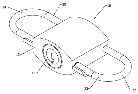
Figure 1 is a perspective view of a first embodiment of a padlock according to
the present invention;
Figure 2 is an exploded view of the padlock of Figure 1;
Figures 3 (a) and (b) illustrate a preferred embodiment of a double-ended
shackle employed in the padlock of Figure 1;
Figures 4 (a) and (b) illustrate the manner in which a lock tongue engages
with
the shackle employed in the padlock of Figure 1;
Figure 5 illustrates how the padlock of Figure 1 can be used to lock the
zipper
of an item of luggage;
Figure 6 illustrates how the shackle of the padlock of Figure 1 can be cut by
baggage inspection personnel;
Figure 7 illustrates how the padlock of Figure 1 can be removed from the
zipper
once the shackle is cut;
Figure 8 illustrates a first step in resetting the shackle employed in the
padlock
of Figure 1 by rotating the shackle 180 ;
CA 02669791 2009-05-15
WO 2008/061287 PCT/AU2007/001584
7
Figures 9 (a) and (b) illustrate what happens with the lock tongue when the
shackle employed in the padlock of Figure 1 is rotated 180 ;
Figure 10 illustrates a second step in resetting the shackle employed in the
padlock of Figure 1 by translating the shackle axially;
Figures 11 (a) and (b) illustrate what happens with the lock tongue in the
second step of resetting the shackle as shown in Figure 10;
Figure 12 illustrates a third step in resetting the shackle employed in the
padlock of Figure 1 by rotating the shackle back 180 ;
Figure 13 illustrates the padlock of Figure 1 reapplied to the zipper of an
item of
luggage in its reversed condition;
Figure 14 is a perspective view of a second embodiment of a padlock in
accordance with the present invention;
Figure 15 is an exploded view of the padlock of Figure 14;
Figure 16 shows cross sectional views of the padlock of Figure 14 with both
shackles in the open position;
Figure 17 shows cross sectional views of the padlock of Figure 14 with both
shackles in the closed position;
Figure 18 shows cross sectional views of the padlock of Figure 14 on severing
the first shackle;
Figure 19 shows cross sectional views of-the padlock of Figure 14 on ejection
of
the first shackle;
Figure 20 shows cross sectional views of the padlock of Figure 14 on
initiation
of release of the second shackle;
Figure 21 shows cross sectional views of the padlock of Figure 14 after
release
of the second shackle; and
Figure 22 shows cross sectional views of the padlock of Figure 14 after re-
closing the second shackle.
CA 02669791 2009-05-15
WO 2008/061287 PCT/AU2007/001584
8
Detailed Description of Preferred Embodiments
A first embodiment of a padlock 10 in accordance with the present invention is
illustrated in Figures 1 to 13. The padlock 10 comprises a lock body 12
housing a lock
mechanism 14. The lock mechanism 14 operates a plurality of shackles such that
operating the lock mechanism 14 with a suitable access control means (in this
case a
key) is required to move a shackle from a closed position to an open position.
In the
embodiment shown, two shackles are provided. The two shackles are provided as
an
integral shackle member in the form of a double-ended shackle 20.
The double-ended shackle 20 is slidably received in the lock body 12 so as to
have a
first end 22, comprising the first shackle 23, extending from one side of the
lock body
12 and a second end 24, comprising the second shackle 25, extending from the
opposite side of the lock body 12. Each end of the shackle 20 is moveable
between a
closed position in which it is engaged with the lock body 12 and an open
position in
which it is disengaged from the lock body 12. In the embodiment shown using
the
double ended shackle 20, the shackle 20 is lockable in one of two conditions:
a first
condition, in which the first shackle 23 is in the closed position, and a
second condition
in which the second shackle 25 is in the closed position. The padlock 10 is
arranged
such that severing of the shackle in the closed position allows the shackle in
the open
position to be moved to the closed position. The operation will be described
in more
detail below.
In this embodiment the lock mechanism 14 is of conventional barrel design.
However it
will be understood that any other suitable lock mechanism may be employed in
the
padlock 10 with any suitable access control means for locking the shackle in
the lock
body 12, such as, for example, a combination lock or an electronic lock
mechanism.
The lock mechanism 14 of this embodiment, as illustrated in Figure 2, is in
the form of
a lock barrel sub-assembly comprising a key barrel 30 which comes with the
required
key (not shown) and is supplied to the user with the padlock 10. Four lock
pins 32, a
lock tongue 34, and a lock tongue spring 36 are provided in connection with
the key
barrel 30. The key barrel 30 is housed in an outer barrel 38, and is retained
by two key
barrel cam followers 40 received in respective cam grooves in the outer barrel
38, and
a retaining ring 42 received in a recess 44 in the outer barrel 38. A lock pin
retaining
spring 46 clips over the outside of the outer barrel 38, and retains the four
lock pins 32
in the key barrel 30 under a slight load. This forms the completed lock barrel
sub-
CA 02669791 2009-05-15
WO 2008/061287 PCT/AU2007/001584
9
assembly, which is housed in a lock body cylinder 48 provided in the lock body
12. The
lock barrel sub-assembly is prevented from moving rearwards by the expanded
retaining ring 42 which locks over a retaining ring shoulder 50 provided
within the lock
body cylinder 48.
Preferably the double-ended shackle 20 is C-shaped. Typically the first and
second
arcuate portions 22 and 24 are substantially identical in shape and
configuration.
However this is by no means essential to the invention. One end of the shackle
20
could be considerably longer than the other, and/or the two ends could be of
different
shapes. The ends of the double-ended shackle 20 need not be arcuate but could
be of
any desired shape and configuration, for example of rectangular shape.
The C-shackle 20 includes an intermediate portion 52 joining the first and
second ends
22 and 24, as can be seen in Figures 3 and 4. In this embodiment the first and
second
ends 22 and 24 and the intermediate portion 52 all lie in a single plane;
however this
also is not essential and depends on how the shackle 20 is designed to mate
with the
lock body 12.
The lock body 12 has a transverse groove 26 formed in the back end thereof for
receiving the intermediate portion 52 of the C-shackle 20 when the lock 10 is
in an
assembled condition. First and second apertures 28a and 28b are provided in
respective side faces of the lock body 12 for receiving the mating ends of the
end
portions 22 and 24 respectively of the C-shackle 20 when the lock is in either
one of
the first and second conditions. A respective shackle seating spring 29 is
provided in
each aperture 28. A half-sleeve 31 is provided adjacent each aperture 28 and
is
designed to support the mating ends of the C-shackle 20 when it is in its
neutral
position.
The intermediate portion 52 of the C-shackle 20 is received in a shackle
channel 54
provided transversely in the outer barrel 38 of the lock barrel sub-assembly.
The lock
barrel sub-assembly is prevented from moving forwards by the C-shackle 20 as
it
mates with the shackle channel. The C-shackle 20 is a sacrificial shackle
which can be
removed from and replaced in the lock body with a replacement C-shackle, if
either one
of the first and second ends of the shackle 20 is damaged. Under certain
conditions,
the rear of the lock barrel sub-assembly can be partially exposed by ejecting
it from the
lock body 12 (see below). This exposes the shackle channel 54 so that a
replacement
C-Shackle 20 can be installed. The barrel sub-assembly can then be re-engaged
with
CA 02669791 2009-05-15
WO 2008/061287 PCT/AU2007/001584
the lock body 12 to entrap the C-Shackle in the shackle channel 54 and the
groove 26
of the lock body 12. Only one side of the C-Shackle is required to perform the
locking
function. Should one side of the C-Shackle be clipped by a Luggage Inspector
for the
purposes of removing the padlock 10, the opposite end of the C-shackle can be
used
5 to re-lock the device after the luggage inspection has been completed. As
will be
described in more detail below, no key is required to complete this process.
As can be seen most clearly in Figures 3 and 4, the lock tongue 34 has a
rounded tip
56 with two substantially parallel, flat side faces. The intermediate portion
52 of the C-
shackle 20 is provided with a portion 58 adapted to engage with the side faces
of the
10 tip 56 of lock tongue 34. The portion includes two recessed portions 58a
and 58b. The
first recessed portion 58a engages with the tip 56 of the lock tongue when the
shackle
is in the first condition, and the second recessed portion 58b engages with
the tip 56 of
the lock tongue when the shackle is in the second condition. Figure 4
illustrates the tip
56 of the lock tongue engaged in the first recessed portion 58a.
Preferably the intermediate portion 52 of the C-shackle further comprises a
cam portion
60 located intermediate the first and second recessed portions 58a and 58b, at
a
shackle mid-point. The cam portion 60 is designed to enable the lock tongue 34
to be
held in a neutral position when it is disengaged from either one of the first
and second
recessed portions 58a and 58b. The tip 56 of the lock tongue 34 can be
disengaged
from either one of the first and second recessed portions 58a and 58b by
rotating the
C-shackle in the shackle channel 54. The amount of rotation required for
disengagement will depend on the shape of the lock tongue 34 and the recessed
portion 58a or 58b. In the embodiment shown, disengagement would occur on
rotation
by around 35 degrees. The cam portion 60 can then be engaged with the tip 56
of the
lock tongue by sliding the intermediate portion 52 of the C-shackle in an
axial direction
in the shackle channel 54. When the C-shackle is rotated back , the tip 56 of
the lock
tongue acts like a cam follower and is lifted by the cam portion 60 to
approximately the
outer diameter of the intermediate portion 52 of the C-shackle 20. The cam
portion 60
has a concave profile designed to retain the rounded tip 56 of the lock tongue
34
therein in a neutral position.
A typical procedure for using the padlock 10 for locking a zipper 70 of an
item of
luggage (not shown) subject to internal inspection will now be described with
reference
to Figures 5 to 13.
CA 02669791 2009-05-15
WO 2008/061287 PCT/AU2007/001584
11
The padlock 10 is first presented with the C-Shackle 20 in its neutral
position (i.e.
neither of the two mating ends 22 and 24 are engaged in apertures 28a and 28b
of the
lock body 12). The lock 10 is then attached to the zipper 70 of a suitcase in
a similar
manner to a normal padlock, by closing one end (in the example shown, the
first end
22) of the C-Shackle 20 as shown in Figure 5. If needs be the shackle 20 can
be
released by the owner of the suitcase when the key is inserted into the key
barrel 30
and the lock 10 is unlocked by rotating the key to its release position. This
has the
effect of withdrawing the tip 56 of the lock tongue 34 from the first recessed
portion
58a, so that the intermediate portion 52 of the shackle 20 is free to slide in
the shackle
channel 54. The shackle seat spring 29 aids in this process by pushing the C-
Shackle
to its neutral position.
In the situation where a Luggage Inspector wishes to inspect the interior of
the
suitcase, he or she clips the first end 22 of the shackle 20 to remove the
lock 10 as
shown in Figures 6 and 7. The lock 10 can then be reinstated after inspection
by
15 returning the shackle 20 to its neutral position despite the absence of a
key. This is
accomplished by firstly rotating the C-shackle 180 as shown in Figure 8, and
then
pushing the unclipped second end 24 of the C-shackle towards the lock body
(one
click) as shown in Figure 10. When the C-shackle 20 is first rotated 180 the
rounded
tip 56 of the lock tongue 34 will slide out of the first recessed portion 58a
as shown in
20 Figure 9. When the unclipped second end 24 of the C-shackle is pushed so as
to slide
the intermediate portion 52 axially in the shackle channel 54 of the lock body
12, the tip
56 of the lock tongue 34 will eventually engage in the convex surface of the
cam
portion 60 at the shackle mid-point, as shown in Figure 11. The user will feel
and/or
hear a first "click" as the tip 56 of the lock tongue 34 seats in the cam
portion 60. The
C-shackle 20 is now in its neutral position.
The C-Shackle 20 is then rotated 180 back to its operating position, as shown
in
Figure 12, and the lock 10 can then be used once more, albeit by utilising the
opposite
end 24 of the shackle. The second end 24 of the shackle 20 can be applied to
the
zipper 70 as shown in Figure 13. The lock 10 is relocked by pushing the mating
end of
the shackle into the second aperture 28b. This will have the effect of forcing
the second
recessed portion 58b, on the intermediate portion 52 of the shackle, to engage
the tip
56 of the lock tongue 34. The user will feel and/or hear a second "click" as
the tip 56
seats in the second recessed portion 58b.
CA 02669791 2009-05-15
WO 2008/061287 PCT/AU2007/001584
12
A used (clipped) C-shackle 20 can be replaced with a new (spare) C-shackle.
This is
done by inserting the key into the front face of the barrel sub-assembly and
rotating it
90 in a clockwise direction. This rotates the key barrel 30 in relation to
the outer barrel
38, and aligns the deeper ends of the two cam grooves of the key barrel with
the two
key barrel cam followers 40. This gives the key barrel cam followers 40 the
required
space to be displaced radially inwards when the retaining ring 42 is
compressed. The
retaining ring 42 is compressed by the retaining ring shoulder 50 when the
front face'of
the barrel sub-assembly is pushed inwards (rearwards) relative to the lock
body 12.
This allows the barrel sub-assembly to slide along the lock body cylinder 48
rearwards,
and causes the opposite end of the barrel sub-assembly to emerge from the lock
body
12. The shackle channel 54 will thus be exposed allowing the damaged C-shackle
to
be replaced. The movement of the barrel sub-assembly in relation to the lock
body 12
is restricted by the boss of the lock key (not shown), which is wider than the
diameter of
the lock body cylinder 48. The installation of the new C-shackle 20 is
completed when
the shackle has been aligned with the transverse groove 26 in the lock body
12, and
when the barrel sub-assembly has been pushed back into the lock body 12. The
retaining ring 42 once again expands to the locked position as it passes the
retaining
ring shoulder 50 in the lock body cylinder 48. At this stage, the key can be
removed.
Figures 14 to 22 show a second embodiment of a padlock 10 in accordance with
the
present invention. Again in this embodiment, the padlock comprises a lock body
12
housing a locking mechanism 14. Also, two shackles are provided. In this
example
however, the first and second shackles 23 and 25 are provided as separate
elements.
Further, the first and second shackles may both independently be in either a
closed or
open position. In the embodiment shown in Figures 1 to 13, one of the shackles
remained in the open position and severing of the other shackle allowed the
open
shackle to be moved to the closed position. In the embodiment of Figures 14 to
22,
both of the first and second shackles 23 and 25 may simultaneously be in the
closed
position. In this state, severing one of the shackles results in the other
shackle moving
to the open position, from which it is free to move back to the closed
position. The
operation will be described in more detail below.
The first and second shackles 23 and 25 each comprise a generally U-shaped
member
having a first end 82 and a second end 84. The lock body 12 is provided with
first and
second longitudinal openings 86 and 88 such that the ends of the first shackle
23 are
received in the longitudinal openings 86 and 88 on a first side of the body 12
and the
CA 02669791 2009-05-15
WO 2008/061287 PCT/AU2007/001584
13
ends of the second shackle 25 are received in the first and second
longitudinal
openings 86 and 88 on a second side of the lock body 12. The first end 82 of
the first
shackle 23 is therefore co-linear with the second end 84 of the second shackle
25 and
the second end 84 of the first shackle 23 is co-linear with the first end 82
of the second
shackle 25.
The locking mechanism 14 comprises a key barrel 30 mounted in the lock body
12.
The key barrel 30 can be rotated by a corresponding key (not shown) such that
rotation
of the key releases the second ends 84 of the first and second shackles 23 and
25
from the lock body 12.
Each shackle 23 and 25 is provided with a first latch plate 90, a second latch
plate 92
and a latch spring 98. Each of the latch plates 90 and 92 are mounted
generally
transverse to ends of the corresponding shackle 23 and 25. The first latch
plate 90
includes a first hole 96 that receives the second end 84 of the corresponding
shackle
23 or 25. The first latch plate 90 is spring biased by a latch spring 98 to
move towards
the first end 82 of the shackle. The second end 84 of the shackle includes a
first notch
100 such that the first notch 100 engages with the first hole 96 to retain the
second end
84 of the shackle.
The second latch plate 92 includes a lug 102 that is received in a second hole
104 in
the first latch plate 90 such that movement of the second latch plate 92
causes
movement of the first latch plate 90. The second latch plate 92 is engaged by
protrusions 106 on the key barrel 30 such that rotation of the key barrel 30
causes
sliding motion of the second latch plate 92 towards the second end 84 of the
shackle
23 or 25.
The first ends 82 of the shackles 23 and 25 are each retained in the lock body
12 by a
corresponding retaining spring 108. The retaining spring 108 includes a pair
of spring
biased arms which engage with a circular groove 110 adjacent the first end 82
to
prevent the first end 82 being removed from the lock body 12. Further, the
longitudinal
openings 86 and 88 are provided with ejector springs 112 extending between
ends of
the shackles 23 and 25 to bias the shackles 23 and 25 to move outwardly
relative to
the lock body 12. The ejector springs 112 are provided with latch cam members
113
received in the ends of the ejector springs adjacent the second ends of the
shackles 23
and 25. The latch cam members 113 slide in channels provided in the
longitudinal
openings 86 and 88.
CA 02669791 2009-05-15
WO 2008/061287 PCT/AU2007/001584
14
The normal, key operated opening and closing of the shackles 23 and 25 can be
seen
with reference to Figures 16 and 17. Rotation of the key barrel 30 causes
movement of
the second latch plates 92 towards the second ends 84 of the shackles 23 and
25 by
engagement with the protrusions 106. The second latch plate 92 moves the first
latch
plate 90 such that the edge of the first hole 96 disengages from the first
notch 100. The
ejector springs 112 push the shackles 23 and 25 away from the lock body 12
until the
retaining springs 108 engages with the circular grooves 110. Both shackles 23
and 25
are then in the open position and can be closed by the reverse action.
When it is required for a closed shackle 23 or 25 to be opened via severing
the
shackle, the operation is as shown in Figure 18 and 19. The second latch plate
92
includes an end 114 adjacent the first end 82 of the shackle 23 or 25 that
engages with
the retaining spring 108 when the shackle 23 or 25 is in the closed position.
The end
114 of the second latch plate 92 spreads the arms of the retaining spring 108
in the
closed position. As can be seen in Figures 18 and 19, if the first shackle 23
is severed,
the first end 82 is therefore free to be ejected from the lock body 12 by the
ejector
spring 112.
The first end 82 of the shackle 23 also includes a second notch 116 in which
the
adjacent end of the first latch plate 90 rests in the closed position. The
second notch
116 is tapered such that as the first end 82 is being ejected, the first latch
plate 90 rides
up and out of the second notch 116. This action moves the first latch plate 90
towards
the second end 84 of the shackle 23 thereby disengaging the first hole 96 from
the first
notch 100 and allowing the second end 84 of the shackle to also be ejected
from the
lock body 12 (as shown in Fig 19).
On ejection of the first end 82 and the second end 84 of the shackle 23, the
second
latch plate 92 move further towards the first longitudinal opening 86 under
the action of
the latch spring 98.. The padlock 10 is also provided with a latch
interconnect member
118 such that this movement of the second latch plate 92 causes movement of
the
second latch plate 92 of the second shackle 25 (as seen in Figure 20). The
movement
of the second latch plate 92 of the first shackle 23 caused by the latch
spring 98 is
limited by the balancing action of the latch spring 98 of the second shackle
25 (through
the latch interconnect member 118). However, on ejection of the second end 84
of the
first shackle 23, the latch cam member 113 acts against an angled end surface
94 of
the second latch plate 92 (as can be seen in Figure 19) to move the second
latch plate
92 and thereby the first latch plate 90 towards the first longitudinal opening
86. The first
CA 02669791 2009-05-15
WO 2008/061287 PCT/AU2007/001584
latch plate 90 therefore moves across to seal the longitudinal openings 86 and
88 as
can be seen in Figure 21.
The arrangement of the first and second notches 100 and 116 in the shackle 23
is also
such that rotation of either end 82 or 84 of the severed shackle will result
in ejection of
5 both the first and second ends 82 and 84 of the severed shackle 23. As each
of the first
and second notches 100 and 116 are provided in one side only of the end 82 and
84,
rotation of either end 82 and 84 disengages that notch from the first latch
plate 90 and
causes movement of the first latch plate 90 such that the other notch is also
disengaged. Therefore, in the event that the ends 82 and 84 of the shackle 23
are not
10 ejected as described previously, rotation of either end 82 and 84 will
cause this to
happen. As it is expected that someone severing the shackle 23 will need to
cause
such rotation to remove the padlock 10, this ensure that the device operates
correctly
in unforseen circumstances.
The latch interconnect member 118 comprises an elliptical member 120 having an
15 elliptical central opening 122. A post member 124 is provided on the inside
of the lock
body 12. The post member 124 is received in the elliptical opening 122. Also
provided
is an interconnect spring 126 extending across the elliptical opening 122 and
through a
slot in the post member 124. The elliptical member 120 includes opposed arms
128
engaged by the second latch plates 92 such that motion of the second latch
plate 92 of
the first shackle 23 when cut causes motion of the second latch plate 92 of
the second
shackle 25.
The lower surface of the elliptical member 120 also includes lugs 130 which
slide inside
slots 132 in the inner surface of the lock body 12. The slots 132 allow the
elliptical
member 120 to slide initially parallel to the motion of the second latch
plates 92. As
shown in Figure 21, the elliptical member 120 having moved to engage and move
the
second latch plate 92 of the second shackle 25 then partially rotates by
movement of
the lugs 130 in the slots 132 deforming the interconnect spring 126. This
rotational
motion allows clearance for the first latch plate 90 of the second shackle 25
to re-
engage with the second shackle 25 to allow the second shackle to be closed (as
shown
in Figure 21) without the first shackle 23.
As in the first described embodiment, the severed shackle 23 can be later
replaced,
restoring the padlock 10 to its original condition for re-use.
CA 02669791 2009-05-15
WO 2008/061287 PCT/AU2007/001584
16
Now that preferred embodiments of the padlock have been described in detail,
it will be
apparent that it provides a number of advantages over the prior art, including
the
following:
(i) Once clipped by a Luggage Inspector of the TSA or other luggage screening
authority, the lock can be easily refitted post-inspection without the need
for
a pass-key.
(ii) Unauthorised access post inspection can only be achieved by cutting the
second lock portion.
(iii) A self-evident indication of the inspection and/or the interference is
thus
automatically provided to the owner.
(iv) Spare shackles can be marketed as a consumable component.
(v) The lock has been designed to work in conjunction with a zip
immobilisation
system.
It will be readily apparent to persons skilled in the relevant arts that
various
modifications and improvements may be made to the foregoing embodiments, in
addition to those already described, without departing from the basic
inventive
concepts of the present invention. For example, it is not essential that the
shackle be
replaceable; the lock could be designed as a single use item so that once it
has been
clipped by a Luggage Inspector a new lock would need to be purchased.
Therefore, it
.20 will be appreciated that the scope of the invention is not limited to the
specific
embodiments described.