Language selection

Search

Patent 2669852 Summary

Third-party information liability

Some of the information on this Web page has been provided by external sources. The Government of Canada is not responsible for the accuracy, reliability or currency of the information supplied by external sources. Users wishing to rely upon this information should consult directly with the source of the information. Content provided by external sources is not subject to official languages, privacy and accessibility requirements.

Claims and Abstract availability

Any discrepancies in the text and image of the Claims and Abstract are due to differing posting times. Text of the Claims and Abstract are posted:

  • At the time the application is open to public inspection;
  • At the time of issue of the patent (grant).
(12) Patent Application: (11) CA 2669852
(54) English Title: SAFETY DEVICE FOR QUICKLY RELEASING CONTROL ROPES OF ROMAN SHADES
(54) French Title: DISPOSITIF DE SECURITE PERMETTANT DE DEBLOQUER RAPIDEMENT LES CORDONNETS DE VOILAGES A L'ITALIENNE
Status: Dead
Bibliographic Data
(51) International Patent Classification (IPC):
  • E06B 9/324 (2006.01)
  • E06B 9/32 (2006.01)
(72) Inventors :
  • LIANG, WEN YING (Taiwan, Province of China)
  • HSU, SHENG YING (Taiwan, Province of China)
(73) Owners :
  • HSU, BEN (Canada)
(71) Applicants :
  • HSU, BEN (Canada)
(74) Agent: NA
(74) Associate agent: NA
(45) Issued:
(22) Filed Date: 2009-06-17
(41) Open to Public Inspection: 2010-09-06
Availability of licence: N/A
(25) Language of filing: English

Patent Cooperation Treaty (PCT): No

(30) Application Priority Data:
Application No. Country/Territory Date
098203393 Taiwan, Province of China 2009-03-06

Abstracts

English Abstract


A safety device for Roman shades includes multiple loop members connected
to the shade and multiple restriction members are connected to multiple loop
members.
Each restriction member includes two extensions which spirally wrap to each
other so
as to define an opening therebetween. Multiple engaging members are connected
to the
lowest loop members and each engaging member has two claws between which a
through hole is defined. Each claw includes a slit defined axially in a distal
end thereof.
Multiple control ropes each have a top end connected to the top box and the
lower end
of each control rope extends through the openings of the restriction members
and is
connected to an insertion member which is inserted into the silts and engaged
with the
through hole of the engaging member corresponding thereto. When the control
ropes
are pulled laterally, the insertion members are disengaged from the engaging
members.
Fig. 3


Claims

Note: Claims are shown in the official language in which they were submitted.


THE EMBODIMENTS OF THE INVENTION IN WHICH AN EXCLUSIVE
PROPERTY OR PRIVILEGE IS CLAIMED ARE DEFINED AS FOLLOWS:
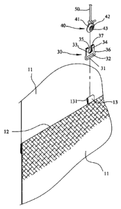
1. A Roman shade comprising:

a top box;

a shade composed of a fabric sheet and a top end of the shade connected to the

top box and multiple pocket portions formed along a first side of the shade,
the pocket
portions each being defined by folding upward a part of the fabric sheet and
fixing the
part along a folding line, each pocket portion defining a passage which
extends
transversely through the shade, rods extending through the passages, multiple
loop
members connected to each of the folding lines;

the loop members located at the lower end of the shade each connected with
an engaging member and each engaging member including two claws extending
therefrom in the same direction, a through hole defined between the two claws
and an
opening located between the two claws and communicating with the through hole,
each
claw including a slit defined axially in a distal end thereof;

two control ropes each having a first end connected to the top box and a
second end of each of the two control ropes extending through the loop
members;

two insertion members connected to the two respective second ends of the two
control ropes, the insertion members inserted into the slits of the two claws
via the
openings and engaged with the through holes, the claws clamping the insertion
members to position the insertion members between the two claws, when the
control

11


ropes are pulled beyond a clamping force applied to the insertion members, the

insertion members are disengaged from the slits and the through holes of the
two claws.

2. The Roman shade as claimed in claim 1, wherein each of the engaging
members includes a connection portion which has an elongate slot, the elongate
slot of
the connection portion of each of the engaging members is connected to one of
the loop
members.

3. The Roman shade as claimed in claim 1, wherein each of the two claws of
each of the engaging members includes a stop extending inward from an inside
thereof,
the opening is defined between the two stops and the through hole is defined
between
the insides of the two claws and the stops, the slit is defined in the distal
end of each
claw and the stop of each of the claws.

4. The Roman shade as claimed in claim 1, wherein the engaging members are
made of plastic material.

5. The Roman shade as claimed in claim 1, wherein the engaging members are
made of metallic material.

6. The Roman shade as claimed in claim 1, wherein each of the insertion
members is a ring-shaped member and includes a ramp portion on two sides
thereof and
a passage is defined through each of the insertion members, an annular lip
extends from
a periphery of the passage and is engaged with a periphery of the through hole
of the
engaging member.


12


7. The Roman shade as claimed in claim 1, wherein each of the insertion
members is made of plastic material.


8. The Roman shade as claimed in claim 1, wherein multiple restriction
members are connected to the loop members except for the loop members
connected
with the engaging members, each restriction member including a ring, a bent
first
extension and a bent second extension are connected to the ring, a gap is
defined
between the first and second extensions, a restriction hole is defined between
the first
and second extensions and communicates with the gap, the control rope extends
through the restriction hole.


9. The Roman shade as claimed in claim 8, wherein the bent first extension
and the bent second extension have a conjunction end which is fixed to the
ring and
extend across each other to define the restriction hole.


10. A Roman shade comprising:
a top box;

a shade having a top end thereof connected to the top box and multiple
restriction members connected to the top box, each restriction member
connected to an
engaging member which has two claws extending therefrom in the same direction,
a
through hole defined between the two claws and an opening located between the
two
claws and communicating with the through hole, each claw includes a slit
defined
axially in a distal end thereof, and


13


two control ropes each having a first end connected to the shade and a second
end of each of the two control ropes connected to an insertion member which is
inserted
into the opening and engaged with the through hole of the engaging member
corresponding to the control rope, when the control ropes are pulled beyond a
clamping
force applied to the insertion members, the insertion members are disengaged
from the
slits and the through holes of the two claws.


11. The Roman shade as claimed in claim 10, wherein each of the two claws
of each of the engaging members includes a stop extending inward from an
inside
thereof, the opening is defined between the two stops and the through hole is
defined
between the insides of the two claws and the stops, the slit is defined in the
distal end of
each claw and the stop of each of the claws.


12. The Roman shade as claimed in claim 10, wherein each of the insertion
members is a ring-shaped member and includes a ramp portion on two sides
thereof and
a passage is defined through each of the insertion members, an annular lip
extends from
a periphery of the passage and is engaged with a periphery of the through hole
of the
engaging member.


14

Description

Note: Descriptions are shown in the official language in which they were submitted.


CA 02669852 2009-06-17

SAFETY DEVICE FOR QUICKLY RELEASING CONTROL ROPES OF
ROMAN SHADES

FIELD OF THE INVENTION

The present invention relates to a Roman shade, and more particularly, to a
safety device for quickly releasing the control ropes of Roman shade when the
control
ropes are pulled abnormally.

BACKGROUND OF THE INVENTION

A conventional Roman shade includes a shade which generally is a fabric
sheet and the fabric sheet has one end fixed to the top box and a lot of
folded portions
are formed on the inside and/or outside of the shade so as to establish
specific

decoration features. A lot of passages are defined transversely through the
shade and
rods extend through the passage to define sections of the shade. Multiple
rings are
fixedly connected to the folding lines of the shade. Two control ropes each
have a first
end connected to a control mechanism in the top box and the other end of each
control

rope extends through the rings and is fixed to the lowest rings. The user can
lift and
lower the shade by pull of the control ropes.

When pulling the control ropes, the lowest rings are lifted and the sections
of
the shade are collected upward one by one by the pulling force applied to the
rings.
However, the control ropes are exposed and children may play the control ropes
and

this can be dangerous when the control ropes tangle the kids. The control
ropes tangle
the kids tightly when the kids struggle.

2


CA 02669852 2009-06-17

The present invention intends to provide a safety device for Roman shades
and which includes multiple engaging members connected to the lower end of the
shade.
When the control ropes are pulled laterally, the control ropes are easily
disengaged from
the engaging members and do not tangle the children.

SUMMARY OF THE INVENTION

The present invention relates to Roman shade which comprises a top box and
the top end of the fabric sheet of the shade is connected to the top box and
multiple
pocket portions are formed along a first side of the shade. The pocket
portions each are
defined by folding upward a part of the fabric sheet and then fixed the part
along a

folding line. Multiple loop members are connected to each of the folding
lines. Multiple
restriction members are connected to the multiple loop members. The loop
members
located at the lower end of the sheet each are connected with an engaging
member and
each engaging member includes two claws extending therefrom in the same
direction. A
through hole is defined between the two claws and an opening is located
between the

two claws and communicates with the through hole. Each claw includes a slit
defined
axially in a distal end thereof. Two control ropes each have a first end
connected to the
top box and a second end of each of the two control ropes extends through the
loop
members. Two insertion members are connected to the two respective second ends
of
the two control ropes and inserted into the slits of the two claws via the
openings and

engaged with the through holes. The claws clamp the insertion members to
position the
insertion members between the two claws. When the control ropes are pulled
beyond a
3


CA 02669852 2009-06-17

clamping force applied to the insertion members, the insertion members are
disengaged
from the slits and the through holes of the two claws.

The primary object of the present invention is to provide a safety device for
Roman shades wherein the control ropes can be easily loosen from the shade
when they
are pulled laterally so as to prevent children from playing and being tangled.

Another object of the present invention is to provide a safety device for
Roman shades wherein the restriction members of the safety device can be made
of
metal or plastic material. The restriction members can be manufactured easily
at low
cost.

Yet another object of the present invention is to provide a safety device for
Roman shades wherein the restriction members of the safety device includes two
extensions and a gap is defined between the two extensions, so that the
control rope can
be escaped from the gap.

A further object of the present invention is to provide a safety device for
Roman shades wherein the engagement of the insertion members and the engaging
members can be used to the scroll-type shade and the control ropes can be
escaped
when the control ropes are pulled abnormally.

The present invention will become more obvious from the following
description when taken in connection with the accompanying drawings which
show, for
purposes of illustration only, a preferred embodiment in accordance with the
present
invention.

4


CA 02669852 2009-06-17

BRIEF DESCRIPTION OF THE DRAWINGS

Fig. 1 is a perspective view of the Roman shade with the safety device of the
present invention;

Fig. 2 is an enlarged view to show that the control rope extends through the
restriction hole of the restriction member of the safety device of the present
invention;
Fig. 3 is an exploded view to show the engaging member and the insertion

member connected to the control rope of the safety device of the present
invention;

Fig. 4 is an enlarged view to show that the insertion member on the control
rope is engaged with the engaging member of the safety device of the present
invention;
Fig. 5 shows that the lower portion of the Roman shade is pulled upward;

Fig. 6 is an enlarged view to show that two restriction members are collected
together when the lower portion of the Roman shade is pulled upward, and the
insertion
member is still engaged with the engaging member;

Fig. 7 shows that the lower portion of the Roman shade is pulled upward,
while the insertion members are engaged with the engaging members;

Fig. 8 shows that the insertion members on the control rope is disengaged
form the engaging member when the control ropes are pulled laterally, and

Fig. 9 shows the safety device of the present invention is used with a
scroll-type shade.

5


CA 02669852 2009-06-17

DETAILED DESCRIPTION OF THE PREFERRED EMBODIMENT
Referring to Figs. 1 to 4, the Roman shade of the present invention comprises
a top box 1 in which control mechanism (not shown) is received and the control
mechanism is known to persons in the art and will not be described in detail.
A shade 10

may include a single fabric sheet or composed of multiple fabric sheets 11.
The top end
of the shade 10 is connected to the top box I and multiple pocket portions are
formed
along a first side of the shade 10. The pocket portions each are defined by
folding
upward a part of the fabric sheet 11 and then fixing the part along a folding
line 12.
Each pocket portion defines a passage which extends transversely through the
shade 10.

Rods extend through the passages to form multiple sections of the shade 10.
Multiple
loop members 13 are connected to each of the folding lines 12.

Multiple restriction members 20 are connected to the multiple loop members
13 except for the loop members 13 located at the lower portion of the shade
10. Each
restriction member 20 includes a ring 21 which includes a first elongate slot
22. Each of

the loop members 13 includes a hole 131 so that the ring 21 of the restriction
members
extends through the hole 131 an the loop member 13 goes through the first
elongate
slot 22. Each restriction member 20 includes the ring 21, a bent first
extension 23 and a
bent second extension 24. The bent first extension 23 and the bent second
extension 24
have a conjunction end which is fixed to the ring 21 and the first and second
bent

20 extensions 23, 24 extend across each other to define a restriction hole 25.
A gap is
defined between the first and second extensions 23, 24, and the gap
communicates with
6


CA 02669852 2009-06-17

the restriction hole 25. The first bent distal end 231 of the first bent
extension 23 and
the second bent distal end 241 of the second bent extension 24 extend
laterally.

Each of the loop members 13 connected to the lower end of the shade 10 is
connected with an engaging member 30 and each of the engaging members 30
includes
a connection portion 31 which includes a second elongate slot 32. The loop
member 13

is connected to the connection portion 31 by extending through the second
elongate slot
32. The connection portion 31 of each engaging member 30 is connected to the
loop
members 13 by extending the through holes 131.

Each engaging member 30 includes two claws 33 extending therefrom in the
same direction. A through hole 36 is defined between the two claws 33 and an
opening
35 is located between the two claws 33 and communicates with the through hole
36.
Each of the two claws 33 of each of the engaging members 30 includes a stop 34
extending inward from an inside thereof. The opening 35 is defined between the
two
stops 34 and the through hole 36 is defined between the insides of the two
claws 33 and

the stops 34. Each claw 33 includes a slit 37 defined axially in a distal end
thereof and
the stop 34 connected to the claw 33. The engaging members 30 can be made of
plastic
material or metallic material.

Two control ropes 50 each have a first end connected to the top box 1 and a
second end of each of the two control ropes 50 extend through the restriction
hole 25 of
the loop member 20 corresponding thereto as shown in Fig. 2.

7


CA 02669852 2009-06-17

Two insertion members 40 are connected to the two respective second ends of
the two control ropes 50 and each of the insertion members 40 is a ring-shaped
member
and includes a ramp portion 41 on two sides thereof and a passage 42 is
defined through
each of the insertion members 40. An annular lip 43 extends from a periphery
of the

passage 42. The second end of the control rope 50 ties to passage 42 of the
insertion
member 40.

As shown in Fig. 4, the insertion members 40 each are inserted into the slits
37 of the two claws 33 via the openings 35 and engaged with the through holes
36. The
annular lip 43 is engaged with the periphery of the passage 42. The claws 33
clamp the

insertion members 40 to position the insertion members 40 between the two
claws 33.
As shown in Figs. 5 to 7, when pulling the control ropes 50 normally, the
insertion members 40 drag the engaging members 30 and the shade 10 is
collected from
the lower end one section by one section. The control ropes 50 freely move
through the
restriction holes 25 of the restriction members 20.

As shown in Fig. 8, when the control ropes 50 are mis-operated, such as are
pulled laterally rather than pulled up and down, or when the control ropes 50
tangle the
children who try to struggle to escape from the control ropes 50 and drag the
control
ropes 50 with significant force, the significant force separates the insertion
members 40
from the engaging members 30. The control ropes 50 can also easily disengaged
from

the restriction holes 25 and the gaps between the first and second bent distal
ends 231,
241 of the restriction members 20. When the insertion members 40 are dragged
upward,
8


CA 02669852 2009-06-17

the annular kip 43 push the stops 37 and the two claws 33 outward to assist
the
disengagement of the insertion members 40 from the engaging members 30. Of
course,
the insertion members 40 can be any shape such as polygonal insertion members
40.
Each of the insertion members 40 can be made of plastic material.

As shown in Fig. 9, the safety device of the present invention can be used
with a scroll-type shade 60 which includes a top box 61, a shade 60 has a top
end
connected to the top box 61 and multiple restriction members 62 are connected
to the
top box 61. Each restriction member 62 is connected to an engaging member 63
which
has two claws 631 extending therefrom in the same direction. A through hole
634 is

defined between the two claws 631 and an opening 633 is located between the
two
claws 631 and communicates with the through hole 634. Each of the two claws
631 of
each of the engaging members 63 includes a stop 632 extending inward from an
inside
thereof. The opening 633 is defined between the two stops 632 and the through
hole
634 is defined between the insides of the two claws 631 and the stops 632. A
slit is

defined in the distal end of each claw 631 and the stop 632 of each of the
claws 631.
Two control ropes 64 each have a first end connected to a lower end of the
shade 60 and a second end of each of the two control ropes 64 are connected to
an
insertion member 65 which is inserted into the opening 633 and engaged with
the
through hole 634 of the engaging member 63 corresponding to the control rope
64.

Each of the insertion members 65 is a ring-shaped member and includes a ramp
portion
9


CA 02669852 2009-06-17

651 on two sides thereof and a passage 652 is defined through each of the
insertion
members 65. An annular lip 653 extends from a periphery of the passage 652.

When the control ropes 64 are pulled beyond a clamping force applied to the
insertion members 65, the insertion members 65 are disengaged from the slits
and the
through holes 634 of the two claws 63.

While we have shown and described the embodiment in accordance with the
present invention, it should be clear to those skilled in the art that further
embodiments
may be made without departing from the scope of the present invention.


Representative Drawing
A single figure which represents the drawing illustrating the invention.
Administrative Status

For a clearer understanding of the status of the application/patent presented on this page, the site Disclaimer , as well as the definitions for Patent , Administrative Status , Maintenance Fee  and Payment History  should be consulted.

Administrative Status

Title Date
Forecasted Issue Date Unavailable
(22) Filed 2009-06-17
(41) Open to Public Inspection 2010-09-06
Dead Application 2012-06-18

Abandonment History

Abandonment Date Reason Reinstatement Date
2011-06-17 FAILURE TO PAY APPLICATION MAINTENANCE FEE

Payment History

Fee Type Anniversary Year Due Date Amount Paid Paid Date
Application Fee $200.00 2009-06-17
Registration of a document - section 124 $100.00 2009-06-17
Owners on Record

Note: Records showing the ownership history in alphabetical order.

Current Owners on Record
HSU, BEN
Past Owners on Record
HSU, SHENG YING
LIANG, WEN YING
Past Owners that do not appear in the "Owners on Record" listing will appear in other documentation within the application.
Documents

To view selected files, please enter reCAPTCHA code :


To view images, click a link in the Document Description column. To download the documents, select one or more checkboxes in the first column and then click the "Download Selected in PDF format (Zip Archive)" or the "Download Selected as Single PDF" button.

List of published and non-published patent-specific documents on the CPD .

If you have any difficulty accessing content, you can call the Client Service Centre at 1-866-997-1936 or send them an e-mail at CIPO Client Service Centre.


Document
Description 
Date
(yyyy-mm-dd) 
Number of pages   Size of Image (KB) 
Abstract 2009-06-17 1 28
Description 2009-06-17 9 318
Claims 2009-06-17 4 134
Drawings 2009-06-17 8 105
Representative Drawing 2010-08-11 1 8
Cover Page 2010-08-27 2 46
Correspondence 2011-03-25 4 99
Correspondence 2009-07-21 1 17
Assignment 2009-06-17 2 85
Correspondence 2009-10-01 1 33
Correspondence 2011-03-02 1 22