Note: Descriptions are shown in the official language in which they were submitted.
CA 02669859 2009-05-15
WO 2008/064098 PCT/US2007/084907
1
SYSTEM AND METHOD FOR COLOR MEASUREMENTS OR OTHER
SPECTRAL MEASUREMENTS OF A MATERIAL
CROSS-REFERENCE TO RELATED APPLICATIONS
[0001] This application is a continuation-in-part of
U.S. Patent Application No. 11/362,582 entitled "COLOR
SENSOR" filed on February 24, 2006, which claims priority
to U.S. Provisional Patent Application Serial No.
60/754,694 filed on December 29, 2005. Both of these
applications are hereby incorporated by reference.
TECHNICAL FIELD
[0002] This disclosure relates generally to color
measurement systems and more specifically to a system and
method for color measurements or other spectral
measurements of a material.
CA 02669859 2009-05-15
WO 2008/064098 PCT/US2007/084907
2
BACKGROUND
[0003] Sheets of material are often used in various
industries and in a variety of ways. These materials can
include paper, plastic, and other materials manufactured or
processed in webs or sheets, such as long sheets of paper
collected in reels. The processing of these materials can
include printing text, images, and other content on a sheet
of paper or other material. These sheets of material are
often manufactured or processed at a high rate of speed,
such as up to thirty meters per second or more.
[0004] It is often necessary or desirable to measure one
or more characteristics of a sheet of material as the sheet
is being manufactured or processed. For example, in a
paper sheet-making process, it is often desirable to
measure the color of the paper sheet to verify whether the
sheet has a color that is within specification. As another
example, in a printing process, it is often desirable to
measure the color of the printing on a sheet to verify
whether the printed color is within specification.
CA 02669859 2009-05-15
WO 2008/064098 PCT/US2007/084907
3
SUMMARY
[0005] This disclosure provides a system and method for
color measurements or other spectral measurements of a
material.
[0006] In a first embodiment, a system includes an
illuminating device operable to generate light for
illuminating a sample of material. The system also
includes a detector operable to detect light that has
interacted with the sample and to provide a measurement of
the light that has interacted with the sample. In
addition, the system includes a controller operable to
adjust a duty cycle of the illuminating device to control
the illumination of the sample.
[0007] In particular embodiments, the illuminating
device includes multiple light emitting diodes (LEDs), and
the controller is operable to adjust the duty cycle of
individual LEDs or groups of LEDs.
[0008] In other particular embodiments, the system
includes an analyzer operable to determine a spectral
characteristic of the sample based on the measurement of
the light that has interacted with the sample. The
analyzer does not use, when determining the spectral
characteristic of the sample, any measurement of light that
has not interacted with the sample.
[0009] In a second embodiment, a method includes
illuminating a sample of material using at least one light
emitting diode (LED). The method also includes detecting
light that has interacted with the sample and providing a
measurement of the light that has interacted with the
sample. In addition, the method includes adjusting a duty
cycle of the at least one LED to control the illumination
of the sample.
CA 02669859 2009-05-15
WO 2008/064098 PCT/US2007/084907
4
[0010] In a third embodiment, a system includes at least
one light emitting diode (LED) operable to generate light
for illuminating a sample of material. The system also
includes a detector operable to detect light that has
interacted with the sample and to provide a measurement of
the light that has interacted with the sample. The system
further includes an analyzer operable to determine a
spectral characteristic of the sample using the measurement
of the light that has interacted with the sample. In
addition, the system includes a controller operable to
adjust the at least one LED to control the illumination of
the sample. The analyzer, to determine the spectral
characteristic of the sample, does not use any measurement
of light that has not interacted with the sample.
[0011] Other technical features may be readily apparent
to one skilled in the art from the following figures,
descriptions, and claims.
CA 02669859 2009-05-15
WO 2008/064098 PCT/US2007/084907
BRIEF DESCRIPTION OF THE DRAWINGS
[0012] For a more complete understanding of this
disclosure, reference is now made to the following
description, taken in conjunction with the accompanying
drawings, in which:
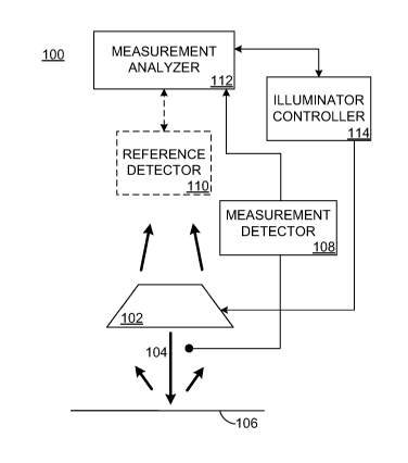
[0013] FIGURE 1 illustrates a first example color
measurement system for measuring color according to one
embodiment of this disclosure;
[0014] FIGURE 2 illustrates a second example color
measurement system for measuring color according to one
embodiment of this disclosure;
[0015] FIGURE 3 illustrates a third example color
measurement system for measuring color according to one
embodiment of this disclosure;
[0016] FIGURES 4A and 4B illustrate a first example
method for measuring color according to one embodiment of
this disclosure;
[0017] FIGURES 5A and 5B illustrate a second example
method for measuring color according to one embodiment of
this disclosure;
[0018] FIGURE 6 illustrates a fourth example color
measurement system for measuring color according to one
embodiment of this disclosure;
[0019] FIGURE 7 illustrates a fifth example color
measurement system for measuring color according to one
embodiment of this disclosure; and
[0020] FIGURE 8 illustrates a third example method for
measuring color according to one embodiment of this
disclosure.
CA 02669859 2009-05-15
WO 2008/064098 PCT/US2007/084907
6
DETAILED DESCRIPTION
[0021] FIGURE 1 illustrates a first example color
measurement system 100 for measuring color according to one
embodiment of this disclosure. The embodiment of the color
measurement system 100 shown in FIGURE 1 is for
illustration only. Other embodiments of the color
measurement system 100 could be used without departing from
the scope of this disclosure.
[0022] As shown in FIGURE 1, the color measurement
system 100 includes one or more illuminating devices 102.
Each illuminating device 102 generates and provides a light
beam 104, which illuminates at least part of a sample 106.
The light beam 104 could have any suitable wavelength or
range of wavelengths, such as light within a visible range
or an ultraviolet range. As a particular example, the
light beam 104 could represent a collimated beam of light.
The illuminating device 102 includes any suitable structure
for generating light.
[0023] In some embodiments, an illuminating device 102
includes one or more light emitting diodes (LEDs). The
LEDs may emit light at one or more wavelengths or
wavelength ranges, and the LEDs may emit light in a
continuous or intermittent manner. In particular
embodiments, multiple LEDs can be used in an illuminating
device 102, and the LEDs may or may not emit light having
different spectrums. When multiple LEDs are used,
individual LEDs can be illuminated (possibly independent of
other LEDs) to control the wavelength spectrum of light
emitted by the illuminating device 102. The LEDs could
represent any suitable light emitting diode or diodes, such
as large surface area LEDs formed from arrays of miniature
LEDs in a honeycomb structure. The LEDs could also support
CA 02669859 2009-05-15
WO 2008/064098 PCT/US2007/084907
7
individually controlled wavelength bands, such as red-
green-blue LEDs. The LEDs could further represent
broadband emitters, such as those constructed using
multiple phosphors or incorporating quantum dots.
[0024] In these embodiments, an illuminating device 102
could include additional components in addition to the
LEDs. For example, the illuminating device 102 could
include heat sink panels, optical elements, one or more
circuit boards on which the LEDs are mounted, and
mechanical arrangements for mounting the device 102. The
optical elements may include beam-shaping optics, such as
micro-lenses, micro-reflectors, micro-diffusers, and
spectral filters. The illuminating device 102 could be
configured to allow for the replacement of part or all of
the illuminating device 102 at regular intervals or when
needed (such as when diagnostic tests indicate degraded
performance). Different illuminating devices 102 may have
different LED types and combinations.
[0025] The light beam 104 generated by the illuminating
device 102 is directed at the sample 106. The sample 106
may represent any suitable portion of a material or
materials being analyzed, such as a material where the
color or other spectral properties are being determined.
The sample 106 could represent a variety of materials
handled in a manufacturing, mechanized, or other process.
Example samples 106 could include a web of paper or board,
a sheet or film of plastic, or a woven or non-woven fabric.
A web of material could be continuously moved throughout a
process (such as a paper production or printing process)
using rollers, presses, and other machinery. The sample
106 could be transparent, translucent, or opaque. While
the sample 106 may be described in this document as a sheet
or web of paper, the sample 106 is not limited to sheets or
CA 02669859 2009-05-15
WO 2008/064098 PCT/US2007/084907
8
webs of paper. Also, a sample 106 representing a sheet of
material could represent an individual sheet of material
that is advanced on a conveyor belt or other device(s) for
transporting sheets of material, or the sample 106 could
represent multiple sheets of material. The sample 106
could further represent a portion of a continuous sheet of
material or a discrete sample placed manually for
measurement.
[0026] In this example embodiment, the light beam 104 is
reflected off of the sample 106 and measured by a
measurement detector 108. A portion of the light beam 104
produced by the illuminating device 102 may also be
directed to a reference detector 110, which measures the
portion of the light beam 104 from the illuminating device
102. Each of the detectors 108-110 measures light in any
suitable manner, such as by measuring the spectral power
distribution of the received light. Each of the detectors
108-110 includes any suitable structure for measuring
light, such as structures for converting collected light
into electrical charges. In some embodiments, the
detectors 108-110 may use optic fiber, micro optics, or
other mechanisms to collect light to be detected by the
detectors 108-110. Moreover, spectral filters or other
elements such as dichroic beam splitters may be used to
modify the spectral power distribution of the collected
light before it is detected. These can be used, for
instance, to exclude spectral bands that are undesirable
for a measurement detector 108 or to divide the light
between plural detectors responsive to different spectral
ranges. Also, the measurement detector 108 could measure
the spectral power distribution of light in multiple
wavelength bands substantially spanning at least the
visible light range.
CA 02669859 2009-05-15
WO 2008/064098 PCT/US2007/084907
9
[0027] The detectors 108-110 may be formed from or
represent a variety of devices, such as charge-coupled
devices (CCD), charge injection devices (CID), digital
Complementary Metal Oxide Semiconductor (CMOS) photodiode
arrays, discrete photodiodes, or any other suitable light
sensitive device(s). Output signals generated by the
detectors 108-110 may be analog or digital, such as an
analog signal converted to a digital signal for processing.
[0028] In particular embodiments, the measurement
detector 108 and the reference detector 110 could represent
spectrometers. A spectrometer may include a spectrograph
(containing a light entrance port and a dispersive element
such as a grating) and a detector. The dispersive element
could include a linear variable filter or a set of discrete
optical filters of known characteristics. The spectrometer
may have additional optical elements (such as mirrors or
beam splitters) to direct a beam of light towards the
dispersive element, distribute the beam across the
dispersive element, or focus dispersed light onto a
detector. The detector in a spectrometer could represent a
linear CCD detector with photodiodes (such as 128 to 2,048
photodiodes), a two-dimensional array of photodiodes, or a
set of discrete photodetectors. A spectrometer may isolate
an approximately collimated portion of a light beam and
disperse the light beam into multiple wavelength bands
using the dispersive element. The spectrometer may also
distribute the dispersed light onto the detector so that
specific wavelength bands are directed at or incident on
specific positions of the detector. The detector may
detect and quantify the light falling on multiple positions
of the detector and produce spectral measurements from
which colorimetric data may be derived. In other
CA 02669859 2009-05-15
WO 2008/064098 PCT/US2007/084907
particular embodiments, the detectors 108-110 could
represent spectrocolorimeters, which could produce as
output only colorimetric data (such as tristimulus values
and derived colorimetric data like brightness data).
[0029] In this example, the measurement detector 108 may
measure the spectrum of light reflected from the sample
106. The measured light represents light from the
illuminating device 102 that has illuminated the sample 106
and interacted with the sample 106 by being reflected from
the sample 106. Depending on the sample 106, the reflected
light could include fluorescent emission or phosphorescent
emission from the sample 106 in response to the
illumination.
[0030] The reference detector 110 may measure the
spectrum of light from the illuminating device 102. This
light has not interacted with the sample 106 or with a
calibration standard. The input to the reference detector
110 may represent a portion of the light beam 104 produced
by the illuminating device 102.
[0031] The measurement detector 108 and the reference
detector 110 supply the measured values of light (such as
measured spectral power distributions or weighted averages
of spectral ranges) to a measurement analyzer 112. The
measurement analyzer 112 uses the values of light from the
detectors 108-110 to determine the color of the sample 106.
However, as noted below, the reference detector 110 could
be omitted from a color measurement system, and the
measurement analyzer 112 could use values of light from
only the measurement detector 108 to determine the color of
the sample 106. For example, the measurement analyzer 112
could use measurement data from the detectors 108-110 to
determine a radiance transfer factor matrix for the sample
106, which can be used to determine the color of the sample
CA 02669859 2009-05-15
WO 2008/064098 PCT/US2007/084907
11
106 under a specified lighting condition. The measurement
analyzer 112 could use the determined color in any suitable
manner, such as comparing the determined color to a
specified color or color range (such as a desired color or
range) or outputting the determined color for use by an
external system. The measurement analyzer 112 could
include any hardware, software, firmware, or combination
thereof for determining a color of a sample 106.
[0032] An illuminator controller 114 controls the
operation of the illuminating device 102, thereby
controlling the illumination of the sample 106. Depending
on the implementation, the measurement analyzer 112 may
regulate the illuminator controller 114, such as when the
measurement analyzer 112 directs the illuminator controller
114 to cause the illuminating device 102 to emit light in
different relative intensities at each of multiple
wavelength bands. The illuminator controller 114 could
also operate independent of the measurement analyzer 112.
The illuminator controller 114 includes any hardware,
software, firmware, or combination for controlling one or
more illuminating devices, such as LEDs.
[0033] The illuminator controller 114 may control the
operation of the illuminating device 102 in any suitable
manner. For example, LEDs in the illuminating device 102
may be controlled by altering the current and/or voltage
used to drive the LEDs, which may influence the relative
spectral power distribution and/or the total power of light
emitted by the LEDs. Also, altering the duty cycle (the
percentage of time an LED is activated during a specified
period) of the LEDs can be used to alter the average
spectral power distribution of light emitted by the LEDs.
Using one or both of these techniques, the illuminator
controller 114 could control the spectral power
CA 02669859 2009-05-15
WO 2008/064098 PCT/US2007/084907
12
distribution of the light provided by the illuminating
device 102. When controlling the duty cycle of the LEDs,
the LEDs can be switched on and off at any suitable rate,
which can include the use of rapid switching such as
microsecond switching. Moreover, the instants at which
this switching takes place need not necessarily be
separated by equal time intervals. While periodic
switching at a fixed frequency may be advantageous in some
embodiments, the switching can be performed in any
arbitrary periodic or aperiodic sequence that achieves the
desired duty cycle. Also, if multiple LEDs are used, the
duty cycle of one or some of the LEDs can be varied in a
different manner than the duty cycle of one or some others
of the LEDs. In particular embodiments, the illuminator
controller 114 regulates the timing of at least one LED so
that the LED is switched on for less than an entire
measurement interval. The timing of switching the LED can
be controlled so as to achieve a desired average spectral
power distribution for illumination during that measurement
interval. The measurement interval is that time during
which the detector accumulates received light to form a
measurement. This interval need not necessarily be of a
fixed duration, and the interval can be formed by combining
detection from plural subintervals that need not
necessarily be contiguous in time.
[0034] As noted above, the color measurement system 100
may or may not include the reference detector 110. The
reference detector 110 could be omitted from the color
measurement system 100, for example, when LEDs are used in
the illuminating device 102. This is because the spectral
power distribution of light provided by LEDs may be known
ahead of time, so the reference detector 110 may not be
needed to determine the spectral power distribution of
CA 02669859 2009-05-15
WO 2008/064098 PCT/US2007/084907
13
light provided by the LEDs.
[0035] In one aspect of operation, the color measurement
system 100 may determine the color of the sample 106 by
directing the beam of light 104 at the sample 106 to
illuminate at least part of the sample 106. The color
measurement system 100 may then detect and measure the
light that has interacted with the sample 106. The
interaction of the light beam 104 with the sample 106 may
include absorption, scattering, and excitation of
fluorescent emission. The detection and measurement of
light that has interacted with the sample 106 may occur on
the same side of the sample 106 as the illumination, on the
opposite side of the sample 106 than the illumination, or
on both sides of the sample 106 (either simultaneously or
sequentially). In this example, the measurement detector
108 measures the light reflected from the sample 106 on the
same side of the sample 106 as the illumination.
[0036] The portion of the sample 106 from which light is
directed to the measurement detector 108 may be called the
"viewed area." The viewed area could represent a circular
disk with a radius of 10mm, but it may be larger or smaller
and need not be circular or contiguous. The illuminated
portion of the sample 106 could include the entire viewed
area and may include an additional area bounding the viewed
area. The illuminated portion of the sample 106 could even
include the entire sample 106. The illumination could be
spatially uniform over at least the viewed area, both in
intensity and in spectral power distribution at any
measurement instant.
[0037] The reference detector 110 may provide a
reference point for the measurement analyzer 112. The
reference detector 110 may be positioned to receive an
accurate sample of the light emitted by the illuminating
CA 02669859 2009-05-15
WO 2008/064098 PCT/US2007/084907
14
device 102. In some embodiments, the reference detector
110 may use an optical fiber to gather light directly from
the illuminating device 102 or from the edges of the beam
104. The optical fiber may prevent reflected light from
corrupting the light sample measured by the reference
detector 110. The reference detector 110 may have the same
or similar light detecting structure as the measurement
detector 108.
[0038] Depending on the configuration, the light
measured by the reference detector 110 may have essentially
the same spectral power distribution as the light provided
to the sample 106. For example, the light beam 104
produced by the illuminating device 102 can be divided
between these two purposes, but it need not be divided in
equal amounts. As particular examples, optical fibers,
optical mirrors, or achroic beam splitters may cause a
portion of the light from the illuminating device 102 to be
directed to the reference detector 110 and another portion
to be directed to illuminate the sample 106. As another
particular example, a multi-ported integrating sphere (the
internal surface of which is diffusely reflective) may be
used to combine light from the illuminating device 102,
supply a specific fraction of the combined light to the
reference detector 110, and supply another portion of the
combined light to illuminate the sample 106. Instead of a
sphere, a partial sphere or other suitable shape may also
be used, and the number and positions of light entry ports
and light exit ports can be chosen appropriately.
[0039] The illuminating device(s) 102 and the detectors
108-110 could have any suitable arrangement or geometry in
the color measurement system 100. The measurement geometry
is the geometric arrangement relative to the sample 106 of
the light incident on the sample 106 and the light from the
CA 02669859 2009-05-15
WO 2008/064098 PCT/US2007/084907
sample 106 incident on the measurement detector 108. There
are numerous measurement geometries in common use. Some
have been formalized in international standards, including
0/45, 45/0, 0/d, and d/0 arrangements. The first number in
each arrangement represents the angle (in degrees relative
to the sample 106) at which the sample 106 is to be
illuminated. The second number is the angle (in degrees
relative to the sample 106) at which light from the sample
106 is to be measured. By convention, the 00 angle in
these arrangements is taken to be perpendicular to the
sample 106 being illuminated. The designation "d"
indicates that the illumination or measurement is to be
diffuse or non-directional. For directional illumination
at angles greater than 00, the illumination may be from a
single azimuth direction, from multiple azimuth directions,
or from a circular annulus.
[0040] The measurement analyzer 112 may compare the
intensity and spectrum of light measured by the detectors
108-110 with known values of intensity and spectrum of
light for at least one calibration tile of known
properties. By illuminating at least one calibration tile
and measuring the light at both the reference detector 110
and the measurement detector 108, it is possible to form a
relation between the photometric scales of the detectors
108-110. For example, a normalizing ratio for the
detectors 108-110 can be determined for each spectral band.
After that, in measuring a sample 106, the relation
between these photometric scales can be used to obtain a
total radiance factor measurement from the measurements
made at the detectors 108-110. The total radiance factor
measurement can be used to determine the color of the
sample 106. In some embodiments, the measurement analyzer
112 may use a stored table, equations, or a combination
CA 02669859 2009-05-15
WO 2008/064098 PCT/US2007/084907
16
thereof to compute the characteristics of the sample 106.
[0041] In particular embodiments, LEDs form the
illuminating device 102, and the LEDs may be regulated so
as to produce one or more illumination states for the
measurements. The measurement analyzer 112 may determine
the characteristics of the sample 106 by determining the
ratio of the reflecting light beam intensity and/or
spectrum to the intensity and/or spectrum of the
illuminating light beam 104 from the illuminating device
102. After compensating for the relation between
photometric scales, the ratio of the light measured at the
measurement detector 108 to the light measured at the
reference detector 110 may represent the total radiance
factor of the sample 106 for the illuminator used for that
particular measurement.
[0042] The color to be determined for the sample 106 may
depend on one or more specified illumination states for the
sample 106. For example, a specification for a paper
product may define an acceptable color or color range, but
the specification may define an illumination state to be
used when determining if the actual color of the paper
product is acceptable. Depending on the implementation,
the color of the sample 106 may be determined for an
illuminator that matches an illumination state used in a
measurement. The color of the sample 106 may also be
determined for an illuminator that does not match any
illumination state used in the measurements, such as one
expressed as a linear combination of different illumination
states used in the measurements. The color of the sample
106 may further be determined for a specified illuminator
that does not match any illumination state used in the
measurements and that is not expressible exactly as a
linear combination of illumination states used in the
CA 02669859 2009-05-15
WO 2008/064098 PCT/US2007/084907
17
measurements. In this last case, the color may be
determined as belonging to an interval or range of colors
that are defined by a set of linear combinations of
illumination states used in the measurements, where the set
forms a set of perturbations approximating the specified
illuminator. The color may be determined for the sample
106 itself, for an infinitely thick opaque pad formed of
similar samples 106, for the sample 106 itself with a
backing having known optical properties, or in any other
suitable manner.
[0043] In particular embodiments, the measurement
analyzer 112 could include a processor, a memory, and one
or more input/output interface devices. A local interface
(such as a network interface) may have additional elements,
such as controllers, buffers (caches), drivers, repeaters,
and receivers that enable communications. Further, the
local interface may include address, control, and/or data
connections to enable appropriate communications among the
components of a network. The measurement analyzer 112
could also include software used with a computer or other
suitable operating device (such as the processor) . The
measurement analyzer 112 could further include or support a
graphical user interface (GUI) to enable interactions with
a user. For example, the GUI could allow an administrator
or other user to enter, view, and store the characteristics
of the sample 106 or to enter constraints for controlling
components of the color measurement system 100 or a
manufacturing process. In addition, the measurement
analyzer 112 could be separate from the other components of
the color measurement system 100 (which could collectively
form a single measurement device). The measurement
analyzer 112 is not limited just to reflectance
measurements of color and can measure transmittance
CA 02669859 2009-05-15
WO 2008/064098 PCT/US2007/084907
18
measurements of color or both characteristics
simultaneously.
[0044] Depending on the implementation, the illuminator
controller 114 may be incorporated in or governed by the
measurement analyzer 112, or it may be an autonomous unit.
The illuminator controller 114 may control the light
output from the illuminating device 102 (such as an LED or
group of LEDs) by controlling the voltage and/or current
supplied to the LED or group of LEDs. The illuminator
controller 114 may also control the light output from the
illuminating device 102 by controlling the duty cycle of
the LED or group of LEDs, such as by controlling the amount
of time that the LED or group of LEDs produces light during
a measurement. In some embodiments, the illuminating
device 102 may be operated in a continuously-on mode or in
an intermittent mode, such as in a flashing on-off mode.
In the continuously-on mode, the power for the illuminating
device 102 may be fixed or varied (such as varied as a
function of time according to a deterministic schedule or
in a random or pseudo-random sequence). In the
continuously-on mode, the illuminating device 102 may be
intermittently switched off, such as between measurement
intervals. In the flashing on-off mode, the power for the
illuminating device 102 may be fixed or varied from flash
to flash (such as varied according to a deterministic
schedule or in a random or pseudo-random sequence). The
operating mode, voltage, current, power, timing, duty
cycle, and so forth may or may not be the same for all
LEDs.
[0045] In particular embodiments, an autonomous
illuminator controller 114 operates the LEDs in a fixed
sequence of states, where each state has a specified
duration. Also, for each state, a voltage, current, duty
CA 02669859 2009-05-15
WO 2008/064098 PCT/US2007/084907
19
cycle, or power may be defined for each LED or group of
LEDs, and a timing may be defined for switching each LED or
group of LEDs on and off. For example, in a first state
lasting lOms, a first LED may be continuously on with a
current of 200mA, a second LED may be flashing on-off at
1000Hz with a flash current of 2A and a flash duration of
100ps, and a third LED may be continuously on with current
rising linearly from lOOmA to 300mA. In a second state
lasting 5ms, the first and second LEDs could both be
continuously on where each has a current of 150mA, and the
third LED can be switched off.
[0046] The illuminator controller 114 may also perform
thermal management of the LEDs, such as by monitoring their
temperatures and by operating heating or cooling devices to
keep the LED temperatures within acceptable limits. For
example, the LEDs could be heated by switching them on at
times when measurements are not being made.
[0047] The color measurement system 100 can be
calibrated from time to time, such as during a calibration
that occurs periodically or whenever possible. This may be
done, for example as described above, to determine the
relation between the photometric scales of the detectors
108-110. The calibration could include the use of one or
more calibration tiles, such as an opaque white tile with
known high reflectivity at all wavelengths of interest.
During calibration, a calibration tile could be placed in
the same position in which the sample 106 to be measured is
normally located. However, this is not a necessity if the
optical path is folded or otherwise compensated by other
means. In that case, a calibration tile could be located
elsewhere, even "inside" a measurement instrument, in a
position that is optically equivalent to the position of
the sample 106.
CA 02669859 2009-05-15
WO 2008/064098 PCT/US2007/084907
[0048] The color measurement system 100 and its various
other embodiments may comply with any of the various
standards used in the appropriate industry. These
standards could include Technical Association of the Pulp
and Paper Industry (TAPPI) standards, as well as any other
industry, government, or other standards.
[0049] FIGURE 2 illustrates a second example color
measurement system 200 for measuring color according to one
embodiment of this disclosure. The embodiment of the color
measurement system 200 shown in FIGURE 2 is for
illustration only. Other embodiments of the color
measurement system 200 could be used without departing from
the scope of this disclosure.
[0050] The color measurement system 200 is similar to
the color measurement system 100 of FIGURE 1. As shown in
FIGURE 2, the color measurement system 200 includes an
illuminating device 202 for providing a light beam 204 to
illuminate a sample 206. The illuminating device 202 may
provide a focused beam of light or collimated light beam,
such as by utilizing one or more LEDs. Reflected beams of
light are detected and measured by multiple measurement
detectors 208. The measurement detectors 208 supply
measured values of light to a measurement analyzer 212. A
reference detector 210 may be used to provide a reference
point for the measurement analyzer 212.
[0051] The measurement analyzer 212 uses the values of
light to determine the characteristics of the sample 206.
The measurement analyzer 212 may also regulate an
illuminator controller 214, which controls the illuminating
device 202. The illuminator controller 214 could also
operate independent of the measurement analyzer 212. The
illuminator controller 214 could cause the illuminating
device 202 to emit different wavelengths or intensities of
CA 02669859 2009-05-15
WO 2008/064098 PCT/US2007/084907
21
light. The components of the color measurement system 200
may incorporate aspects as previously described with
respect to the color measurement system 100 of FIGURE 1.
[0052] As noted above, the reference detector 210 may be
used to provide a reference point for the measurement
analyzer 212. The reference detector 210 may be positioned
to receive an accurate sample of the light emitted by the
illuminating device 202. In particular embodiments, the
reference detector 210 may use a trapezoid mirror and/or
other micro lens and optical components to gather light
directly from the illuminating device 202 or from the edges
of the light beam 204. The trapezoid mirror may prevent
reflected light from corrupting the reference. In other
embodiments, the reference detector 210 can be omitted from
the color measurement system 200.
[0053] In this example embodiment, the sample 206 has a
first background 216 and a second background 218. The
backgrounds 216-218 may allow the measurement analyzer 212
to determine characteristics of the sample 206 based on the
reflected light associated with the different backgrounds
216-218. For example, the backgrounds 216-218 could
represent a backing of known low reflectivity and a backing
of known high reflectivity, respectively. As a particular
example, the first background 216 may be black, and the
second background 218 may be white. In these embodiments,
the scattering, absorption, and/or fluorescent emission
spectra of the sample 206 can be inferred from simultaneous
measurements of remitted light made above the backing of
known low reflectivity and the backing of known high
reflectivity. For a translucent sample 206, reflectance
measurements with black and white backing can be utilized
with the Kubelka-Munk method to estimate true reflectance
for an infinitely thick pad formed of the sample 206. The
CA 02669859 2009-05-15
WO 2008/064098 PCT/US2007/084907
22
Kubelka-Munk method can also be extended to accommodate
fluorescence in the color estimation. This could also be
done using a measurement of remitted light above a backing
of known reflectivity and a simultaneous measurement of
transmitted light on the non-illuminated side of the sample
206 (which can be done as described below).
[0054] FIGURE 3 illustrates a third example color
measurement system 300 for measuring color according to one
embodiment of this disclosure. The embodiment of the color
measurement system 300 shown in FIGURE 3 is for
illustration only. Other embodiments of the color
measurement system 300 could be used without departing from
the scope of this disclosure.
[0055] The color measurement system 300 is similar to
the color measurement systems 100 and 200 of FIGURES 1 and
2. As shown in FIGURE 3, the color measurement system 300
includes multiple illuminating devices 302 for providing
multiple light beams 304 to illuminate a sample 306. Each
illuminating device 302 could provide a focused beam of
light or collimated light beam, such as by utilizing one or
more LEDs. In this example embodiment, the LEDs may be
located on multiple circuit boards 316. In particular
embodiments, the circuit boards 316 may include LEDs that
emit different spectrums or wavelengths of light. For
example, one circuit board 316 may include LEDs that emit
light in the visible spectrum, while another circuit board
316 may include LEDs that emit light in the ultraviolet
spectrum. The circuit boards 316 may also include LEDs
that emit light from different directions. The circuit
boards 316 may make it possible to replace LEDs without
requiring all LEDs of the color measurement system 300 to
be replaced at the same time. For example, an
administrator may replace the ultraviolet LEDs on a more
CA 02669859 2009-05-15
WO 2008/064098 PCT/US2007/084907
23
regular interval.
[0056] Reflected beams of light are detected and
measured by multiple measurement detectors 308. Each
measurement detector 308 supplies measured values of light
to a measurement analyzer 312. A reference detector 310
may be used to provide a reference point for the
measurement analyzer 312. The measurement analyzer 312
uses the values of detected light to determine the
characteristics of the sample 306. The measurement
analyzer 312 may also regulate an illuminator controller
314, or the illuminator controller 314 could operate
independently. For example, the measurement analyzer 312
may direct the illuminator controller 314 to cause the
illuminating devices 302 to emit light in different
relative intensities at each of multiple wavelength bands.
The components of the color measurement system 300 may
incorporate aspects as previously described with respect to
the color measurement systems 100 and 200.
[0057] The reference detector 310 may be positioned to
receive an accurate sample of the light emitted by
illuminating device 302. In some embodiments, the
reference detector 310 may detect light at a location
between the circuit boards 316 to gather light directly
from the illuminating device 302. In other embodiments,
the reference detector 310 may be omitted from the color
measurement system 300.
[0058] FIGURES 4A and 4B illustrate a first example
method for measuring color according to one embodiment of
this disclosure. More specifically, FIGURE 4A illustrates
an example method 400 for calibrating a color measurement
system, and FIGURE 4B illustrates an example method for
determining the color of a sample using the color
measurement system. The embodiments of the methods 400,
CA 02669859 2009-05-15
WO 2008/064098 PCT/US2007/084907
24
450 shown in FIGURES 4A and 4B are for illustration only.
Other embodiments of the methods could be used without
departing from the scope of this disclosure.
[0059] As shown in FIGURES 4A and 4B, there may be two
phases to measuring the color of a sample, a calibration
phase (shown in FIGURE 4A) in which parameters of the color
measurement system are determined and an operation phase
(shown in FIGURE 4B) in which the color measurement system
is used to measure the sample.
[0060] As shown in FIGURE 4A, in the calibration phase,
an initial power setting is selected at step 402. Power
with this setting is supplied to an illuminating device
(such as 102, 202, 302), causing the illuminating device to
produce a first beam of light (such as 104, 204, 304) at
step 404. The first beam of light is directed onto a
reference material of known properties at step 406. The
reference material may, for example, represent a diffusely
reflecting material of known high reflectance through at
least the visible range. The reference material may also
represent a fluorescent material of known fluorescence
characteristics and known reflectance in the excitation and
emission bands of its fluorescence.
[0061] A second beam of light that has interacted with
the reference material is received at step 408, and the
spectral power distribution of the received second beam is
measured at step 410. This could include using one or more
measurement detectors (such as 108, 208, 308) to measure
the spectral power distribution of light reflected from the
reference material. The spectral power distribution of the
first beam of light is determined from the measured
spectral power distribution of the second beam of light and
the known properties of the reference material at step 412.
The power setting and the determined spectral power
CA 02669859 2009-05-15
WO 2008/064098 PCT/US2007/084907
distribution of the first beam of light are stored at step
414.
[0062] The power setting is modulated so as to alter the
spectral power distribution of the first beam of light at
step 416. This could include adjusting the voltage or
current used to drive LEDs or the duty cycle of the LEDs.
The method 400 then returns to step 404 to supply power
with the new settings to the illuminating device, and steps
404-414 are repeated for the new setting. Steps 404-416
could be repeated a number of times so that a variety of
power settings and corresponding spectral power
distributions are determined and stored. The steps may be
repeated using the same or multiple reference materials,
such as reference materials having different fluorescence
characteristics.
[0063] Once the calibration phase has been performed at
least once, the color measurement system can be used in an
operation phase to determine the color of a sample. As
shown in FIGURE 4B, a desired spectral power distribution
for illumination is specified at step 452. From the stored
power settings and stored spectral power distributions
obtained in the calibration phase, a power setting is
determined that should cause the illuminating device to
produce light of the desired spectral power distribution at
step 454. A manufacturing or other process advances a
sample (such as 106, 206, 306) to the appropriate location,
such as to a pass-line of the color measurement system, at
step 456.
[0064] An illuminator controller (such as 114, 214, 314)
supplies power with the determined settings to an
illuminating device, causing it to produce a first beam of
light of the desired spectral power distribution at step
458. This may be accomplished by supplying power to
CA 02669859 2009-05-15
WO 2008/064098 PCT/US2007/084907
26
selected LEDs of the illuminating device. The power could
have a specified voltage and/or current level, or the power
could have a specified duty cycle.
[0065] The illuminating device directs the first beam of
light onto the sample at step 460. The first beam of light
interacts with the sample to produce a second beam of
light, which is received by at least one measurement
detector at step 462. The at least one measurement
detector measures the spectral power distribution of the
received second beam of light at step 464. A measurement
analyzer (such as 112, 212, 312) determines the
characteristics of the sample from the spectral power
distribution of the second beam of light at step 466. If
necessary, the measurement analyzer may change the desired
spectral power distribution for illumination during
operation and may employ measurements made by illuminating
the sample with a single spectral power distribution or
with each of two or more spectral power distributions in
determining characteristics of the sample.
[0066] The calibration phase may be repeated from time
to time, for example, so that the effects of component
aging can be compensated for and performance degradation
can be avoided. In particular embodiments, one or more
suitable reference materials may be contained within the
measurement apparatus with a mechanism that deploys it/them
into the measurement position or that alters the light path
of the first and second light beams so that the calibration
can be performed with minimal disturbance to normal
operation.
[0067] Although FIGURES 4A and 4B illustrate one example
of a method for measuring color, various changes may be
made to FIGURES 4A and 4B. For example, while shown as a
series of steps, various steps in FIGURES 4A and 4B could
CA 02669859 2009-05-15
WO 2008/064098 PCT/US2007/084907
27
overlap or occur in parallel. As a particular example,
steps 452 and 456 could occur in parallel with step 454.
Also, although not shown, the color measurement system
could use a reference detector (such as 110, 210, 310)
during calibration or during normal operation. In
addition, both methods could involve the use of one or
multiple illuminating devices or measurement detectors.
[0068] FIGURES 5A and 5B illustrate a second example
method 500 for measuring color according to one embodiment
of this disclosure. The embodiment of the method 500 shown
in FIGURES 5A and 5B is for illustration only. Other
embodiments of the method could be used without departing
from the scope of this disclosure.
[0069] A manufacturing or other process advances a
sample to the appropriate location in a color measurement
system at step 502. A desired spectral power distribution
for illumination is selected at step 504. An initial power
setting for the desired spectral power distribution is
selected at step 506. An illuminator controller supplies
power with the given power setting to an illuminating
device, causing it to produce a beam of light at step 508.
[0070] The beam of light is divided into a first beam
and a second beam at step 510. The first beam and the
second beam need not have the same total power, but their
relative spectral power distributions could be the same at
least in the visible range. The second beam of light is
directed onto a reference detector (such as 110, 210, 310)
at step 512. The reference detector measures the spectral
power distribution of the second beam as a reference
spectral power distribution at step 514.
[0071] The illuminator controller modulates the power
setting of the illuminating device so as to minimize the
difference between the measured reference spectral power
CA 02669859 2009-05-15
WO 2008/064098 PCT/US2007/084907
28
distribution and the desired spectral power distribution at
step 516. Steps 508-516 could then be repeated until the
difference between the measured reference spectral power
distribution and the desired spectral power distribution is
sufficiently small (such as within a specified threshold).
These steps could also be repeated whenever the illuminator
controller selects a different desired spectral power
distribution for illumination. The steps may further be
repeated from time to time during operation to ensure that
the spectral power distribution used for illumination does
not deviate from the desired spectral power distribution.
[0072] The first beam of light is directed onto the
sample at step 518. A third beam of light, which has
interacted with the sample, is received by a measurement
detector at step 520. The measurement detector measures
the spectral power distribution of the received third light
beam, producing a measured spectral power distribution at
step 522. When the reference spectral power distribution
is sufficiently close to the desired spectral power
distribution, the characteristics of the sample can be
determined from the measured spectral power distribution by
a measurement analyzer at step 524. The measurement
analyzer may change the desired spectral power distribution
for illumination during operation and may employ
measurements made by illuminating the sample with a single
desired spectral power distribution or with each of
multiple desired spectral power distributions in
determining characteristics of the sample. The power
setting that minimizes the difference between the reference
spectral power distribution and the desired spectral power
distribution can be stored by the measurement analyzer or
by the illuminator controller for later use. A stored
power setting for a desired spectral power distribution can
CA 02669859 2009-05-15
WO 2008/064098 PCT/US2007/084907
29
be used as an initial power setting if the measurement
analyzer selects the same desired spectral power
distribution at a later time.
[0073] Although FIGURES 5A and 5B illustrate another
example of a method for measuring color, various changes
may be made to FIGURES 5A and 5B. For example, while shown
as including both series and parallel steps, various steps
in FIGURES 5A and 5B could be rearranged into serial or
parallel steps. As a particular example, steps 518-524
could occur in series with step 516, such as after step 516
has modulated the power supply to an acceptable setting.
Also, while shown as using a reference detector, the color
measurement system could omit the use of a reference
detector. In addition, the method 500 could involve the
use of one or multiple illuminating devices or measurement
detectors.
[0074] FIGURE 6 illustrates a fourth example color
measurement system 600 for measuring color according to one
embodiment of this disclosure. The embodiment of the color
measurement system 600 shown in FIGURE 6 is for
illustration only. Other embodiments of the color
measurement system 600 could be used without departing from
the scope of this disclosure.
[0075] The color measurement system 600 is similar to
the color measurement systems 100-300 of FIGURES 1-3. As
shown in FIGURE 6, the color measurement system 600
includes an illuminating device 602 for providing a light
beam 604 to illuminate a sample 606. The illuminating
device 602 may provide a focused beam of light or
collimated light beam, such as by utilizing one or more
LEDs.
[0076] The light transmitted through the sample 606 is
detected by a measurement detector 608. In this example,
CA 02669859 2009-05-15
WO 2008/064098 PCT/US2007/084907
the measurement detector 608 may be located or measure the
light behind the sample 606 with respect to the
illumination of the sample 606. The measurement detector
608 supplies measured values of light to a measurement
analyzer 612. A reference detector 610 may be used to
provide a reference point for the measurement analyzer 612.
The measurement analyzer 612 uses the values of detected
light to determine the characteristics of the sample 606.
The measurement analyzer 612 may also regulate an
illuminator controller 614, or the illuminator controller
614 could operate independently. The measurement analyzer
612 may direct the illuminator controller 614 to cause the
illuminating device 602 to emit light in different relative
intensities at each of multiple wavelength bands. The
components of the color measurement system 600 may
incorporate aspects as described above for the other color
measurement systems. In this example, the reference
detector 610 may be positioned to receive an accurate
sample of the light emitted by the illuminating device 602.
In other embodiments, the reference detector 610 could be
omitted from the color measurement system 600.
[0077] FIGURE 7 illustrates a fifth example color
measurement system 700 for measuring color according to one
embodiment of this disclosure. The embodiment of the color
measurement system 700 shown in FIGURE 7 is for
illustration only. Other embodiments of the color
measurement system 700 could be used without departing from
the scope of this disclosure.
[0078] The color measurement system 700 is similar to
the color measurement systems described above. As shown in
FIGURE 7, the color measurement system 700 includes an
illuminating device 702 for providing a light beam 704 to
illuminate a sample 706. The illuminating device 702 may
CA 02669859 2009-05-15
WO 2008/064098 PCT/US2007/084907
31
provide a focused beam of light or collimated light beam,
such as by utilizing one or more LEDs. A reflected beam of
light is detected by a measurement detector 708. The
measurement detector 708 supplies measured values of light
to a measurement analyzer 712. The measurement analyzer
712 may determine the color of the sample 706 and may or
may not control an illumination controller 714.
[0079] As shown here, no reference detector is used in
the color measurement system 700. In this embodiment, the
radiance transfer factor matrix used to determine the color
of the sample 706 can be computed from multiple
measurements with a range of illumination states. This can
be done without a reference detector if the illumination
states used for computing the radiance transfer factor
employ LEDs only since the spectral power distribution of
illumination is known deterministically from the operating
parameters of the LEDs. In particular embodiments, the set
of illumination states used can be chosen so as to allow
the most reliable, statistically most accurate (highest
confidence), or statistically most robust (lowest
sensitivity to perturbation) estimate of the expected
radiance transfer factor from a given number of
measurements.
[0080] In particular embodiments, the measurement
analysis methods disclosed in U.S. Patent Application No.
09/957,085 (which is hereby incorporated by reference) can
be used for computation of various properties from
measurements with multiple illumination states. For
example, an illuminator-independent radiance transfer
factor may be computed from measurements with a sufficient
number of illumination states. The total radiance factor,
fluorescent emission spectrum, and colorimetric quantities
for any specified illumination states may be computed from
CA 02669859 2009-05-15
WO 2008/064098 PCT/US2007/084907
32
this radiance transfer factor. Moreover, indices of color
inconstancy or indices of metamerism between two or more
specified illumination states may also be computed from
this radiance transfer factor. These methods can be used
with or without a reference detector since, if all
illumination in an illumination state is achieved using
LEDs, the illumination spectrum for that state can be known
without using a reference detector.
[0081] Although FIGURES 1-3, 6, and 7 illustrate various
examples of different color measurement systems for
measuring color, various changes may be made to these
figures. For example, a combination of the systems from
these figures could be used. As a particular example, a
system could include multiple measurement detectors in
front and behind a sample, with or without one or more
backgrounds. Also, various components in the color
measurement systems can be combined, further subdivided, or
omitted and additional components could be added according
to particular needs. As an example, the measurement
analyzer could be integrated with the illuminator
controller into a single functional unit.
[0082] FIGURE 8 illustrates a third example method 800
for measuring color according to one embodiment of this
disclosure. The embodiment of the method 800 shown in
FIGURE 8 is for illustration only. Other embodiments of
the method 800 could be used without departing from the
scope of this disclosure.
[0083] A manufacturing or other process advances a
sample to the appropriate position of a color measurement
system at step 802. A desired spectral power distribution
for illumination is selected at step 804.
[0084] A duty cycle for one or more illuminating devices
is determined for providing the desired spectral power
CA 02669859 2009-05-15
WO 2008/064098 PCT/US2007/084907
33
distribution at step 806. This could include an
illuminator controller determining the duty cycle of a
power supply signal, control signal, or other signal
provided to one or more LEDs. For example, a desired
average spectral power distribution can be achieved during
a measurement interval by operating an LED so that it is
switched on for less than the whole measurement interval.
The desired average spectral power distribution can also be
achieved during a measurement interval by operating
multiple LEDs so that they are not all switched on for the
same amount of time during the measurement interval.
[0085] A signal is provided to one or more illuminating
devices based on the identified duty cycle at step 808.
This could include the illuminator controller providing a
power supply signal, control signal, or other signal to one
or more LEDs in the illuminating device. The illuminating
device generates a beam of light using the signal from the
illuminator controller at step 810. One or more
characteristics of the sample being tested are determined
using the beam of light at step 812. This could include a
measurement analyzer using measurements from one or more
measurement detectors that measure light reflected or
transmitted by the sample. Measurements from a reference
detector may or may not be needed.
[0086] In this way, one or more LEDs can be operated
with a duty cycle of less than 100% relative to a
measurement interval. Also, multiple LEDs could be used
and need not all have the same duty cycle relative to the
measurement interval. Regulating the relative duty cycle
of an LED to achieve a desired average spectral power
distribution during a measurement interval can be used
additionally or alternatively to regulating the LED's
voltage and/or current or otherwise controlling its light
CA 02669859 2009-05-15
WO 2008/064098 PCT/US2007/084907
34
intensity.
[0087] Although FIGURE 8 illustrates yet another example
of a method for measuring color, various changes may be
made to FIGURE 8. For example, while shown as a series of
steps, various steps in FIGURE 8 could overlap or occur in
parallel. As a particular example, step 802 could occur in
parallel with steps 804-806. Also, the method 800 could
involve the use of one or multiple illuminating devices or
measurement detectors.
[0088] In some embodiments, various functions described
above are implemented or supported by a computer program
that is formed from computer readable program code and that
is embodied in a computer readable medium. The phrase
"computer readable program code" includes any type of
computer code, including source code, object code, and
executable code. The phrase "computer readable medium"
includes any type of medium capable of being accessed by a
computer, such as read only memory (ROM), random access
memory (RAM), a hard disk drive, a compact disc (CD), a
digital video disc (DVD), or any other type of memory.
[0089] It may be advantageous to set forth definitions
of certain words and phrases used throughout this patent
document. The term "program" refers to one or more
computer programs, software components, sets of
instructions, procedures, functions, objects, classes,
instances, related data, or a portion thereof adapted for
implementation in a suitable computer code (including
source code, object code, or executable code). The terms
"include" and "comprise," as well as derivatives thereof,
mean inclusion without limitation. The term "or" is
inclusive, meaning and/or. The phrases "associated with"
and "associated therewith," as well as derivatives thereof,
may mean to include, be included within, interconnect with,
CA 02669859 2009-05-15
WO 2008/064098 PCT/US2007/084907
contain, be contained within, connect to or with, couple to
or with, be communicable with, cooperate with, interleave,
juxtapose, be proximate to, be bound to or with, have, have
a property of, or the like. The term "controller" means
any device, system, or part thereof that controls at least
one operation. A controller may be implemented in
hardware, firmware, software, or some combination of at
least two of the same. The functionality associated with
any particular controller may be centralized or
distributed, whether locally or remotely.
[0090] While this disclosure has described certain
embodiments and generally associated methods, alterations
and permutations of these embodiments and methods will be
apparent to those skilled in the art. Accordingly, the
above description of example embodiments does not define or
constrain this disclosure. Other changes, substitutions,
and alterations are also possible without departing from
the spirit and scope of this disclosure, as defined by the
following claims.