Note: Descriptions are shown in the official language in which they were submitted.
CA 02669992 2010-11-18
DRAIN SYSTEM FOR A WAREWASHER
TECHNICAL FIELD
[0002] This application relates generally to pass through type warewasher
systems
which are used in commercial applications such as cafeterias and restaurants
and, more
particularly, to such a warewash system including a drain system having
combined drain
and pump intake.
BACKGROUND
[0003] Commercial warewashers commonly include a housing area which defines
washing and rinsing zones for dishes, pots pans and other wares. In certain
zones, water is
typically pumped from a tank through a pump intake, delivered to the wares via
a spraying
operation and collected in the tank for re-use. Occasionally, the water is
drained from the
tank through a drain for a cleaning operation. The drain may be separate from
the pump
intake.
SUMMARY
[0004] In an aspect, a warewasher for washing wares includes a chamber for
receiving wares. The chamber has an associated liquid delivery system for
spraying liquid
onto wares within the chamber. A tank collects the sprayed liquid. A liquid
recirculation
system moves liquid from the tank back to the liquid delivery system. A drain
system is
located within the tank. The drain system includes a well, a liquid
recirculation system
inlet within the well and a drain opening within the well. A drain control
assembly
includes a drain stopper member and a strainer connected with the drain
stopper member.
When the drain stopper member is positioned to block flow through the drain
opening, the
strainer is positioned to block passage of tableware into the well. The
strainer is mounted
for sliding movement along a length of the drain stopper member enabling, when
the drain
stopper member is raised slightly to permit flow out of the drain opening, the
strainer to
remain in position to block passage of tableware into the well.
[0005] In another aspect, a method of operating a warewasher is provided. The
method includes delivering a liquid to a chamber of the warewasher using a
liquid delivery
system. The liquid is received in a tank located below the chamber. Draining
of the liquid
1
CA 02669992 2009-05-15
WO 2008/067352 PCT/US2007/085711
in the tank through a drain opening of a drain system is prevented using a
plug portion of a
drain control assembly located within a drain body of the drain system. Liquid
is filtered
through a strainer of the drain control assembly as the liquid enters the
drain body. The
strainer is moveable relative to the drain control assembly while being
connected thereto.
The liquid is recirculated using a liquid recirculation system including a
liquid recirculation
inlet in communication with the drain body. The liquid recirculation system
delivers liquid
to the liquid delivery system.
[0006] In another aspect, a warewasher for washing wares includes a chamber, a
liquid delivery system configured to deliver liquid to the chamber and a tank
at the bottom
of the chamber for collecting liquid. A liquid recirculation system is
configured to move
liquid from the tank to the liquid delivery system. A drain system includes a
drain body
that receives liquid from the tank, a recirculation system inlet through which
liquid can be
drawn from the drain body and a drain opening through which liquid can be
drained from
the drain body. A drain control assembly includes a support member and a
strainer
slidingly supported by the support member such that the strainer moves
relative to the
support member. The drain control assembly is configured to be located at the
drain
system such that the strainer strains liquid flowing into the drain body.
[0007] The details of one or more embodiments are set forth in the
accompanying
drawings and the description below. Other features, objects, and advantages
will be
apparent from the description and drawings, and from the claims.
BRIEF DESCRIPTION OF THE DRAWINGS
[0008] Fig. 1 is a diagrammatic side, section view of an embodiment of a
warewash
system;
[0009] Figs. 2 and 3 are side, section views of an embodiment of a drain
system in
a closed configuration for use with the warewash system of Fig. 1;
[0010] Figs. 4 and 5 are side, section views of the drain system of Figs. 2
and 3 in
an open configuration;
[0011] Figs. 6-10 are various views of another embodiment of a drain system;
[0012] Figs. 11 and 12 illustrate operation of a system for use in opening and
closing the drain system;
[0013] Figs. 13 and 14 are side, section views of another embodiment of a
drain
system in closed and open configurations; and
[0014] Fig. 15 is a perspective view of another embodiment of a warewasher.
2
CA 02669992 2009-05-15
WO 2008/067352 PCT/US2007/085711
DETAILED DESCRIPTION
[0015] Referring to Fig. 1, an exemplary conveyor-type warewash system,
generally designated 10, is shown. Warewash system 10 can receive racks 12 of
soiled
wares 14 from an input side 16 which are moved through tunnel-like chambers
from the
input side toward a dryer unit 18 at an opposite end of the warewash system by
a suitable
conveyor mechanism 20. Either continuously or intermittently moving conveyor
mechanisms or combinations thereof may be used, depending, for example, on the
style,
model and size of the warewash system 10. The racks 12 of soiled wares 14
enter the
warewash system 10 through a flexible curtain 22 into a pre-wash chamber or
zone 24
where sprays of liquid from upper and lower pre-wash manifolds 26 and 28 above
and
below the racks, respectively, function to flush heavier soil from the wares.
The liquid for
this purpose comes from a tank 30 via a pump 32 and supply conduit 34. As will
be
described below, a drain system 36 provides a single location where liquid is
pumped from
the tank 30 using the pump 32 and where liquid can be drained from the tank,
for example,
for a tank cleaning operation.
[0016] The racks proceed to a next curtain 38 into a main wash chamber or zone
40, where the wares are subject to sprays of cleansing liquid from upper and
lower wash
manifolds 42 and 44 with spray nozzles 47 and 49, respectively, these sprays
being
supplied through a supply conduit 46 by a pump 48, which draws from a main
tank 50. A
heater 58, such as an electrical immersion heater provided with suitable
thermostatic
controls (not shown), maintains the temperature of the cleansing liquid in the
tank 50 at a
suitable level. Not shown, but which may be included, is a device for adding a
cleansing
detergent to the liquid in tank 50. During normal operation, pumps 32 and 48
are
continuously driven, usually by separate motors, once the warewash system 10
is started
for a period of time.
[0017] The warewash system 10 may optionally include a power rinse chamber or
zone (not shown) that is substantially identical to main wash chamber 40. In
such an
instance, racks of wares proceed from the wash chamber 40 into the power rinse
chamber,
within which heated rinse water is sprayed onto the wares from upper and lower
manifolds.
[0018] The racks 12 of wares 14 exit the main wash chamber 40 through a
curtain
52 into a final rinse chamber or zone 54. The final rinse chamber 54 is
provided with
upper and lower spray heads 56, 58 that are supplied with a flow of fresh hot
water via pipe
60 under the control of solenoid valve 62. A rack detector 64 is actuated when
rack 12 of
3
CA 02669992 2009-05-15
WO 2008/067352 PCT/US2007/085711
wares 14 is positioned in the final rinse chamber 54 and through suitable
electrical controls,
the detector causes actuation of the solenoid valve 62 to open and admit the
hot rinse water
to the spray heads 56, 58. The water then drains from the wares into tank 50.
The rinsed
rack 12 of wares 14 then exit the final rinse chamber 54 through curtain 66,
moving into
dryer unit 18.
[0019] Referring now to Figs. 2 and 3, drain system 36 is shown in a closed
configuration where liquid is prevented from draining from the tank 30, for
example, to
maintain liquid level within the tank. A drain control assembly 51 includes a
cylindrical
pump strainer 70 (e.g., formed of stainless steel or other suitable material
such as plastic)
that overlies a drain body or well 72 and a plug portion or stopper 74 that,
in the illustrated
closed configuration, prevents liquid from flowing from the well through a
drain port 76.
A pump intake 78 (in the illustrated case, an opening in the well sidewall) is
in
communication with the well 72 for allowing the pump 32 to draw strained
liquid from the
well during use. With the drain system 36 in the closed position, pump
strainer 70 is seated
against an upper tank surface 77 about the periphery of the well 72, to limit
ingress of large
items that could be pulled into the pump intake, and the stopper 74 is seated
against a
bottom surface 79 of the well 72, forming a seal that prevents liquid from
exiting the well
through the drain port 76.
[0020] A lever system 80 is provided so that the drain control assembly 51 can
be
moved from the closed configuration to an open configuration illustrated by
Figs. 4 and 5.
The pump strainer 70 and stopper 74 are connected to each other by an outer
stalk 82.
Outer stalk 82 includes a bore 84 that receives an inner stalk 86, which is
connected to a
lever arm 88. Lever arm 88 can be pivoted in the direction of arrow 90 from
the position
illustrated in Figs. 2 and 3 to the position illustrated in Figs. 4 and 5
using pull bar 92. At
one end, pull bar 92 includes a slot 94 that receives a projection 96 that is
sized to slide
within the slot. At an opposite end, pull bar 92 includes a handle 98 that is
graspable by a
user to allow the user to pull the pull bar away from the drain which causes
the stopper 74
and pump strainer 70 to raise (e.g., about one inch). With the drain system 36
in the open
position, liquid including sediment and food particles can flow beneath the
pump strainer
70, into the well 72 and out the drain port 76. Typically, the pump 32 is
turned off so that
particles will not flow into the pump with the drain system 36 in the open
configuration. In
some embodiments, bottom 101 is slanted downwardly toward the drain system 36
to
facilitate movement of particles toward the drain system with the drain system
in the open
4
CA 02669992 2009-05-15
WO 2008/067352 PCT/US2007/085711
configuration.
[0021] A solenoid 100 is used to maintain the pull bar 92 in the open
configuration.
The pull bar 92 is spring biased toward the closed configuration. To place the
drain system
36 in the closed configuration, a trigger 102 is actuated which actuates the
solenoid 100
and allows the pull bar 92 to move under the force of a spring to the closed
position
illustrated by Figs. 2 and 3. While the spring is not shown in Figs. 2-5, it
could be located
in chamber 103 (see spring element 105 of Figs. I 1 and 12). In some
embodiments, a
position sensor 104 (e.g., an electronic eye) is used to monitor the position
of the pull bar
92. Sensor 104 may be connected to a controller that determines when the drain
system 36
is opened. The controller may be capable of controlling pump 32, for example,
so that
when the drain system 36 is in the open configuration, the pump is
automatically turned
off. As another example, the controller may provide an indication to the user
that the drain
system 36 is in the open configuration. Pull bar 92 and handle 98 provide easy
access to
the user to open and close the drain from a location outside the tank 30. In
some
embodiments, the pump strainer and stopper can be removed from the inner stalk
86, for
example, to remove them from the tank 30.
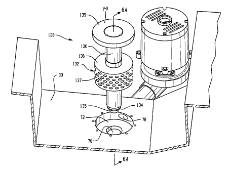
[0022] Figs. 6-10 illustrate an alternative drain system embodiment 120 for
use
with the tank 30 including pump inlet 78 and drain port 76 that are both in
communication
with well 72. A drain control assembly 128 is used to control draining of
liquid from the
tank 30. The drain control assembly 128 includes a support member (e.g., in
the form of a
standpipe 130) that supports a strainer 132 thereon. Fig. 6 illustrates the
drain control
assembly 128 removed from the well 72. A drain plug portion 134 is located at
an end of
the standpipe 130, which can be positioned within the drain port 76 to prevent
liquid from
passing thereby. The drain plug portion 134 includes a tapered end 135 that is
used to
guide the drain plug portion into the drain port 76.
[0023] Referring briefly to Fig. 6A, the standpipe 130 includes an opening 131
extending from an upper end 133 of the standpipe through the tapered end 135.
A deflector
141 may be included that is connected at the upper end 133 to the standpipe
130. The
deflector 141 is spaced from the upper end 133 to allow liquid to pass
therebetween during
an overflow condition. The deflector 141 prevents large food particles and
tableware (or
other objects) from entering the opening 131.
[0024] Referring back to Fig. 6, the strainer 132 includes a wall 137 that
extends
about the standpipe 130 (e.g., in a cylindrical manner). The wall 137 includes
openings
CA 02669992 2009-05-15
WO 2008/067352 PCT/US2007/085711
through which liquid can pass while preventing passage of particles (e.g.,
large food
particles) or other items such as tableware (e.g., knives, spoons, forks,
etc.) thereby. A
solid upper wall 136 covers a top of the wall 137. The upper wall 136 includes
an opening
sized to slidingly receive the standpipe 130. Other strainer shapes and
configurations are
contemplated. The upper wall 136 may also include strainer openings.
[0025] Referring now to Fig. 7, the strainer 132 and standpipe 130 are
moveable
relative to each other. Fig. 7 (and Fig. 6A) illustrates the strainer 132 in
its fully lowered
position, while Fig. 6 shows the strainer in its fully raised position
relative to the standpipe
130. In some embodiments, the deflector 141 is at a height hl relative to the
bottom end of
the standpipe 130 that is greater than about two times (e.g., about three
times or more) a
height h2 of the top of the strainer 132 from the bottom end of the standpipe
130 with the
strainer at its fully lowered position (see Fig. 6A). Referring to Fig. 8, as
the drain control
assembly 128 is lowered into the well 72, the strainer 132 rests on the bottom
surface of the
tank 30. The combination of the tank surface and strainer 132 prevents passage
of
potentially obstructing items into the well 72.
[0026] Fig. 9 illustrates the drain control assembly 128 in a configuration to
allow
strained liquid to drain through the drain port 76. In this configuration, the
drain plug
portion 134 of the standpipe 130 is lifted away from the drain port 76. The
standpipe 130
may be lifted mechanically into this position and/or manually. As can be seen,
in this
position, the strainer 132 remains seated against the bottom of the tank 30.
Thus, a user
can effect tank draining by lifting the standpipe 130 slightly, without
lifting the strainer 132
from its blocking position.
[0027] To prevent draining of liquid through the drain port 76, the standpipe
130
and drain plug portion 134 are lowered relative to the strainer 132. A seal
member 136
(e.g., an O-ring) is provided on the drain plug portion 134 to provide a seal
between the
drain port 76 and the drain plug portion. With the drain plug portion 134
sealed with the
drain port 76, filtered liquid can be drawn into the recirculation system from
the well 72
and provided to the liquid delivery system while liquid is prevented from
draining from the
tank through the drain port. As can also be seen in Fig. 9, a stop 137 (e.g.,
a snap ring) is
located on the standpipe 130 to prevent the strainer 132 from sliding thereby
and off of the
standpipe, for example, when the drain control assembly 128 is removed from
the well 72
(e.g., for a cleaning operation). The stop 137 is located far enough down on
the standpipe
130 to allow the standpipe to be removed from the drain port 76 while the
strainer 132
6
CA 02669992 2009-05-15
WO 2008/067352 PCT/US2007/085711
remains seated against the bottom of the tank. The stop 137 may be removable
to facilitate
separation of the strainer 132 from the standpipe 130. There may be another
stop located
above the strainer 132 on the standpipe 130 to prevent the strainer from being
raised off of
the standpipe. In the head 139 of the standpipe there is an enlarged end that
can act as a
stop. Fig. 10 shows the strainer 132 in a raised position with the drain plug
portion 134
located in the drain port 76.
[0028] Referring again to Fig. 9, in some embodiments, a tube member 138 is
connected to the upper wall 136 of the strainer 132. The tube member 138
includes an
opening through which the standpipe 130 extends. The tube member 138 interacts
with the
standpipe 130 to provide lateral stabilization of the strainer 132 on the
standpipe. The
opening of the tubular member 138 or may be free sliding.
[0029] The drain system embodiment of Figs. 6-10 is an assembly that is
arranged
to be manually inserted and removed. However, such an assembly could be linked
with a
mechanical system (such as those described herein) for triggering tank drain
operations.
[0030] Figs. 11 and 12 illustrate an example of a drain lift linkage 140 for
use in
lifting an lowering the standpipe 130. The drain lift linkage 140 includes a
support bracket
142 that is mounted on an upper surface 144 of a pump housing 146. The support
bracket
142 slidably supports a moveable member 148 that includes a pair of L-shaped
slots 150
and 152 within which fasteners 154 and 156 are received. The moveable member
148
includes an engageable end 160 that includes a graspable portion 162 that can
be grasped
and pulled by an operator to lift the moveable member and pull the moveable
member
toward the operator. Due to the L-shape of the slots 150 and 152, the moveable
member
148 can remain in the raised position until a horizontal force is applied
thereto. The
moveable member 148 is connected to a connector 164 that connects the
standpipe 130 to
the moveable member. In particular, the connector 164 is illustrated as being
releasably
engaged with the deflector 141, however, other configurations are possible.
[0031] Fig. 11 illustrates the standpipe 130 positioned in the raised position
by the
drain lift linkage 140. The slots 150 and 152 are sized such that moveable
member 148 can
be raised only so high (e.g., about 3/4 inch) as to lift the standpipe 130
from the drain port
76 to allow liquid to pass therethrough while the strainer 132 remains seated
against the
bottom of the tank 30.
[0032] Fig. 12 illustrates the standpipe 130 in the lowered position, blocking
the
drain port 76. To place the standpipe 130 in the lowered position from the
raised position,
7
CA 02669992 2009-05-15
WO 2008/067352 PCT/US2007/085711
an operator can exert a horizontal force on the moveable member 148 thereby
aligning the
fasteners 154 and 156 with the vertical portions of the slots 150 and 152. The
weight of the
standpipe 130 causes the standpipe and the moveable member 148 to drop,
thereby locating
the standpipe within the drain port 76. In one embodiment, door 166 includes a
ledge 168
that extends outwardly from the door. The ledge 168 is sized and positioned so
as to
contact the graspable portion 162 with the moveable member 148 in the raised
position and
the door 166 closed to apply the horizontal force to the moveable member to
cause the
standpipe to lower into its lowered position. This can prevent the standpipe
130 from being
in the raised position if the door 166 is closed. The ledge 168 may also be
sized so that is
does not contact the graspable portion 162 with the moveable member 148 in its
lowered
position. The standpipe 130 and strainer 132 assembly can be removed from the
drain port
76 for cleaning.
[0033] The above-described drain systems and drain control assemblies can
provide
a number of advantages. For example, by locating both the pump intake 78 and
drain port
76 within a single well, cleaning of the warewasher 10 can be simplified.
Additionally,
locating the pump intake 78 at the drain port 76 places the pump intake below
the bottom
of the tank 30 thereby increasing the head above the intake. This increase in
head above
the pump intake 78 can improve performance of the pump 32.
[0034] It is to be clearly understood that the above description is intended
by way
of illustration and example only and is not intended to be taken by way of
limitation, and
that changes and modifications are possible. For example, a foot pedal may be
used to
open and close the drain system. Figs. 13 and 14 show an alternative strainer
106 that is
cone-shaped. Additionally, the drain systems (represented by the dotted lines)
can be
utilized in other non-conveyor type machines, such as warewasher 110
illustrated by Fig.
15 or an undercounter warewasher. Accordingly, other embodiments are
contemplated and
modifications and changes could be made without departing from the scope of
this
application.
[0035] What is claimed is:
8