Note: Descriptions are shown in the official language in which they were submitted.
CA 02670169 2009-06-22
Observation device
The invention relates to an observation device comprising an
electronic display for providing additional information.
Efficient observation devices are used in particular for
military and geodetic purposes. It is important that the
devices be manageable, fast and easy to operate and as
compact and light as possible. While it was previously
usual to use a plurality of devices for different purposes,
combined, multifunctional devices are preferably used today.
This is advantageous from many points of view; for example,
carrying a plurality of devices becomes superfluous and
substantially faster change between the functions is
permitted.
For example, in addition to the day observation function,
such devices may have the following further functions:
target plates for military applications or for hunting
purposes, integrated rangefinders and direction indicators,
an electronic display for providing additional information
(in particular where a display image can be superposed with
the day vision image), a night vision function, etc. Thus,
it is possible, for example, to provide the user with an
image of a camera, location information, for example in the
form of a map, measured distances or directions, stored
information regarding a sighted target object - such as, for
example, susceptible points of an enemy tank - or
temperature and weather information on the basis of the
electronic display. In particular, these devices are often
in the form of binoculars or field glasses having said
special functions for respective specific intended uses.
For a device with both day vision and display image
function, a design having two separate channels - a day
vision channel and an information channel - is generally
customary. The day vision channel is generally formed in
1
CA 02670169 2009-06-22
the manner of a known telescope comprising objective and
optically refractive and reflective elements. The
information channel usually has an electronic
indicator/display and a downstream display optical system.
For example, a liquid crystal display (LCD), a display
comprising organic or inorganic light emitting diodes (OLED
or LED display), a relatively highly luminous high-contrast
liquid crystal on silicon display (LCoS display), a digital
micromirror display (DMD), etc. can be used as a display for
this purpose. In particular, beam splitters are used for
combining the day vision and the information channel or for
superposing the day vision image with the display image.
The resulting combined overall image can then be projected
via an eyepiece into the eye of an observer.
For the use of such observation devices in the field, in
particular a low energy consumption, a high level of
compactness and a low weight of the device must be ensured.
Thus, the maximum operating time of field glasses having a
display function may be from a few hours to several days,
depending on the battery or accumulator power provided.
In order to ensure a low energy consumption, in particular
the use of energy-saving displays is advantageous.
However, a factor preventing the use of such energy-saving
displays is that they also have a relatively low brightness
and a relatively low contrast. Particularly when the
display image is superposed with the day vision image, the
additional information often cannot be clearly and
distinctly recognized but - if at all - only with
difficulty.
Various approaches have been known to date for solving this
conflict of aims, namely combining additional information
displayed as clearly and distinctly as possible with a day
vision image and having as low an energy consumption as
2
CA 02670169 2009-06-22
possible thereby.
For example, two different displays arranged side by side in
the display channel can be used, one of the two producing a
very bright image and the other a less bright image. Thus,
for example, information in text form can be shown with the
bright and high-contrast display - which however also has a
high energy consumption - and on the other hand information
which requires a relatively low contrast compared with the
day vision image for clear recognizability can be inserted
by means of the energy-saving display.
However, a disadvantage of this solution is the expensive
and complicated installation of two different displays and
that - in the case of display of information with the
brighter display - a relatively large amount of energy is
required, this in turn leading to a short duration of
operation and/or requiring the use of large and heavy
batteries or accumulators.
It is therefore desirable to provide an observation device
comprising an electronic display for inserting additional
information, the display having a relatively low energy
consumption and it nevertheless being possible to provide a
clear and distinct overall image comprising day vision and
display image, in particular the optical complexity of the
observation device being kept low.
In one aspect, the present invention provides an observation
device comprising at least a day vision channel an
information channel having a graphic electronic display for
producing a display image and a combination optical system
for combining the day vision channel and the information
channel so that a combined overall image forms, wherein the
combination optical system is formed and arranged in such a
way that the overall image is divided into a day vision
display region in which alternatively selectably, the day
3
CA 02670169 2009-06-22
vision image or a first part of the display image, and/or a
superposition of at least a part of the day vision image
with the first part of the display image can be displayed,
and an exclusive display region in which only a second part
of the display image is provided.
For providing an observation device where the conflict of
aims is solved in an improved manner, namely combining
additional information which is as clear and distinct as
possible with a day vision image and thereby having an
energy consumption which is as low as possible, according to
the invention a display of a combined overall image
comprising day vision image and display image is permitted,
which overall image has two part-regions separated from one
another. For this purpose, a combination optical system
having two zones and intended for combining day vision
channel and information channel - in which optical system
the electronic display having a relatively low energy
consumption is arranged - is provided, the combination of
the two channels being effected differently by the two
zones.
The image from the day vision channel - or at least a major
part of the day vision image - can be superposed with a
first part of the display image by the first zone of the
combination optical system, which is formed for producing
the day vision display region of the overall image. In
addition, exclusively a day vision image can be provided by
the first zone - for example when the display is switched
off.
On the other hand, exclusively a second part of the display
image is provided in the pure display region of the overall
image by the second zone of the combination optical system.
In this region - the exclusive display region - no
superposition with the generally very bright day vision
image is effected, so that a distinct representation of the
4
CA 02670169 2009-06-22
information provided in the second part of the display image
is permitted.
As a result, an overall image divided into two part-regions
is produced, in particular a superposition image from
display channel and information channel being shown in the
first part-region - namely the superposition region or day
vision display region - and on the other hand exclusively a
part of the display image being shown in the second part-
region - the pure display region. Preferably, all optical
systems of the observation device - in particular the
combination optical system and an optionally provided
reticule plate for providing azimuthal and/or elevation
angle - are arranged and formed in such a way that a sharp
boundary is present between the day vision display region
and the exclusive display region, i.e. that a sharp
transition from the first part-region to the second part-
region of the combined overall image is produced.
In spite of the use of a relatively low-power and hence
energy-saving display, it is now possible according to the
invention to show information - such as, for example, text -
with sufficiently high contrast and hence clearly and
distinctly in the second part-region of the overall image.
This is ensured by virtue of the fact that no day vision
image substantially exceeding the display image in
brightness is superposed in this information part-region of
the combined overall image.
Nevertheless, it is also possible - if required - to insert
information in the first part-region into the day vision
image provided there, in particular information of a type
which can easily be seen even in the case of lower contrast.
According to the invention - for example in the case of
darkness or a closed day vision channel - the display image
can in addition be cohesively provided over the total
5
CA 02670169 2009-06-22
indication region, so that the cohesive total display image
is projected into the eye of an observer as the combined
overall image. This mode can be used in particular for
displaying a map or for providing a thermal image or a night
vision image. For this purpose, a further channel - for
example a night vision channel having, for example, an
infrared light sensor and low-light-level amplifier, or a
thermal image channel with thermal imaging camera - via
which radiation from the environment - e.g. heat radiation,
infrared radiation or residual light - is detected or shown
by the display can be provided on the observation device -
as sufficiently well known according to the prior art.
Furthermore, superposition of the day vision image with a
thermal image or night vision image shown by means of the
display can also be provided according to the invention in
the superposition region of the overall image. However,
when producing such a superposition image - for example
during twilight - it should be ensured that the superposed
images can be balanced in their imaging properties. Thus,
for example, additional optical components - such as
magnifying lenses - can be provided for matching a
compensation of sized ratios of the display image and of the
day vision image. In this embodiment, it is possible for
the observer to view fused images in the superposition
region of the overall image, such as, for example, a
superposed day image and thermal image. In addition,
clearly recognizable text information can be inserted by the
second part of the display image, which is shown in the pure
display region of the overall image.
For the combination, according to the invention, of day
vision channel and information image - so that the overall
image is divided into two regions (day vision display region
and exclusive display region) - the combination optical
system has in particular two zones, the day vision display
region being produced by the first zone and the pure display
6
CA 02670169 2009-06-22
region being produced by the second zone.
For example, the second zone of the combination optical
system can be formed and arranged in such a way that
radiation information incident on this second zone from the
day vision channel is prevented from entering the indication
channel, which follows the combination optical system and
has, for example, an eyepiece. In particular, the radiation
incident within this zone from the day vision channel is
caused to bypass the indication channel for this purpose.
According to the invention, the combination optical system
can be formed, for example, as a beam splitter prism having
a combination surface arranged between day vision channel
and information channel.
According to a first embodiment of the beam splitter prism
according to the invention, the combination surface may have
a part-surface forming the first zone and having a coating
which is partly transparent or partly reflective - for
example for a specified wavelength range. That remaining
part of the combination surface which forms the second zone
may be, for example, transmittive or completely reflective -
depending on the manner on which the channels are combined -
so that radiation information incident there from the
information channel is completely guided into the indication
channel and radiation information incident from the day
vision channel is not guided into the indication channel or
is caused to bypass the indication channel.
Alternatively, the combination optical system may be formed
in such a way that the first zone extends over the total
cross-section of the day vision channel but not over the
total cross-section of the information channel but only over
a part of the information channel which is intended for
superposition. The remaining region of the information
channel cross-section is on the other hand filled by the
7
CA 02670169 2009-06-22
second zone of the combination optical system, radiation
incident on the second zone from the information channel
preferably being transmitted or guided directly into the
indication channel.
For example, a beam splitter prism having a beam splitter
surface extending over the total cross-section of the day
vision channel and having a partly transparent coating can
be used for this purpose, but the beam splitter surface does
not extend over the total cross-section of the display
channel but only over a part intended for superposition with
the day vision image. In the region of the remaining cross-
section of the information channel, for example, an
extension of the prism is arranged as a second zone of the
combination optical system, the prism having no splitter
surface in this zone, so that this second zone is formed so
as to be completely transparent to radiation from the
information channel.
If the observation device has a reticule plate for providing
azimuthal and/or elevation angles in the overall image, in
general these lines are focused by the human eye of an
observer. For producing a sharp boundary between the two
part-regions of the overall image, the reticule plate is
therefore preferably positioned in a channel cross-sectional
plane as close as possible to the boundary edge between
first and second zone of the combination optical system.
Specifically, the line pattern may also be arranged - for
example etched - directly on the combination optical system.
As a result, a substantially sharp image of the boundary
edge between the two part-regions in the overall image is
produced on focusing of the line pattern.
As is sufficiently well known according to the prior art, an
eyepiece unit via which the combined overall image produced
can be projected into the eye of the user is generally
provided in the observation device. The eyepiece unit may
8
CA 02670169 2009-06-22
be composed of a plurality of optical element, such as
convex and concave lenses. In an embodiment of the device
according to the invention, the light emanating from objects
is collected in the day vision channel in particular via a
plurality of objective lenses, conducted by means of optical
components, such as prism elements, plane-parallel plates,
etc., to the combination optical system and guided by means
of the first zone of the combination optical system into the
indication channel or to the eyepiece, where it is available
as a day vision image.
The observation device according to the invention is formed
in particular as a hand-held monocular telescope or
binocular field glasses.
In addition, further customary components of the generic
type - for example a laser rangefinder for measuring the
distance to a sighted target, a digital compass, a tilt
meter or an additional illuminator, such as an infrared
illuminator - can be integrated into the observation device.
For inserting externally stored or generated image
information, wireless connections or cable connections to
the observation device can be provided so that the external
image data can be transmitted to the device and provided to
the user by the integrated display.
The method according to the invention and the device
according to the invention are described in more detail
below, purely by way of example, with reference to specific
working examples shown schematically in the drawings,
further advantages of the invention also being discussed.
Specifically:
Fig. 1 shows an observation device in the form of binocular
field glasses;
Fig. 2 shows a combination of day vision channel and
9
CA 02670169 2009-06-22
display channel with two displays according to the
prior art;
Fig.3 shows the division, according to the invention, of
the provided overall image into superposition region
and display region;
Fig. 4a shows an embodiment, according to the invention, of
the combination optical system with beam splitter
surface, a partly transparent coating being applied
only to a part of the beam splitter surface which
forms the first zone;
Fig. 4b shows the beam splitter surface of the combination
optical system from Figure 4a, which beam splitter
surface is coated only in an upper part-region;
Fig. 5 shows a further embodiment according to the
invention of the combination optical system with
engraved line pattern;
Fig. 6 shows a further embodiment according to the
invention of the combination optical system with the
combined overall image producible thereby;
Fig. 7 shows a further embodiment according to the
invention of the combination optical system with
upstream reticule plate;
Fig. 8 shows a further embodiment according to the
invention of the combination optical system with a
partly transparent and/or partly reflective coating
on a first part-region and a totally reflective
coating on a second part-region; and
Fig. 9 shows a further embodiment with displaceable
combination optical system.
CA 02670169 2009-06-22
Figure 1 shows an external view of binocular field glasses 1
of the generic type. As is known from the prior art, the
field glasses 1 have a compact housing and are therefore
suitable for use in the field.
In particular, in addition to the day vision observation
function, the field glasses 1 may have further functions,
for example a laser rangefinder, a tilt meter, an electronic
compass, an altimeter, a barometer, a night vision function
and - in a device relating to the invention - an electronic
display for inserting additional information.
Figure 2 shows an approach, known according to the prior
art, for solving the conflict of aims, where, for clear and
distinct insertion of additional information into a day
vision image, a sufficiently bright and high-contrast
display image with the additional information is to be
provided but at the same time - for permitting as compact
and light a device as possible with long operating times -
the energy consumption of the display used is to be kept as
low as possible.
For this purpose, the solution according to the prior art,
shown in Figure 2, has two separate displays 25, 26 in the
information channel 3. A first display 25, which may
provide a bright image but has a relatively high energy
consumption, is provided for inserting finely structure
information, such as, for example, text, which requires a
high contrast to the day vision image and hence very great
brightness for clear recognizability. For example, a
display comprising highly aluminous LEDs can be used for
this purpose.
On the other hand, coarse-structured information which is
also readily recognizable in the case of lower contrast
relative to the day vision image is inserted by means of the
second display 26 present - which has a low energy
11
CA 02670169 2009-06-22
consumption but also lower brightness. For example, an OLED
display (i.e. a display comprising organic light omitting
diodes) can be used for this purpose. As a result, the
first, bright display 25 has to be switched on only for
inserting highly resolved, finely structured information
into the day vision image and the second, energy-saving
display 26 is used in the case of other information
insertions, with the result that a lower average energy
consumption can be achieved compared with the solution which
has exclusively the bright display 25.
The combination of the information channel having the two
displays 25, 26 with the day vision channel is effected on
the basis of a beam splitter having a coated half-silvered
splitter surface.
Since, with the frequent provision of, for example, text
information, however, the frequent use of the bright display
having the high energy consumption is nevertheless required
in the embodiment shown in Figure 2, having two different
displays, no advantages over a solution comprising a single
display which has high brightness can be achieved thereby.
In this case, therefore, either only relatively short
operating times can be achieved or use of relatively heavy
and large batteries or accumulators is required.
Figure 3 shows a division, according to the invention, of
the combined overall image 6 provided by the observation
device and comprising day vision image 9 and display image
10a, 10b. The combined overall image 6 is divided into two
regions 7, 8. One of the two regions 7 - in general the
region of larger area - is formed for displaying a
superposition of day vision image 9 and a part of the
display image 10a provided for insertion into the day vision
image 9. A second region 8 of the combined overall image 6
- in particular sharply separated from the first region - is
on the other hand formed for exclusive display of a second
12
CA 02670169 2009-06-22
part of the display image 10b, the second region 8 being
intended for providing finely structure information - such
as text information.
Since, according to the invention, there is no superposition
with the day vision image 9 - generally far exceeding the
brightness of the display image and hence making finely
structured display image information unclear - in the second
region 8, clear and distinct provision of finely structured
display image information can be effected in this region 8
intended exclusively for the display of a part of the
display image, even with the use of a single energy-saving
display.
According to the invention, an observation device is
therefore provided which, with the use of a - in particular
single - energy-saving electronic display, provides the user
with a combined overall image 6 which both has a day vision
display region 7 accounting, for example, for approximately
80% of the overall image 6 and comprising the day vision
image 9 and additional information which can be inserted
therein and - simultaneously and especially below the day
vision display region 7 - has an information region or pure
display region 8 which, in said example, represents about
20% of the overall image 6. In particular, the production
of the two regions separated from one another is effected in
such a way that a sharp boundary 11 between day vision
display region 7 and exclusive display region 8 forms.
As a result, it is now possible to provide an observation
device with clear and distinct information insertion with
nevertheless low energy consumption, with the result that
both use of light energy suppliers having small dimensions
and long operating times can be achieved.
Furthermore, it is made possible according to the invention
- for example in the case of a closed day vision channel or
13
CA 02670169 2009-06-22
at night - also to display exclusively the total display
image 10a, 10b over the total region of the combined overall
image 6. This mode is suitable in particular for displaying
a thermal image or night vision image, a map, a video, etc.
According to the invention, it is also possible to produce a
mode in which exclusively the day vision image 9 is
displayed in the superposition region 7 (the day vision
display region) of the combined overall image 6, it being
possible to insert additional information parallel therewith
in the exclusive display region 8. For this purpose, that
part of the display 10a which is intended for superposition
can remain dark and that part of the display 10b which is
mapped in the pure display region 8 of the combined overall
image 6 can provide the additional information.
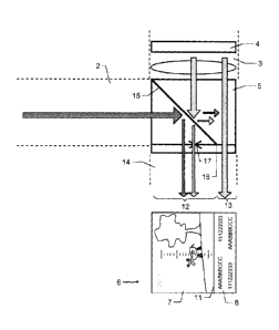
Figure 4a shows a first embodiment according to the
invention for producing the combined overall image
comprising day vision display region and exclusive display
region.
For this purpose, the observation device has a day vision
channel 2 and an information channel 3 with a single energy-
saving graphic display 4 - with downstream display optical
system - for producing a display image.
For combining the day vision channel 2 and the information
channel 3, a combination optical system 5 is provided
between day vision channel 2 and information channel 3.
According to the invention, the combination optical system 5
has a first zone for superposing at least a part of the day
vision image with a first part of the display image and a
second zone for exclusive provision of a second part of the
display image. As a result, the division, according to the
invention, of the combined overall image into the day vision
display region (or superposition region) - produced by the
14
CA 02670169 2009-06-22
first zone - and the exclusive display region separated from
this region - and produced by the second zone of the
combination optical system - is achieved.
As shown in Figure 4a, the combination optical system 5 can
be formed for this purpose as a beam splitter prism with a
beam splitter surface 16 which extends over the total beam
cross-section of the day vision and information channel and
is divided into two different part-regions.
A first part-region of the beam splitter surface 16 - which
forms the first zone of the combination optical system 5 -
has a partly transparent coating 15, so that radiation
incident in this region - both from the day vision channel 2
and from the information channel 3 - is guided in each case
partly and optionally with superposition into the indication
channel 14.
A second part-region of the beam splitter surface 16 - which
forms the second zone of the combination optical system -
is, for example, not coated, so that radiation incident form
the information channel 3 is guided - in particular
undeflected and completely - into the indication channel 14.
Radiation incident on this part-region from the day vision
channel 2 is transmitted, likewise undeflected and in
particular completely, so that it is not guided into the
indication channel 14 or caused to bypass the indication
channel 14. In addition, the day vision channel radiation
caused to bypass the indication channel 14 by the second
zone can, for example, be absorbed by an absorber material
so that said radiation is not reflected or scattered by
radiation guide walls. As a result, reflected or scattered
components of the day vision channel radiation caused to
bypass the indication channel 14 according to the invention
can be prevented from entering the indication channel to
cause interference. According to a further embodiment, a
brightness sensor can additionally be arranged after the
CA 02670169 2009-06-22
combination optical system in such a way that the brightness
of the day vision channel radiation caused to bypass the
indication channel by the second zone can be measured.
In an alternative manner of combination of information
channel and day vision channel 3, 2 to give the indication
channel 14, the second zone of the combination optical
system can also be formed so as to be totally reflective
instead of transmittive, so that once again radiation
incident there from the information channel 2 is guided
completely into the indication channel 14 and radiation
incident there from the day vision channel 2 is not guided
into the indication channel 14.
As is known according to the prior art, a reticule plate 17
can be arranged downstream of the beam splitter prism, by
means of which reticule plate a line pattern is produced in
the combined overall image and thus information regarding
azimuthal and/or elevation angle can be provided.
Figure 4b shows a plan view of the beam splitter surface 16
provided in the beam splitter prism from Figure 4a. The
first region 12 which is shown as a dotted line and - as
already described - forms the first zone of the beam
splitter prism 16 has the partly transparent coating 15 - in
particular with specified transmission and reflection ratio
- whereas the lower region 13 of the beam splitter surface
is formed to be transmittive and, for example, is not
coated. For example, the partly transparent coating 15 can
be applied by vapor deposition only to the upper part 12 of
the surface 16.
Figure 5 shows the combination optical system 5 from Figure
4a, here the reticule plate not being arranged after the
combination optical system 5 but a line pattern 17 being
integrated directly into the beam splitter prism - for
example by means of laser engraving.
16
CA 02670169 2009-06-22
According to a further development of the invention, the
laser engraving forming the line pattern 17 is provided in a
plane which is parallel to and is close as possible to the
boundary line between the coated and the uncoated region, in
particular the plane of the line pattern comprising the
boundary line - which separates the first zone of the
combination optical system from the second zone.
Since the plane of the line pattern is focused by the eye of
a user, in the case of the described arrangement of the line
pattern close to the boundary line the focusing plane is
also present close to this boundary line between first and
second zone, with the result that a sharp image of the
boundary line or a sharply displayed separation between day
vision display region and pure display region is produced in
the combined overall image. This permits a clear and
distinct display of the overall image and simplified
recognition of the information displayable in the display
region for a user.
In a day vision mode, i.e. during the day and with the day
vision channel opened, a day vision image can now be
provided in the day vision display region. If required,
superposition information can additionally be displayed by
means of the display - in the first part of the display
which is provided for superposition. In the exclusive
display region, on the other hand, only a display image
produced by the second part of the display - in particular
test information - is displayed.
In a night vision mode, i.e. during the night and/or with
the day vision channel closed, the indication provided for
the user is produced completely by the display, different
indication options being available. For example, a map or
an infrared image can be shown by the first part of the
display and text information can be provided by the second
part, which is shown in the exclusive display region.
17
CA 02670169 2009-06-22
Alternatively, the cohesive display image can also be
produced over the total indication region of the observation
device by the display, for which - as a result of the
coating present in part - an intensity adaptation of the
part-images produced by the first and second part of the
display can however advantageously be effected. The
cohesive display image produced in this manner - by means of
which, for example, a thermal image or a stored photo is
displayed - can of course in turn have electronically
superposed text information.
Figure 6 shows an alternative embodiment of the combination
optical system 5, which is now formed by a special beam
splitter prism. The beam splitter prism is formed in such a
way and arranged in such a way between day vision channel
and information channel 2, 3 that the first zone 12 - having
a beam splitter surface with partly transparent coating 15 -
extends over the total cross-section of the day vision
channel 2 but only over a part of the cross-section of the
information channel 3. On the other hand, the second zone
13 has no splitter surface and, in a wavelength range
relevant for the information channel radiation, is formed so
as to be completely transmittive and extends over the
remaining part of the information channel cross-section.
Once again, the division, according to the invention, of the
combined overall image 6, produced by the combination
optical 5, into day vision display region 7 (or
superposition region) and pure display region 8 can be
produced thereby.
By means of an arrangement of the reticule plate 17 directly
downstream of the prism, it is once again possible to
achieve the effect according to the invention, already
described with reference to Figure 5, whereby the boundary
edge 18 between first and second zone 12, 13 is arranged in
the same focusing plane as the reticule plate 17, with the
18
CA 02670169 2009-06-22
result that sharp imaging of the boundary 11 or separation
of the two image regions 7, 8 according to the invention in
the overall image 6 is once again realized.
Figure 7 shows a further embodiment according to the
invention of the combination optical system 5 with upstream
reticule plate 17 having, for example, an etched line
pattern, the combination optical system having an opaque
region 20 in the plane of the reticule plate for producing
the pure display region, so that exclusively a part of the
display image is shown in the display region of the combined
overall image and no superposition with day vision image
takes place.
For example, the reticule plate 17 or the beam splitter
prism representing the combination optical system 5 can for
this purpose have a coating 20 which is opaque to light and
provides the second zone. Since in this embodiment of the
combination optical system 5, too, the reticule plate 17 is
once again arranged in a plane which contains the boundary
line between first and second zone of the combination
optical system 5, an exclusive display region sharply
separated from the day vision display region is once again
provided in the combined overall image.
Figure 8 shows a further alternative embodiment comprising,
as combination optical system 15, a beam splitter surface
having two differently coated part-regions. A first part-
region has a partly transparent or partly reflective coating
15. The day vision display region in the overall image is
produced by this region of the combination optical system.
The second part-region on the other hand has a coating 21
which, for example, is reflective, so that display image
information beams are guided completely into the indication
channel and the pure display region is thus produced in the
overall image. Beams incident from the day vision channel
on this region having a reflective coating are on the other
19
CA 02670169 2009-06-22
hand deflected away so that, according to the invention,
exclusively a part of the image of the display 4 is shown in
the pure display region of the overall image and a
superposition with a generally relatively bright day vision
image is prevented. As a result, clear and distinct
recognizability of the information to be provided can be
ensured in the pure display region of the overall image.
Figure 9 shows a further embodiment with displaceable
combination optical system 5.
The combination optical system 5 is arranged so as to be
displaceable between day vision channel and information
channel in such a way that in a first position of the
combination optical system 5 - represented by a dashed line
- exclusively a display image is provided in the total
indication region (i.e. in both part-regions of the combined
overall image 6). Electronically, the cohesive display
image produced by the display can nevertheless be divided
into two parts (for example into a night vision image region
and an information region). In a second position of the
combination optical system 5, on the other hand, exclusively
the day vision image is shown in the day vision display
region of the combined overall image 6 and exclusively a
part of the display image is shown in the pure display
region.
As a result, a division, according to the invention, of the
overall image 6 is now possible, in which either the day
vision image or a first part of the display image -
alternatively selectable - is provided in the day vision
display region 7. In the exclusive display region 8, a
second part of the display image produced by the display 4
is always shown.
For example, the combination optical system 5 is formed for
this purpose as a totally reflective element 19, in
CA 02670169 2009-06-22
particular as a mirror, the reflective element 19 covering
the total cross-section of day vision and information
channel in the first position - shown as a dashed line - and
covering only a proportion of the cross-section of the day
vision channel and of the information channel in the second
position.
In addition, an opaque coating 20 can be provided in the
plane 22 of the reticule plate, the coating 20 covering a
slightly higher proportion of the channel cross-section than
the reflective element 19 in its second position. This
means that this opaque coating 20 extends at least over the
reflective element 19 in its second position, with the
result that once again a sharp boundary 11 forms in the
overall image 6 between the day vision image and the display
image when the plane 22 of the reticule plate is focused -
for example by the eye of a user.
Of course, these figures shown represent schematically only
possible working examples. The various approaches can,
according to the invention, be combined with one another and
with methods or functions of observation devices of the
generic type of the prior art - such as, for example, night
vision function, laser rangefinder, electronic compass, etc.
In the figures shown, the representation of further
generically present components - such as, for example,
further beam-shaping or beam-deflecting optical systems in
day vision, display and indication channel - is
substantially dispensed with for reasons of clearer
representation and for better understanding.
21