Note: Descriptions are shown in the official language in which they were submitted.
CA 02670361 2015-02-11
, 77675-76PPH
TITLE
Methods and Apparatus of Downhole Fluids Analysis
CROSS REFERENCE TO RELATED APPLICATIONS
[0001] This application is related to co-pending and commonly owned
United States
Patent Application Numbers 11/203,932, filed August 15, 2005, entitled
"Methods and
Apparatus of Downhole Fluid Analysis" and 11/858,138, filed September 20,
2007, entitled
"Circulation Pump for Circulating Downhole Fluids, and Characterization
Apparatus of
Downhole Fluids".
FIELD
[0002] The present invention relates to the field of sampling and
analysis of downhole
fluids of a geological formation for evaluating and testing the formation for
purposes of
exploration and development of hydrocarbon-producing wells, such as oil or gas
wells. More
particularly, the present disclosure is directed to methods and apparatus
utilizing a downhole
fluid sampling and analysis apparatus that is configured or designed for
capturing formation
fluids in a portion of a flowline utilizing, in part, a single valve
apparatus, and characterizing the
fluids downhole.
BACKGROUND
10003] Downhole fluid sampling and analysis is an important and
efficient investigative
technique typically used to ascertain characteristics and nature of geological
formations having
hydrocarbon deposits. In this, typical oilfield exploration and development
includes downhole
fluid sampling and analysis for determining petrophysical, mineralogical, and
fluid properties of
1
CA 02670361 2009-06-29
26.0427
hydrocarbon reservoirs. Fluid characterization is integral to an accurate
evaluation of the
economic viability of a hydrocarbon reservoir formation.
100041 Typically, a complex mixture of fluids, such as oil, gas, and
water, is found
downhole in reservoir formations. The downhole fluids, which are also referred
to as formation
fluids, have characteristics, including pressure, temperature, volume, among
other fluid
properties, that determine phase behavior of the various constituent elements
of the fluids. In
order to evaluate underground formations surrounding a borehole, it is often
desirable to obtain
samples of formation fluids in the borehole for purposes of characterizing the
fluids, including
composition analysis, fluid properties and phase behavior. Wireline formation
testing tools are
disclosed, for example, in U.S. Patent Nos. 3,780,575 and 3,859,851, and the
Reservoir
Formation Tester (RFT) and Modular Formation Dynamics Tester (MDT) of
Schlumberger are
examples of sampling tools for extracting samples of formation fluids from a
borehole for
surface analysis.
[0005] Formation fluids under downhole conditions of composition, pressure
and
temperature typically are different from the fluids at surface conditions. For
example,
downhole temperatures in a well could range from 300 degrees F. When samples
of downhole
fluids are transported to the surface, change in temperature of the fluids
tends to occur, with
attendant changes in volume and pressure. The changes in the fluids as a
result of
transportation to the surface cause phase separation between gaseous and
liquid phases in the
samples, and changes in compositional characteristics of the formation fluids.
[0006] Techniques also are known to maintain pressure and temperature of
samples
extracted from a well so as to obtain samples at the surface that are
representative of downhole
formation fluids. In conventional systems, samples taken downhole are stored
in a special
chamber of the formation tester tool, and the samples are transported to the
surface for laboratory
2
CA 02670361 2009-06-29
26.0427
analysis. During sample transfer from below surface to a surface laboratory,
samples often are
conveyed from one sample bottle or container to another bottle or container,
such as a
transportation tank. In this, samples may be damaged during the transfer from
one vessel to
another.
[0007] Furthermore, sample pressure and temperature frequently change
during
conveyance of the samples from a wellsite to a remote laboratory despite the
techniques used for
maintaining the samples at downhole conditions. The sample transfer and
transportation
procedures currently in use are known to damage or spoil formation fluid
samples by bubble
formation, solid precipitation in the sample, among other difficulties
associated with the
handling of formation fluids for surface analysis of downhole fluid
characteristics.
[0008] In addition, laboratory analysis at a remote site is time
consuming. Delivery of
sample analysis data takes anywhere from a couple of weeks to months for a
comprehensive
sample analysis. This hinders the ability to satisfy users' demand for real-
time results and
answers (i.e., answer products). Typically, the time frame for answer products
relating to
surface analysis of formation fluids is a few months after a sample has been
sent to a remote
laboratory.
[0009] As a consequence of the shortcomings in surface analysis of
formation fluids,
recent developments in downhole fluid sampling and analysis include techniques
for isolating
and characterizing formation fluids downhole in a wellbore or borehole. In
this, the MDT may
include one or more fluid analysis modules, such as the Composition Fluid
Analyzer (CFA) and
Live Fluid Analyzer (LFA) of Schlumberger, for example, to analyze downhole
fluids sampled
by the tool while the fluids are still located downhole.
[0010] In downhole fluid sampling and analysis modules of the type
described above,
formation fluids that are to be sampled and analyzed downhole flow past a
sensor module
3
CA 02670361 2015-02-11
77675-76PP11
associated with the fluid sampling and analysis module, such as a spectrometer
module, which
analyzes the flowing fluids by infrared absorption spectroscopy, for example.
In this, an
Optical Fluid Analyzer (OFA), which may be located in the fluid analysis
module, may
identify fluids in the flow stream and quantify the oil and water content.
U.S. Patent
No. 4,994,671 describes a borehole apparatus having a testing chamber, a light
source, a
spectral detector, a database, and a processor. Fluids drawn from the
formation into the
testing chamber are analyzed by directing the light at the fluids, detecting
the spectrum of the
transmitted and/or backscattered light, and processing the information (based
on information
in the database relating to different spectra), in order to characterize the
formation fluids.
[0011] In addition, U.S. Patents Nos. 5,167,149 and 5,201,220 describe
apparatus for
estimating the quantity of gas present in a fluid stream. A prism is attached
to a window in
the fluid stream and light is directed through the prism to the window. Light
reflected from
the window/fluid flow interface at certain specific angles is detected and
analyzed to indicate
the presence of gas in the fluid flow.
[0012] As set forth in U.S. Patent No. 5,266,800 monitoring optical
absorption
spectrum of fluid samples obtained over time may allow one to determine when
formation
fluids, rather than mud filtrates, are flowing into the fluid analysis module.
Further, as
described in U.S. Patent No. 5,331,156, by making optical density (OD)
measurements of the
fluid stream at certain predetermined energies, oil and water fractions of a
two-phase fluid
stream may be quantified.
[0013] Conventionally, multiple valves are utilized in downhole fluid
sampling and
analysis modules of the type described above to control flow of formation
fluids through the
4
CA 02670361 2009-06-29
26.0427
flowlines of the fluid analysis modules. For example, co-pending and commonly
owned United
States Patent Application Number 11/203,932, filed August 15, 2005, entitled
"Methods and
Apparatus of Downhole Fluid Analysis", discloses the use of a plurality of
valves for isolating
formation fluids in a part of the flowline of a downhole sampling and analysis
module. Fig. 7
schematically represents one example of a fluid sampling and analysis module
with a flowline
and multiple valve configuration for downhole characterization of fluids by
isolating or
capturing the formation fluids. In systems of the type depicted in Fig. 7,
motors are provided
downhole to actuate the valves, and a driver board is configured to control
operation of the
valves and associated motors. Typically, seal valves are employed for purposes
of opening or
closing the flowlines. The seal valves also may be used for directing fluids
through the fluid
sampling and analysis module.
[0014] The fluid control systems of the type described above have multiple
components
and operating parts, and require space in the downhole modules. In
consequence, there is a
need for a simple, yet reliable, fluid control system that provides the
functionality described
above, yet requires minimal space and downhole hardware for its operations.
SUMMARY
[0015] In consequence of the background discussed above, and other factors
that are
known in the field of downhole fluid sampling and analysis, applicants
discovered methods and
apparatus for downhole characterization of formation fluids by isolating the
fluids from the
formation and/or borehole in a flowline of a fluid sampling and analysis
module. In some
embodiments of the present disclosure, the fluids are isolated with a single
valve flow control
system that is integrated with the primary flowline and characteristics of the
isolated fluids are
determined utilizing, in part, a pressure and volume control unit (PVCU).
CA 02670361 2009-06-29
26.0427
[0016] The applicants further discovered that when the isolated fluid
sample is circulated
in a closed loop line, accuracy of phase behavior measurements can be
improved. Therefore, in
order to circulate the sample in a closed loop line, a circulation pump is
provided in the flowline
of the apparatus.
[0017] According to one aspect of the present disclosure, there is
provided a downhole
fluid characterization apparatus configured for operation downhole, within a
borehole. The
apparatus includes a fluid sampling and analysis module having a primary
flowline with a first
end for formation fluids to enter and a second end for the fluids to exit the
fluid sampling and
analysis module. A bypass flowline in fluid communication with the primary
flowline is
provided, and a fluid control system interconnecting the primary flowline and
the bypass
flowline. The fluid control system has a first position interconnecting a
first port of the primary
flowline with a second port of the primary flowline for formation fluids to
flow in the primary
flowline, and a second position interconnecting the first port of the primary
flowline with a first
port of the bypass flowline and the second port of the primary flowline with a
second port of the
bypass flowline for formation fluids to flow, via the bypass flowline, in the
primary flowline,
wherein fluid flow in the primary flowline is maintained during operation of
the fluid control
system between the first position and the second position. In aspects of the
present disclosure,
in the first position of the fluid control system, the bypass flowline
comprises a circulation
flowline for captured formation fluids to circulate in a closed loop of the
circulation flowline.
[0018] In other aspects herein, the fluid sampling and analysis module
includes a
circulation pump for circulating captured formation fluids in the closed loop
of the circulation
flowline. In other embodiments, the fluid sampling and analysis module
includes at least one
first sensor structured and arranged for measuring parameters of interest
downhole, within a
borehole, wherein the parameters of interest relate to captured formation
fluids in the circulation
flowline, and the at least one first sensor comprising one or more of a
density/viscosity sensor; a
6
p
CA 02670361 2009-06-29
26.0427
pressure sensor; and an imager. In yet other aspects herein, the fluid
sampling and analysis
module includes a pump unit in fluid communication with the bypass flowline
for varying
pressure and volume of captured fluids.
[0019] Aspects of the present disclosure include a pressure compensation
unit associated
with the fluid control system, the pressure compensation unit being structured
and arranged for
balancing pressure at opposite ends of the fluid control system to borehole
pressure. The fluid
sampling and analysis module may further comprise a plurality of sensors
structured and
arranged for measuring parameters of interest relating to fluids withdrawn
from the formation.
The fluid control system may comprise a shaft structured and arranged for
longitudinal
movement in a housing; the shaft having a through hole extending
longitudinally and three
orifices; an annular space between the shaft and the housing, and four seals
attached to the shaft
in the annular space between the shaft and the housing, wherein the shaft and
the inner wall of
the housing being shaped so that in combination with the three orifices,
through hole and annular
space between the shaft and the housing fluid flow in the primary flowline is
not blocked during
operation of the fluid control system between the first position and the
second position.
[00201 In certain embodiments, a tool configured to be located downhole
for sampling
and characterizing formation fluids located downhole in an oilfield reservoir
includes a fluid
analysis module, the fluid analysis module having a flowline for fluids
withdrawn from a
formation to flow through the fluid analysis module, the flowline having a
first end for the fluids
to enter and a second end for the fluids to exit the fluid analysis module;
the flowline comprising
a primary flowline and a bypass flowline; and the fluid analysis module
further comprising a
single valve interconnecting the primary flowline and the bypass flowline, the
single valve being
operable to a first position for formation fluids to flow in the primary
flowline, and to a second
position for formation fluids to flow, via the bypass flowline, in the primary
flowline, wherein
7
CA 02670361 2009-06-29
26.0427
the bypass flowline comprises a closed loop flowline for captured fluids when
the valve is in the
first position.
[0021] In yet other embodiments, fluid flow in the primary flowline is
maintained during
operation of the valve between the first and the second positions. The fluid
analysis module
may further comprise a pressure compensation unit structured and arranged for
balancing
pressure at opposite ends of the valve so that operation of the valve between
the first and the
second positions is at a balanced borehole pressure.
[0022] Aspects herein provide a fluid flow control system structured to
control flow of
downhole fluids through a fluid sampling and analysis module configured for
operation
downhole, within a borehole, the fluid sampling and analysis module comprising
a primary
flowline and a bypass flowline, in fluid communication with the primary
flowline, for downhole
fluids withdrawn from a formation to flow through the fluid sampling and
analysis module, the
primary flowline having a first end for the fluids to enter and a second end
for the fluids to exit
the fluid sampling and analysis module. The fluid flow control system
comprises a movable
shaft configured and designed for operation downhole, within a borehole, the
movable shaft
being operable to selectively interconnect the primary flowline and the bypass
flowline of the
fluid sampling and analysis module, wherein the movable shaft has a first
operating position
interconnecting a first port of the primary flowline with a second port of the
primary flowline,
and a second operating position interconnecting the first port of the primary
flowline with a first
port of the bypass flowline and the second port of the primary flowline with a
second port of the
bypass flowline, wherein in the first position of the movable shaft downhole
fluids flow in the
primary flowline, and in the second position of the moveable shaft downhole
fluids flow, via the
bypass flowline, in the primary flowline; and fluid flow in the primary
flowline is maintained
during operation of the movable shaft between the first and the second
operating positions.
8
CA 02670361 2009-06-29
26.0427
[0023] In aspects herein, the fluid flow control system may include a
housing; the
movable shaft being structured and arranged in the housing for movement
thereof in a
longitudinal direction, wherein the movable shaft has a central through hole
through which the
downhole fluids flow in a longitudinal direction thereof; an annular space
between an outer
surface of the movable shaft and an inner surface of the housing; and three
orifices for directing
flow of downhole fluids in the primary flowline and the bypass flowline,
wherein the shaft and
the inner wall of the housing being shaped so that in combination with the
three orifices, through
hole and annular space between the shaft and the housing fluid flow in the
primary flowline is
not blocked during movement of the fluid control system between the first and
the second
operating positions. A pressure compensation unit is structured and arranged
for balancing
pressure at opposite ends of the movable shaft so that operation of the
moveable shaft between
the first and the second operating positions is at a balanced borehole fluid
pressure.
[0024] Certain embodiments herein provide a method of downhole
characterization of
formation fluids utilizing a downhole tool comprising a fluid sampling and
analysis module
having a primary flowline, a bypass flowline and a single valve configured and
designed for
selectively interconnecting the primary flowline and the bypass flowline for
flowing formation
fluids through the fluid sampling and analysis module and for capturing
formation fluids in a
closed loop of the bypass flowline, the method comprising setting the valve in
a first operating
position so that formation fluids flow through the primary flowline;
monitoring at least a first
parameter of interest relating to formation fluids flowing in the primary
flowline; when a
predetermined criterion for the first parameter of interest is satisfied,
setting the valve in a
second operating position so that formation fluids flow, via the bypass
flowline, in the primary
flowline; capturing formation fluids in the closed loop of the bypass flowline
by returning the
valve to the first operating position; balancing pressure at opposite ends of
the valve so that
operation of the valve between the first and the second operating positions is
at a balanced fluid
9
CA 02670361 2015-05-12
675-76PPH
pressure; and characterizing captured formation fluids by operation of one or
more sensor
structured and arranged on the bypass flowline. =
[0025] In certain embodiments, a method includes characterizing
captured formation
fluids includes determining one or more fluid property of the captured fluids.
In other aspects
the method includes determining one or more fluid property comprises changing
fluid
pressure of the captured formation fluids by varying volume of the captured
fluids before
determining one or more fluid property. One or more fluid property may be
determined after
changing fluid pressure.
[0025a] In other embodiments, there is provided a downhole apparatus,
comprising: a
primary flowline for conveying the fluids therein, the primary flowline
comprising a first end
for allowing the fluids to enter and a second end for allowing the fluids to
exit; a bypass
flowline in fluid communication with the primary flowline, the bypass flowline
comprising a
first port for allowing the fluids to enter and a second port for allowing the
fluids to exit, and
the first and second ports of the bypass flowline being separated; a fluid
control system
interconnecting the primary flowline and the bypass flowline, the fluid
control system having
a single valve assembly with a first position interconnecting the first end of
the primary
flowline with the second end of the primary flowline, such that the fluids
flow directly in the
primary flowline, and a second position interconnecting the first end of the
primary flowline
with the first port of the bypass flowline, and interconnecting the second end
of the primary
flowline with the second port of the bypass flowline, such that the fluids
flow, via the bypass
flowline, in the primary flowline; wherein the first position of the fluid
control system forms a
circulation flowline to capture and to circulate the fluids in a closed loop;
and a circulation
pump for circulating the fluids in the closed loop of the circulation
flowline.
[0025b] In other embodiments, there is provided a downhole apparatus
for
characterizing fluids withdrawn from a formation, comprising: a primary
flowline for
conveying the fluids therein, the primary flowline comprising a first end for
allowing the
fluids to enter and a second end for allowing the fluids to exit; a bypass
flowline in fluid
communication with the primary flowline, the bypass flowline comprising a
first port for
CA 02670361 2015-05-12
675-76PPH
allowing the fluids to enter and a second port for allowing the fluids to
exit, and the first and
second ports of the bypass flowline being separated; a fluid control system
interconnecting the
primary flowline and the bypass flowline, the fluid control system having a
single valve
assembly with a first position interconnecting the first end of the primary
flowline with the
second end of the primary flowline, such that the fluids flow directly in the
primary flowline,
and a second position interconnecting the first end of the primary flowline
with the first port
of the bypass flowline, and interconnecting the second end of the primary
flowline with the
second port of the bypass flowline, such that the fluids flow, via the bypass
flowline, in the
primary flowline; and at least one first sensor structured and arranged for
measuring
parameters of interest downhole, wherein the first position of the fluid
control system forms a
circulation flowline to capture and to circulate the fluids in a closed loop,
wherein the
parameters of interest relate to the fluids in the circulation flowline, and
wherein the at least
one first sensor comprising one or more of a density/viscosity sensbr, a
pressure sensor, and
an imager.
[0025c] In other embodiments, there is provided a downhole apparatus,
comprising: a
primary flowline for conveying the fluids therein, the primary flowline
comprising a first end
for allowing the fluids to enter and a second end for allowing the fluids to
exit; a bypass
flowline in fluid communication with the primary flowline, the bypass flowline
comprising a
first port for allowing the fluids to enter and a second port for allowing the
fluids to exit, and
the first and second ports of the bypass flowline being separated; a fluid
control system
interconnecting the primary flowline and the bypass flowline, the fluid
control system having
a single valve assembly with a first position interconnecting the first end of
the primary
flowline with the second end of the primary flowline, such that the fluids
flow directly in the
primary flowline, and a second position interconnecting the first end of the
primary flowline
with the first port of the bypass flowline, and interconnecting the second end
of the primary
flowline with the second port of the bypass flowline, such that the fluids
flow, via the bypass
flowline, in the primary flowline; and a pressure compensation unit associated
with the fluid
control system, the pressure compensation unit being structured and arranged
for balancing
pressure at opposite ends of the fluid control system to borehole pressure.
= 10a
CA 02670361 2015-05-12
675-76PPH
[0025d] In other embodiments, there is provided a downhole apparatus
for
characterizing fluids withdrawn from a formation, comprising: a primary
flowline for
conveying the fluids therein, the primary flowline comprising a first end for
allowing the
fluids to enter and a second end for allowing the fluids to exit; a bypass
flowline in fluid
communication with the primary flowline, the bypass flowline comprising a
first port for
allowing the fluids to enter and a second port for allowing the fluids to
exit, and the first and
second ports of the bypass flowline being separated; a fluid control system
interconnecting the
primary flowline and the bypass flowline, the fluid control system having a
single valve
assembly with a first position interconnecting the first end of the primary
flowline with the
second end of the primary flowline, such that the fluids flow directly in the
primary flowline,
and a second position interconnecting the first end of the primary flowline
with the first port
of the bypass flowline, and interconnecting the second end of the primary
flowline with the
second port of the bypass flowline, such that the fluids flow, via the bypass
flowline, in the
primary flowline; and a plurality of sensors structured and arranged for
measuring parameters
of interest relating to fluids withdrawn from the formation.
[0025e] In other embodiments, there is provided a downhole apparatus,
comprising: a
primary flowline for conveying the fluids therein, the primary flowline
comprising a first end
for allowing the fluids to enter and a second end for allowing the fluids to
exit; a bypass
flowline in fluid communication with the primary flowline, the bypass flowline
comprising a
first port for allowing the fluids to enter and a second port for allowing the
fluids to exit, and
the first and second ports of the bypass flowline being separated; and a fluid
control system
interconnecting the primary flowline and the bypass flowline, the fluid
control system having
a single valve assembly with a first position interconnecting the first end of
the primary
flowline with the second end of the primary flowline, such that the fluids
flow directly in the
primary flowline, and a second position interconnecting the first end of the
primary flowline
with the first port of the bypass flowline, and interconnecting the second end
of the primary
flowline with the second port of the bypass flowline, such that the fluids
flow, via the bypass
flowline, in the primary flowline, wherein the fluid control system comprises:
a shaft
structured and arranged for longitudinal movement in a housing; the shaft
having a through
hole extending longitudinally and three orifices; an annular space between the
shaft and the
10b
=
CA 02670361 2015-05-12
375-76PPH
housing, and four seals attached to the shaft in the annular space between the
shaft and the
housing, wherein the shaft and the inner wall of the housing being shaped so
that in
combination with the three orifices, through hole and annular space between
the shaft and the
housing fluid flow in the primary flowline is not blocked during operation of
the fluid control
system between the first position and the second position.
[002511 In other embodiments, there is provided a downhole tool,
comprising: a
flowline for conveying the fluids therein, the flowline having a first end for
allowing the
fluids to enter and a second end for allowing the fluids to exit, the flowline
comprising a
primary flowline and a bypass flowline; a single valve interconnecting the
primary flowline
and the bypass flowline, the single valve being operable to a first position
for the fluids to
flow directly in the primary flowline, and to a second position for formation
fluids to flow, via
the bypass flowline, in the primary flowline, wherein: the bypass flowline
comprises a closed
loop flowline for capturing the fluids when the single valve is in the first
position; and a
pressure compensation unit structured and arranged for balancing pressure at
opposite ends of
the valve so that operation of the single valve between the first and the
second positions is at a
balanced borehole pressure.
[.00250 In other embodiments, there is provided a method of downhole
characterization
of formation fluids utilizing a downhole tool comprising a primary flowline, a
bypass
flowline, and a single valve for selectively interconnecting the primary
flowline and the
bypass flowline for control of flowing formation fluids and for capturing the
formation fluids
in a closed loop of the bypass flowline, the method comprising: setting the
single valve in a
first operating position so that the formation fluids flow through the primary
flowline;
monitoring at least a first parameter of interest relating to formation fluids
flowing in the
primary flowline; when a predetermined criterion for the first parameter of
interest is satisfied,
setting the single valve in a second operating position so that formation
fluids flow, via the
bypass flowline, in the primary flowline; capturing the formation fluids in
the closed loop of
the bypass flowline by returning the single valve to the first operating
position; balancing
pressure at opposite ends of the single valve so that operation of the single
valve between the
first and the second operating positions is at a balanced fluid pressure; and
characterizing the
10c
CA 02670361 2015-05-12
675-76PPH
captured formation fluids by operation of one or more sensors structured and
arranged on the
bypass flowline.
[0026] Additional advantages and novel features of the present
disclosure will be set
forth in the description which follows or may be learned by those skilled in
the art through
reading the materials herein or practicing the invention. The advantages of
the invention may
be achieved through the means recited in the attached claims.
BRIEF DESCRIPTION OF THE DRAWINGS
[0027] The accompanying drawings illustrate some of the embodiments
disclosed
herein and are a part of the specification. Together with the following
description, the
drawings demonstrate and explain principles of the present disclosure.
[0028] Fig. 1 is a schematic representation in cross-section of an
exemplary operating
environment of the methods and apparatus of the present disclosure.
[0029] Fig. 2 is a schematic representation of one embodiment of a
system for
downhole sampling and analysis of formation fluids according to the present
disclosure with
an exemplary tool string deployed in a wellbore.
=
1 Od
=
õ
CA 02670361 2009-06-29
26.0427
[0030] Fig. 3 shows schematically one embodiment of a tool string
according to the
present disclosure with a fluid sampling and analysis module having a flowline
and fluid flow
control system for downhole sampling and analysis of formation fluids.
[0031] Fig. 4A schematically represents one fluid sampling and analysis
module with a
flowline and single valve apparatus configuration according to one embodiment
of the present
disclosure for downhole characterization of fluids by isolating or capturing
the formation fluids.
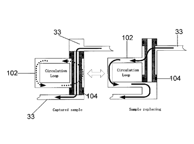
[0032] Fig. 4B is a schematic depiction of the operations of a flowline
and single valve
apparatus configuration according to the present disclosure.
[0033] Fig. 5A illustrates schematically one fluid sampling and analysis
module with a
flowline and single valve apparatus configuration and a pressure compensating
system according
to one embodiment of the present disclosure for downhole characterization of
fluids by isolating
or capturing the formation fluids.
[0034] Fig. 5B illustrates schematically another fluid sampling and
analysis module with
a flowline and single valve apparatus configuration and a pressure
compensating system
according to another embodiment of the present disclosure for downhole
characterization of
fluids by isolating or capturing the formation fluids.
[0035] Fig. 5C illustrates schematically one flowline and single valve
apparatus
configuration according to one embodiment of the present disclosure for a
downhole fluid
sampling and analysis module.
[0036] Fig. 5D illustrates schematically fluid pressure conditions for the
flowline and
single valve apparatus configuration of Fig. 5C according to one embodiment of
the present
disclosure.
11
CA 02670361 2009-06-29
. ,
26.0427
[0037] Fig. 6A is a schematic depiction of the operations of a
flowline and single valve
apparatus configuration and pressure compensating system according to one
embodiment of the
present disclosure.
[0038] Fig. 6B is a schematic depiction of the step-by-step
operations of a flowline and
single valve apparatus configuration and pressure compensating system
according to one
embodiment of Fig. 6A.
[0039] Fig. 7 schematically represents an example of a fluid
sampling and analysis
module with a flowline and multiple valve configuration for downhole
characterization of fluids
by isolating or capturing the formation fluids.
[0040] Throughout the drawings, identical reference numbers indicate
similar, but not
necessarily identical elements. While the present disclosure is susceptible to
various
modifications and alternative forms, specific embodiments have been shown by
way of example
in the drawings and will be described in detail herein. However, it should be
understood that
the invention is not intended to be limited to the particular forms disclosed.
Rather, the
invention is to cover all modifications, equivalents and alternatives falling
within the scope of
the invention as defined by the appended claims.
DETAILED DESCRIPTION
[0041] Illustrative embodiments and aspects of the present
disclosure are described
below. In the interest of clarity, not all features of an actual
implementation are described in
the specification. It will of course be appreciated that in the development of
any such actual
embodiment, numerous implementation-specific decisions must be made to achieve
the
developers' specific goals, such as compliance with system-related and
business-related
constraints, that will vary from one implementation to another. Moreover, it
will be appreciated
12
CA 02670361 2009-06-29
26.0427
that such development effort might be complex and time-consuming, but would
nevertheless be
a routine undertaking for those of ordinary skill in the art having benefit of
the disclosure herein.
[0042] The present disclosure is applicable to oilfield exploration and
development in
areas such as downhole fluid sampling and analysis using one or more fluid
sampling and
analysis modules in Schlumberger's Modular Formation Dynamics Tester (MDT),
for example.
[0043] Fig. 1 is a schematic representation in cross-section of an
exemplary operating
environment of the present disclosure wherein a service vehicle 10 is situated
at a wellsite having
a borehole or wellbore 12 with a borehole tool 20 suspended therein at the end
of a wireline 22.
Fig. 1 depicts one possible setting, and other operating environments also are
contemplated by
the present disclosure. Typically, the borehole 12 contains a combination of
fluids such as
water, mud filtrate, formation fluids, etc. The borehole tool 20 and wireline
22 typically are
structured and arranged with respect to the service vehicle 10 as shown
schematically in Fig. 1,
in an exemplary arrangement.
[0044] Fig. 2 is an exemplary embodiment of a system 14 for downhole
analysis and
sampling of formation fluids according to the one possible embodiment of the
present disclosure,
for example, while the service vehicle 10 is situated at a wellsite (note Fig.
1). In Fig. 2, a
borehole system 14 includes a borehole tool 20, which may be used for testing
earth formations
and analyzing the composition of fluids from a formation. The borehole tool 20
typically is
suspended in the borehole 12 (note also Fig. 1) from the lower end of a
multiconductor logging
cable or wireline 22 spooled on a winch 16 (note again Fig. 1) at the
formation surface. The
logging cable 22 typically is electrically coupled to a surface electrical
control system 24 having
appropriate electronics and processing systems for the borehole tool 20.
[0045] Referring also to Fig. 3, the borehole tool 20 includes an
elongated body 26
encasing a variety of electronic components and modules, which are
schematically represented in
13
CA 02670361 2015-02-11
77675-76PPH
Figs. 2 and 3, for providing necessary and desirable functionality to the
borehole tool 20. A
selectively extendible fluid admitting assembly 28 and a selectively
extendible tool-anchoring
member 30 (note Fig. 2) are respectively arranged on opposite sides of the
elongated body 26.
Fluid admitting assembly 28 is operable for selectively sealing off or
isolating selected portions
of a borehole wall 12 such that pressure or fluid communication with adjacent
earth formation is
established. The fluid admitting assembly 28 may be a single probe module 29
(depicted in Fig.
3) and/or a packer module 31 (also schematically represented in Fig. 3).
Examples of borehole
tools are disclosed in the aforementioned U.S. Patents Nos. 3,780,575 and
3,859,851, and in U.S.
Patent No. 4,860,581.
[0046] One or more fluid sampling and analysis modules 32 are
provided in the tool
body 26. Fluids obtained from a formation and/or borehole flow through a
flowline 33, via the
fluid analysis module or modules 32, and then may be discharged through a port
of a pumpout
module 38 (note Fig. 3). Alternatively, formation fluids in the flowline 33
may be directed to
one or more fluid collecting chambers 34 and 36, such as 1, 2 3/4, or 6 gallon
sample chambers
and/or six 450 cc multi-sample modules, for receiving and retaining the fluids
obtained from the
formation for transportation to the surface. Examples of the fluid sampling
and analysis
modules 32 are disclosed in U.S. Patent Application Publications Nos.
2006/0243047A1 and
2006/0243033A1.
[0047] The fluid admitting assemblies, one or more fluid analysis
modules, the flow path
and the collecting chambers, and other operational elements of the borehole
tool 20, are
controlled by electrical control systems, such as the surface electrical
control system 24 (note Fig.
2). The electrical control system 24, and other control systems situated
in the tool body 26, for
example, may include processor capability for characterization of formation
fluids in the tool 20,
as described in more detail below.
14
CA 02670361 2009-06-29
26.0427
[0048] The system 14, in its various embodiments, may include a control
processor 40
operatively connected with the borehole tool 20. The control processor 40 is
depicted in Fig. 2
as an element of the electrical control system 24. Methods disclosed herein
may be embodied
in a computer program that runs in the processor 40 located, for example, in
the control system
24. In operation, the program is coupled to receive data, for example, from
the fluid sampling
and analysis module 32, via the wireline cable 22, and to transmit control
signals to operative
elements of the borehole tool 20.
[0049] The computer program may be stored on a computer usable storage
medium 42
associated with the processor 40, or may be stored on an external computer
usable storage
medium 44 and electronically coupled to processor 40 for use as needed. The
storage medium
44 may be any one or more of presently known storage media, such as a magnetic
disk fitting
into a disk drive, or an optically readable CD-ROM, or a readable device of
any other kind,
including a remote storage device coupled over a switched telecommunication
link, or future
storage media suitable for the purposes and objectives described herein.
[0050] In some embodiments of the present disclosure, the methods and
apparatus
disclosed herein may be embodied in one or more fluid sampling and analysis
modules of
Schlumberger's formation tester tool, the Modular Formation Dynamics Tester
(MDT). In this,
a formation tester tool, such as the MDT, may be provided with enhanced
functionality for the
downhole characterization of formation fluids and the collection of formation
fluid samples.
The formation tester tool may be used for sampling formation fluids in
conjunction with
downhole characterization of the formation fluids.
[0051] Fig. 4A schematically represents one fluid sampling and analysis
module with a
flowline and single valve apparatus configuration according to one embodiment
of the present
disclosure for downhole characterization of fluids by isolating or capturing
the formation fluids.
CA 02670361 2015-02-11
77675-76PPH
Fig. 48 is a schematic depiction of the operations of a flowline and single
valve apparatus
configuration according to one embodiment of Fig. 4A.
[0052] In Fig. 4A, a fluid sampling and analysis module 32 has a
flowline and single
valve apparatus 100 for downhole characterization of fluids by isolating or
capturing the
formation fluids (note also Fig. 3). In some embodiments, the flowline and
single valve
apparatus 100 of Fig. 4A may be integrated with the primary flowline 33 of the
module 32.
The flowline and single valve apparatus 100 includes a bypass flowline 102 in
fluid
communication, via main flowline 33, with a formation surrounding a borehole.
The flowline
and valve apparatus 100 may include a secondary flowline 115 for purposes of a
backup
flowline.
[0053] In the embodiment depicted in Fig. 4A, the flowline and single
valve apparatus
100 includes a single valve apparatus 104 that interconnects the primary
flowline 33 with the
bypass flowline 102. The single valve apparatus 104 is situated so as to
control the flow of
formation fluids in the bypass flowline segment 102 of the primary flowline 33
and to isolate
or capture formation fluids in the bypass flowline 102. The single valve
apparatus 104
operates as a 4-way 2-position valve. In this, in one position of the single
valve apparatus 104
(note Fig. 4A) a first port of the primary flowline 33 is connected with a
first port of the
bypass flowline 102 and a second port of the bypass flowline 102 is connected
with a second
port of the primary flowline 33 such that fluids flow in the primary flowline
33 via the bypass
flowline 102. Note Fig. 4A. In another position of the single valve apparatus
104 (note Fig.
4A) a first port of the primary flowline 33 is connected with a second port of
the primary
flowline 33 and a first port of the bypass flowline 102 is connected with a
second port of the
bypass flowline 102 such that fluids flow in the primary flowline 33 and
fluids are captured or
isolated in the bypass flowline 102.
[0054] A relief valve 106 may be situated on the primary flowline 33. For
example, if
high pressure fluid were to be captured in the bypass flowline 102 due to
failure of the valve
16
õ
CA 02670361 2009-06-29
26.0427
apparatus 104 the high pressure can be released through relief valve 106 to
prevent injury or
safety issues after the tool returns to the surface. A check valve 121 may be
provided for
releasing unexpected high pressure in the primary flowline 33, for example,
due to any blockage
or failure in the downhole fluid analysis module. However, the relief valve
106 and the check
valve 121 are not required for fluid flow control between the primary and
bypass flowlines.
[0055] A pressure/temperature gauge 108 may be provided on the bypass
flowline 102 to
acquire pressure and/or temperature measurements of fluids in the bypass
flowline 102. A
density and viscosity sensor (vibrating rod) 110 also may be provided to
measure characteristics
of formation fluids flowing through or captured in the bypass flowline 102.
[0056] A pump unit 111 may be arranged with respect to the bypass flowline
102 to
control volume and pressure of formation fluids retained in the bypass
flowline 102. A
scattering detector system 112 may be provided on the bypass flowline 102 to
detect particles,
such as asphaltene, bubbles, oil mist from gas condensate, that come out of
isolated fluids in the
bypass flowline 102. A circulation pump 114 is provided on the bypass flowline
102 for
circulating formation fluids that are isolated in the bypass flowline 102 in a
closed loop formed
by the bypass flowline 102 and the single valve apparatus 104.
[0057] The bypass flowline 102 is looped, via the single valve apparatus
104, and the
circulation pump 114 is provided on the looped flowline so that formation
fluids isolated in the
bypass flowline 102 may be circulated, for example, during phase behavior
characterization.
When the isolated fluid sample in the bypass flowline 102 is circulated in a
closed loop line,
accuracy of phase behavior measurements can be improved.
[0058] Referring to Fig. 4B, during the captured sample mode, formation
fluids flow
inside the primary flowline 33 with the single valve apparatus 104 in a first
operating position.
At this time, other fluid analysis modules analyze the characteristics of the
sample flowing inside
17
CA 02670361 2009-06-29
26.0427
the primary flowline 33. When the sample flow becomes stable, the sample
contamination is
sufficiently low, and sample is single phase, the formation fluids are flowed
through the bypass
flowline 102 by moving the single valve apparatus 104 from the first operating
position to a
second operating position. Then, the sample flows into the bypass flowline 102
for a few
minutes, for example, and the single valve apparatus 104 is moved to the first
operating position
so that sample fluid is captured or isolated in a closed loop of the bypass
flowline 102 and the
single valve apparatus 104.
[0059] The density and viscosity sensor 110 measures the sample density
and the
viscosity. The speed of the circulation pump 114 (sample flow rate) can be
controlled by the
surface positioned software based on the density and the viscosity measured by
the density and
viscosity sensor 110. Next, the circulation pump 114 is started (note Fig.
4A). Then the pump
unit 111 changes the pressure of the sample captured inside the bypass
flowline 102 while the
pressure/temperature gauge 108 measures the pressure change and the
temperature of the sample.
The scattering detector 112 monitors the solid (solid precipitation from
liquid or oil coming out
from condensate) or gas (bubble from liquid) coming out.
[0060] In certain aspects, the circulation pump 114 works as an agitator
to mix the
sample inside the bypass flowline 102 and to create bubbles or solids inside
the bypass flowline
102. With this function of the circulation pump 114, bubbles and solids that
are generated are
carried to the scattering detector 112. The pressure value is recorded when
the scattering
detector 112 detects the bubbles or solids.
[0061] Fig. 5A is a schematic depiction of one fluid sampling and analysis
module with a
flowline and single valve apparatus configuration and a pressure compensating
system according
to one embodiment of the present disclosure for downhole characterization of
fluids by isolating
or capturing the formation fluids. Fig. 5B is a schematic depiction of another
fluid sampling
18
CA 02670361 2015-02-11
77675-76PPH
and analysis module with a flowline and single valve apparatus configuration
and a pressure
compensating system according to another embodiment of the present disclosure.
In the
apparatus of Fig. 5B, a secondary flowline 115 is provided and additional
details are provided
with respect to the pump 111, the valve 104, and the circulation pump 114.
[0062] Fig. 5C illustrates schematically one flowline and single valve
apparatus
configuration according to one embodiment of the present disclosure for a
downhole fluid
sampling and analysis module. Fig. 5D illustrates schematically fluid pressure
conditions for
the flowline and single valve apparatus configuration of Fig. 5C according to
one embodiment
of the present disclosure.
[0063] In addition to the elements discussed above in connection with Fig.
4A, the
apparatus of Fig. 5A includes a pressure compensating system 130 having an oil
line 132 that
connects pressure compensation oil in a chamber 134 with a far end of the
single valve 104.
Note also Figs. 6A and 6B. As depicted in Fig. 5D, fluid pressure at ends of
the single valve
apparatus 104 is balanced by the pressure compensation oil 134. In this, as
depicted in Fig.
6B, borehole pressure is equalized with the pressure of the oil 134 of the
pressure
compensating system 130 so that there is no differential pressure across the
valve apparatus
104 to impede movement of the valve apparatus. Moreover, balancing pressure
inside the
flowline and single valve apparatus 100 with borehole pressure prevents
collapse of or
damage to housing 119 of the flowline and single valve apparatus 100.
[0064] The configurations depicted in Figs. 5A and 5B provide solutions to
the issues
identified above with respect to fluid flow control systems with multiple
valves. In this, the
single valve structure of the present disclosure eliminates the need for seal
valves and
simplifies the overall structure and configuration of the flowline of a
sampling and analysis
module. In particular, in contrast with a seal valve that is actuated by a DC
motor wherein
each seal valve of a fluid sampling and analysis module requires an associated
motor for
operation, the single valve
19
CA 02670361 2015-02-11
77675-76PPH
structure of the present disclosure eliminates multiple valve and motor
arrangements. By
replacing seal valves with a single valve of the present disclosure, it is
possible to reduce the
electrical components and circuitry in the downhole sampling and analysis
apparatus.
[0065] As depicted in Figs. 5A and 5B, the apparatus includes a
closed loop
circulation flowline 102. In this, according to the configurations of Figs. 5A
and 5B, the dead
volume of the closed loop flowline is minimized to reduce the stroke of the
pump 111 for
depressurization. Furthermore, length of the sampling and analysis module 32
is reduced. In
contrast with the structure depicted in Fig. 7, the configurations of the
flowlines of Figs. 5A
and 5B reduce the dead volume. For example, a seal valve has a dead volume of
12 cc,
whereas the single valve structure of the present disclosure has a dead volume
of 1.6 cc. In
consequence, the single valve structure minimizes fluid dead volume in the
flowline and valve
of the sampling and analysis module.
[0066] The single valve structures of Figs. 5A and 5B provide
replacement of a
sample that is captured in the bypass flowline through a one way flow of
fluids. Therefore,
the structure of the single valve minimizes residual formation fluids in the
closed loop
circulation flowline. The single valve has a through hole extending
longitudinally through the
center of a piston shaft. Sampled formation fluids flow through the through
hole during
sample capture in the bypass flowline 102. In this, the single valve structure
eliminates the
need for additional flowline hardware for formation fluids to flow through the
primary
flowline during sample capture in the bypass flowline.
[0067] In the embodiment depicted in Fig. 5A, the flowline and single
valve apparatus
100 includes a housing 119 and a single valve apparatus 104 that interconnects
the primary
flowline 33 with the bypass flowline 102. The single valve apparatus 104 is
situated so as to
control the flow of formation fluids in the bypass flowline segment 102 of the
primary
flowline 33 and to isolate or capture
CA 02670361 2009-06-29
. .
26.0427
formation fluids in the bypass flowline 102. The single valve apparatus 104
operates as a
4-way 2-position valve. The single valve apparatus 104 includes a valve
actuator 118 and a
valve shaft 107 (note also Fig. 5C) having, for example, four pressure seal
points 109 located on
the valve shaft 107. The seal points 109 may be dynamic seals that are
disposed on the valve
shaft 107 and move with the shaft in valve housing 117. The valve shaft 107
has a center
through hole and three side holes or orifices 113. The holes are in fluid
connection with each
other and with an annular space between the valve shaft 107 and the inner wall
of the valve
housing 117. Note also Fig. 5C.
[0068] In one position of the single valve apparatus 104 (note Fig.
5A) a first port of the
primary flowline 33 is connected with a second port of the primary flowline 33
and a first port of
the bypass flowline 102 is connected with a second port of the bypass flowline
102 such that
fluids flow in the primary flowline 33 and fluids are captured or isolated in
the bypass flowline
102. Note Fig. 5A. In another position of the single valve apparatus 104 a
first port of the
primary flowline 33 is connected with a first port of the bypass flowline 102
and a second port of
the primary flowline 33 is connected with a second port of the bypass flowline
102 (note Fig.
5C) such that such that fluids flow in the primary flowline 33 via the bypass
flowline 102. As
evident from Fig. 5C, the inner wall of the valve housing 117 is contoured or
shaped so that, in
combination with the seal points 109 and orifices 113 fluid flow is maintained
in the primary
flowline 33 and the bypass flowline 102 during movement or operation of the
single valve
apparatus between the two above mentioned positions.
[0069] A pressure/temperature gauge 108 may be provided on the
bypass flowline 102 to
acquire pressure and/or temperature measurements of fluids in the bypass
flowline 102. A
density and viscosity sensor (vibrating rod) 110 also may be provided to
measure characteristics
of formation fluids flowing through or captured in the bypass flowline 102.
21
CA 02670361 2009-06-29
26.0427
[0070] A pump unit 111 may be arranged with respect to the bypass flowline
102 to
control volume and pressure of formation fluids retained in the bypass
flowline 102. The pump
unit 111 has a piston actuator 124 that drives pump piston 126. A scattering
detector system
112 may be provided on the bypass flowline 102 to detect particles, such as
asphaltene, bubbles,
oil mist from gas condensate, that come out of isolated fluids in the bypass
flowline 102. A
circulation pump 114 is provided on the bypass flowline 102 for circulating
formation fluids that
are isolated in the bypass flowline 102 in a closed loop formed by the bypass
flowline 102 and
the single valve apparatus 104. An imager 116, such as charge couple device or
a CMOS, may
be provided on the bypass flowline 102 to image fluid flowing in the bypass
flowline 102.
[0071] The bypass flowline 102 is looped, via the single valve apparatus
104, and the
circulation pump 114 is provided on the looped flowline so that formation
fluids isolated in the
bypass flowline 102 may be circulated, for example, during phase behavior
characterization.
When the isolated fluid sample in the bypass flowline 102 is circulated in a
closed loop line,
accuracy of phase behavior measurements can be improved.
[0072] Fig. 5B is a schematic depiction of another fluid sampling and
analysis module
with a flowline and single valve apparatus configuration and a pressure
compensating system
according to another embodiment of the present disclosure. In the apparatus of
Fig. 5B, a
secondary flowline 115 is provided and additional details are provided with
respect to the pump
111, the valve 104, and the circulation pump 114. For example, the pump unit
111 may have a
piston actuator 124 that drives pump piston 126. The actuator unit 124 may
include an encoder
125 for monitoring rotations of, for example, a stepper motor 127 that is
connected with, for
example, a ball screw and nut assembly 129, which converts rotary motion of
the motor 127 to
longitudinal motion of the pump piston 126. In one embodiment of the present
disclosure, the
valve actuator 118 may comprise a brushless DC motor 131 that is connected
with a ball screw
and nut assembly 133 for controlling movement and position of the single valve
apparatus 104.
22
CA 02670361 2015-02-11
77675-76PPH
Position switches 140 may be provided to monitor positions of the pump shaft
126 and the valve
shaft 107. In combination the aforementioned elements of the pump actuator
unit 124 and the
valve actuator 118 may be utilized for controlling movement and position of
the piston 126 of
the pump unit 111 and the valve shaft 107 of the single valve apparatus 104.
[0073] In some embodiments, the circulation pump 114 may include a
brushless DC
motor 135 and a magnet coupler and impeller 137, as described in detail in
aforementioned
United States Patent Application Number 11/858,138.
[0074] Although the exemplary embodiments depicted in Figs. 5A and 5B
show two
actuators for the pump unit 111 and the single valve apparatus 104, the
present disclosure
contemplates an actuating system having a single actuator for both the pump
unit 111 and the
valve apparatus 104. In this, an actuating system having a single motor, for
example, a
brushless DC motor, with a suitable clutch connector assembly connected with
the motor would
provide drive and control functions for both pump unit 111 and the valve
apparatus 104. For
example, a suitable clutch mechanism maintains position of the valve shaft 107
while sample
fluids are replaced in the bypass flowline (note Fig. 6B, Step 1). Then, the
single motor
releases the clutch so that the valve shaft 107 changes its position to the
sample capturing
position (note Fig. 6B, Step 2). Next, the clutch holds the position until the
next sample
replacing sequence. While the valve shaft 107 is moved from the sample
replacing position to
the sample capturing position, another mechanism causes the pump shaft 126 to
move backward
so that space for pressurization is created in the pump unit ll 1. After
sample capture, the
mechanism moves the pump shaft 126 forward to pressurize the captured fluids
in the bypass
flowline, and then moves the pump shaft backward to depressurize the captured
fluids (note Fig.
6B, Step 3). By use of a suitable clutch system it is possible to decouple the
piston of the pump
111 and the valve shaft 107 while using a single motor. Moreover, movement of
the pump
23
CA 02670361 2009-06-29
= =
26.0427
piston 126 may be varied to a pressurize/depressurize configuration instead of
a single
depressurization movement. In this, it is possible to draw fluids into the
bypass flowline, move
the pump piston 126 in a forward direction to pressurize the captured fluids
in the bypass
flowline, and then move the pump piston 126 in a backward direction to
depressurize the
captured fluids in the bypass flowline. An actuating system with a single
motor and a clutch
system would utilize less space and require less power than a two actuator
system depicted in
Figs. 5A and 5B. However, the present disclosure contemplates use of both
types of actuating
systems.
[0075] Fig. 6A is a schematic depiction of the operations of a
flowline and single valve
apparatus configuration and pressure compensating system according to one
embodiment of the
present disclosure. As previously discussed above in connection with Fig. 4B,
during the
captured sample mode, formation fluids flow inside the primary flowline 33
with the single valve
apparatus 104 in a first operating position. At this time, other fluid
analysis modules analyze
the characteristics of the sample flowing inside the primary flowline 33. When
the sample flow
becomes stable, the sample contamination is sufficiently low, and sample is
single phase, the
formation fluids are flowed through the bypass flowline 102 by moving the
single valve
apparatus 104 from the first operating position to a second operating
position. Then, the sample
flows into the bypass flowline 102 for a few minutes, for example, and the
single valve apparatus
104 is moved to the first operating position so that sample fluid is captured
or isolated in a closed
loop of the bypass flowline 102 and the single valve apparatus 104.
[0076] Fig. 6B is a schematic step-by-step depiction of the
operations of a flowline and
single valve apparatus configuration and pressure compensating system
according to the present
disclosure. Referring also to Fig. 5A, the single valve 104 has a longitudinal
valve shaft 107
that is movable in valve housing 117. Four pressure seal points 109, for
example, dynamic
seals are located on the valve shaft 107 and move with the shaft. The valve
shaft 107 has a
24
CA 02670361 2009-06-29
=
26.0427
center through hole and three side holes or orifices 113. The holes are in
fluid connection with
each other. As evident from Fig. 5C, the inner wall of the valve housing 117
is contoured so
that fluid flow in the primary flowline 33 and the bypass flowline 102 is not
interrupted during
movement of the valve shaft 107 from sample captured to sample replacing and
vice versa. An
actuator 118 is connected with the valve shaft 107 so as to move the valve
shaft 107 in the
housing 117 of the valve such that the position of the valve shaft 107
relative to the valve
housing 117 is changed.
[0077] Referring to Fig. 6B, for replacing the fluid in the
bypass flowline, formation
fluids flowing in the primary flowline are diverted to the bypass flowline.
The formation fluids
enter the loop of the bypass flowline and then return to the primary flowline.
In this, a closed
loop circulation flowline is provided by the interconnection of the single
valve and the bypass
flowline. Since the formation fluids reenter the primary flowline at the other
end of the bypass
flowline, sampled or captured fluids in the bypass flowline are replaced with
fresh formation
fluids.
[0078] The single valve system disclosed herein provides a
closed loop circulation
flowline for formation fluids that are isolated from the fluids in the primary
flowline to undergo
pressure changes in the circulation flowline. In this, the single valve 104
provides circulation
of captured fluids in the bypass flowline 102 without interrupting fluid flow
in the primary
flowline 33. A pressure balancing oil 134 (note Fig. 6A) is provided on both
sides of the single
valve piston shaft. The oil is in fluid communication with a pressure
compensator system 130
to balance the pressure in the valve. Therefore, if pressure in the primary
flowline fluctuates, or
the pressure in the circulation flowline changes, the valve piston shaft can
maintain its position
relative to the housing of the single valve. An actuating force of 20 kgf is
required for actuating
the piston shaft of the single valve, which is sufficient to overcome the
friction of the dynamic
seals of the single valve.
CA 02670361 2015-02-11
77675-76PPH
[00791 Fig. 7 schematically represents an example of a fluid sampling
and analysis
module 32 with a flowline and multiple valve apparatus 70 for downhole
characterization of
fluids by isolating or capturing the formation fluids. Detailed description of
the apparatus of
Fig. 7 may be found in co-pending and coinmonly owned United States Patent
Application
Number 11/203,932, filed August 15, 2005, entitled "Methods and Apparatus of
Downhole Fluid
Analysis", which discloses the use of a plurality of valves for isolating
formation fluids in a part
of the flowline of a downhole sampling and analysis module.
[0080] The apparatus 70 includes a bypass flowline 35 and a circulation
flowline 37 in
fluid communication, via main flowline 33, with a formation surrounding a
borehole. In Fig. 7,
the apparatus 70 includes two seal valves 53 and 55 operatively associated
with the bypass
flowline 35. The valves 53 and 55 are situated so as to control the flow of
formation fluids in
the bypass flowline segment 35 of the main flowline 33 and to isolate
formation fluids in the
bypass flowline 35 between the two valves 53 and 55. A valve 59 may be
situated on the main
flowline 33 to control fluid flow in the main flowline 33. For example, each
of the seal valves
53 and 55 may have an electrically operated DC brushless motor or stepping
motor with an
associated piston arrangement for opening and closing the valve.
[0081] One or more optical sensors, such as a 36-channels optical
spectrometer 56,
connected by an optical fiber bundle 57 with an optical cell or refractometer
60, and/or a
fluorescence/refraction detector 58, may be arranged on the bypass flowline
35, to be situated
between the valves 53 and 55. The optical sensors may be used to characterize
fluids flowing
through or retained in the bypass flowline 35. U.S. Patents Nos. 5,331,156 and
6,476,384, and
U.S. Patent Application Publication No. 2004/0000636A1
disclose methods of characterizing formation fluids.
26
CA 02670361 2015-02-11
77675-76PPH
[0082] A pressure/temperature gauge 64 and/or a resistance sensor 74
also may be
provided on the bypass flowline 35 to acquire fluid electrical resistance,
pressure and/or
temperature measurements of fluids in the bypass flowline 35 between seal
valves 53 and 55.
A chemical sensor 69 may be provided to measure characteristics of the fluids,
such as CO2,
H2S, pH, among other chemical properties. An ultra sonic transducer 66 and/or
a density and
viscosity sensor (vibrating rod) 68 also may be provided to measure
characteristics of
formation fluids flowing through or captured in the bypass flowline 35 between
the valves 53
and 55. U.S. Patent No. 4,860,581, discloses apparatus for fluid analysis by
downhole fluid
pressure and/or electrical resistance measurements. U.S. Patent No. 6,758,090
and Patent
Application Publication No. 2002/0194906A1 disclose methods and apparatus of
detecting
bubble point pressure and MEMS based fluid sensors, respectively.
[0083] A pump unit 71, such as a syringe-pump unit, may be arranged
with respect to
the bypass flowline 35 to control volume and pressure of formation fluids
retained in the
bypass flowline 35 between the valves 53 and 55. A detailed description of the
pump unit 71
is provided in the aforementioned United States Patent Application Number
11/203,932.
[0084] An imager 72, such as a CCD camera, may be provided on the
bypass flowline
35 for spectral imaging to characterize phase behavior of downhole fluids
isolated therein, as
disclosed in co-pending U.S. Patent Application No. 11/204,134, titled
"Spectral Imaging for
Downhole Fluid Characterization," filed on August 15, 2005.
[0085] A scattering detector system 76 may be provided on the bypass
flowline 35 to
detect particles, such as asphaltene, bubbles, oil mist from gas condensate,
that come out of
isolated fluids in the bypass flowline 35. A circulation pump 78 is provided
on the circulation
27
CA 02670361 2015-02-11
77675-76PPH
flowline 37. A detailed description of the circulation pump 78 is provided in
the
aforementioned United States Patent Application Number 11/858,138.
[0086] Since the circulation flowline 37 is a loop flowline of the
bypass flowline 35, the
circulation pump 78 may be used to circulate forrnation fluids that are
isolated in the bypass
flowline 35 in a loop formed by the bypass flowline 35 and the circulation
flowline 37.
[0087] The preceding description has been presented only to illustrate
and describe the
invention and some examples of its implementation. It is not intended to be
exhaustive or to
limit the invention to any precise form disclosed. Many modifications and
variations are
possible in light of the above teaching. The aspects herein were chosen and
described in order
to best explain principles of the invention and its practical applications.
The preceding
description is intended to enable others skilled in the art to best utilize
the invention in various
embodiments and aspects and with various modifications as are suited to the
particular use
contemplated. It is intended that the scope of the invention be defined by the
following claims.
28