Note: Descriptions are shown in the official language in which they were submitted.
CA 02670393 2010-12-01
LOW OPERATING HEAD POLISHING SAND FILTER
FIELD OF THE INVENTION
This invention relates to a novel low operating head polishing sand filter.
BACKGROUND OF THE INVENTION
Traditional or conventional designs of sand filtration are satisfactory and
effective water
treatment solutions in many large scale applications. However, the demands for
their
precise operation to achieve required performance to meet increasingly
stringent water
treatment regulations often result in excessive capital and operational
financial burdens.
Water treatment facilities that are complex to operate, generate excessive
volumes of
waste water or use chemicals, which may be difficult to manage properly and
further
complicate waste water disposal, are not desirable. Complex water treatment
facilities
require more skilled plant operators, which may not be available or affordable
in many
circumstances.
U.S. Patent No. 6,123,858, granted 26 September 2000, David H. Manz, discloses
a
novel intermittent slow sand filter and a method of using the intermittent
filter. More
particularly, this invention pertains to a novel slow sand filter which
remains effective,
even when intermittently operated, and which can be periodically cleaned
without
disturbing the action of the intermittent filter. The slow sand filter
apparatus comprises a
container having an upper portion and a lower portion; a water inlet in the
upper portion
of the container, the water inlet being connected to a supply of water; a
filter material
filling at least the lower portion of the container, the filter material
having a top surface
below the water inlet; a schmutzdeuke layer on the top surface of the filter
material; a
water outlet in the lower portion of the container below the top surface of
the filter
material; and a water level maintenance device in the upper portion which
maintains
water in the upper portion of the container at a maintenance level above the
top surface of
the filter material, the maintenance level being a balance between (1) a water
maintenance level that is sufficiently deep that water falling from the water
inlet onto the
top of the water in the container does not significantly disturb the
schmutzdeuke layer;
and (2) a water maintenance level that is sufficiently shallow that oxygen
from the air
above the water level can diffuse through the water and reach the schmutzdeuke
layer so
that the schmutzdeuke layer is maintained in living condition even when there
is no flow
of water through the water inlet.
A Biosand Water Filter (BSF) is described in detail in a paper entitled "New
Horizons for
Slow Sand Filtration", Dr. David Manz, P. Eng., published in the Proceedings
of the
Eleventh Canadian National Conference and Second Policy Forum on Drinking
Water
and the Biennial Conference of the Federal-Provincial-Territorial Committee on
Drinking
Water, Promoting Public Health Through Safe Drinking Water, April 3-6, 2004,
Calgary,
Alberta, pp. 682-692. The BSF is a patented water filtration technology that
grew out of
CA 02670393 2010-12-01
-2-
extensive evaluation and experience with traditional slow sand, rapid sand and
pressure
sand filters. The BSF is an effective, compact, simple and low cost variation
of slow sand filtration that is particularly useful in circumstances where
quality treatment
solutions need to be provided at minimal cost and the inconvenience of simple
manual
operation and cleaning are appropriate. For this reason more than 300,000
BSF's,
ranging in capacity from 20 litres per hour to 120,000 litres per hour are
used in more
than 70 countries.
The foregoing examples of the related art and limitations related thereto are
intended to
be illustrative and not exclusive. Other limitations of the related art will
become
apparent to those of skill in the art upon a reading of the specification and
a study of the
drawings.
SUMMARY OF THE INVENTION
The following embodiments and aspects thereof are described and illustrated in
conjunction with systems, tools and methods which are meant to be exemplary
and
illustrative, not limiting in scope. In various embodiments, one or more of
the
above-described problems have been reduced or eliminated, while other
embodiments are
directed to other improvements.
The invention is directed to a low operating head polishing sand filter
comprising:
(a) a five-layer media bed comprising small, medium and large crushed
quartzite; (b) an
untreated water inlet system; (c) an underdrain system; (d) a filtered water
collection and
outlet system; and (e) a backwash water inlet, collection and siphon outlet
system.
In addition to the exemplary aspects and embodiments described above, further
aspects
and embodiments will become apparent by reference to the drawings and by study
of the
following detailed descriptions.
DRAWINGS
Exemplary embodiments are illustrated in referenced figures of the drawings.
It is
intended that the embodiments and figures disclosed herein are to be
considered
illustrative rather than restrictive.
Figure 1 illustrates a top view of the low operating head polishing sand
filter with system
elements and water flow.
Figure 2 illustrates a cross-section of filter A'-A of Figure 1.
Figure 3 illustrates an elevation of a raw water inlet system.
CA 02670393 2009-05-22
WO 2008/080214 PCT/CA2007/000985
-3-
Figure 4 illustrates an elevation of a filtered water collection and outlet
system
(standpipe).
Figure 5 illustrates an elevation of a backwash water inlet system.
Figure 6 illustrates an elevation of a backwash water collection and siphon
outlet
system.
DETAILED DESCRIPTION OF THE INVENTION
Throughout the following description specific details are set forth in order
to provide a
more thorough understanding to persons skilled in the art. However, well known
elements may not have been shown or described in detail to avoid unnecessarily
obscuring the disclosure. Accordingly, the description and drawings are to be
regarded
in an illustrative, rather than a restrictive, sense.
It is necessary to review the important characteristics of commonly used sand
filtration
technologies in order to appreciate the significant advantages of the Low
Operating
Head Polishing Sand Filter (LHPF), as disclosed and claimed in this
application.
Rapid Sand and Pressure Sand Filters
Both rapid sand and pressure sand water filters (often called multi-media
filters when
the media in the filter bed is made up of more than one type of material or
two or more
of materials such as quartzite, anthracite or garnet sand) are commonly used
as
polishing filters in water treatment plants. Rapid sand filters have been used
for over
one hundred years. Rapid and pressure sand filters are typically used as part
of
conventional municipal water treatment systems in which pre-treatment is
provided by
adding coagulants to the water, thereby allowing the formation of coagulant
flocs which
capture the very small particles (including parasite cysts and oocysts) and
some
dissolved organic and inorganic compounds. The water containing the flocs is
then
sent to clarifiers or settling basins where they settle out of the water. The
'clarified
water' is then sent to rapid sand (which are relatively simple to control) or
to pressure
sand filters (which are more complex to control) for final polishing prior to
disinfection.
It is not common or practical to use either rapid sand or pressure sand
filters for
removing small amounts of oxidized iron or manganese as the flocs containing
these
metals are often too small to be efficiently captured. Other types of filter
media, with
an affinity for adsorbing iron and manganese, such as a natural zeolite known
as
CA 02670393 2009-05-22
WO 2008/080214 PCT/CA2007/000985
-4-
greensand, are commonly used. These media do need to be chemically regenerated
and
significant amounts of chemically charged waste water are produced in the
process.
Rapid sand filters are gravity operated sand filters; that is, the surface of
the untreated
water is not pressurized to provide the force necessary to cause the water to
move
through the filter. The required filtering force is provided by a depth of
water over the
filter media during operation, often one meter or more. During operation, a
rapid sand
filter resembles a swimming pool. Rapid sand filters normally have deep multi-
layer
and multi-material media beds, most of which interface with a very extensive
and often
massive underdrain system that also serves as the entry and distribution for
very large
volumes of treated water used in the backwash process. Rapid sand filters tend
to be
very large in structure.
Pressure sand filters are wholly contained in a closed vessel specially
designed to
withstand the forces resulting from operation under pressure. Pressure sand
filters are
very compact when compared to rapid sand filters. Similar to a rapid sand
filter, a
pressure filter contains several layers of media of different sizes and
material. Pressure
filters normally use a very compact underdrain/backwash system. When they are
not
filled with media, pressure sand filters are relatively light in weight and
are easily
transported. The media is added once the filters are deployed and the
necessary piping
is attached. Large capacity pressure filters may be several meters in
diameter.
Both pressure and rapid sand filters force the water through the filter.
Particulate
material is captured in narrow ranges of the filter bed, depending on its
design, until
there are no longer any locations within the media for particulate entrapment.
At this
time, the water, which still contains the offending particulate material, is
forced
completely through the filter and the filter exhibits what is known as
'breakthrough'
phenomena. Breakthrough is detected by an increase in turbidity of the
filtered water
(treated water is continuously monitored using in-line turbidity meters and
alarms).
Before breakthrough occurs or is observed to be starting, the rapid and
pressure sand
filters are cleaned using a very violent backwash process. Air and water
scours and
often mechanical rakes can be used to assist the cleaning process. The water
backwash
process is continued until the produced waste water becomes clear. The filter
is then
put back into production and is operated with production water sent to waste
until the
produced water exhibits a sufficiently low turbidity. At that time, the
produced water
is sent to treated water storage. The volume of waste water produced by rapid
sand
and pressure sand filters during the backwash process is large. During a
backwash the
media in the filter bed stratifies into layers with the finest and lightest
material
CA 02670393 2009-05-22
WO 2008/080214 PCT/CA2007/000985
-5-
concentrating on the top. If the backwash process, or the pre-treatment used
prior to
filtration, is not carefully performed the filter media can be damaged
(formation of mud
balls, short circuiting, flushing of fines, etc.). If coagulants and other
floc
development or capture enhancement chemicals are used, the waste water
generated
during cleaning can present a disposal problem.
Minimum characteristics of media beds for both rapid sand and pressure sand
filters are
specified by the American Water Works Association. Nonetheless, there remains
considerable opportunity for custom designs. The final design of most
significant rapid
sand filter systems, and less frequently, pressure filter systems are
evaluated and
confirmed using a pilot plant representative of the final design and operating
environment.
Traditional Slow Sand Filters and BioSand Water Filters
Traditional slow sand filters (SSF) and more recently the BioSand Water Filter
(BSF)
(an important variation of the slow sand filter) are known for their ability
to remove
very small inorganic and organic, living and dead particulate materials from
water.
Inorganic substances include all variety of suspended material including sand,
silt,
flocculated colloidal materials and oxidized iron and manganese and any
substances
adsorbed by them (including arsenic). Organic substances include pathogens in
the
form of parasites, bacteria and viruses. The filter is operated in such a
manner that the
filter develops a biolayer or schmutzdecke at the surface of the media bed.
The
removal characteristics of the schmutzdecke have been known for more than one
hundred and fifty years. The performance standard of the slow sand filter and
the BSF
is directly attributed to their low surface loading rate, approximately one-
tenth or less
of that for rapid sand and pressure filters, in combination with the low
operating heads
and fine grained material in the surface bed. Consequently, slow sand filters
have
surface areas ten or more times larger than that of rapid sand filters with
similar
surface loading. BSF's may have surface areas five to ten times as large as
rapid sand
filters with similar loading. The principal limitation of slow sand filtration
has been
the difficulty in cleaning the filter bed once the pores at its surface are
plugged to the
point that the flow through the filter is diminished to unacceptable rates.
The BSF
overcomes the cleaning limitations of traditional slow sand filters by
replacing the
procedure for removing the plugged surface layer with the ability to clean
this layer in
place, in other words, by re-suspending the material captured in the media
surface
using a gentle reverse flow and surface agitation and decanting the water
above the
media surface, which now contains the captured material, to waste. Because
traditional slow sand filters are so difficult to clean their use is not
recommended for
CA 02670393 2009-05-22
WO 2008/080214 PCT/CA2007/000985
-6-
filtering water with turbidity greater than 20 NTU or water containing
oxidized iron
and manganese. The BSF over comes these limitations by providing a simple,
easy to
perform cleaning system. However, the cleaning system used by the BSF becomes
more complex and expensive to install, as the filters approach the scale
typically used
in small to large municipal applications.
The media bed in typical slow sand filters is usually composed of material
with an
effective size, d10, of 0.35mm or less with a uniformity coefficient of 3.0 or
less. It is
generally believed that the lower the d10 and the uniformity coefficient, the
better the
filter media will perform. It is also required that the filter media meet
American Water
Works Associate (AWWA) standards for hardness and purity, AWWA - B -100, a
requirement typically achieved by using crushed and washed quartzite or
similar
materials. It is important that the filter media not have particles made of
soft shale or
mud stones that are high in oxidized metals. The AWWA specifies a minimum
depth
of filter bed, not including the underdrain materials, of approximately 0.6
meters,
though there is no literature or research data supporting the use of a deeper
'minimum'
bed. Traditional slow sand filters have used beds of more than 1.0 meter to
allow
several 'cleanings'. Each cleaning removes up to 5 cm before a 're-bedding' or
'topping-up' of the filter bed is required. The depth of 0.6 in has
historically been
attributed to the minimum depth required for virus deactivation, though this
has never
been conclusively determined. When the water is disinfected after filtration,
100%
virus or bacteria kills or deactivation are routinely achieved, as they are
when
conventional water treatment using coagulation, clarification, and rapid sand
or
pressure sand filtration are used. Chorine additions to treated water (or
water that does
not require treatment) are required throughout North America to the extent
that
minimum residual chlorine concentrations are detected at all points-of-use
throughout
the community being served. It is important to note that all pathogens that
are not
easily killed or deactivated by chlorination, such as the cysts and oocysts of
Giardia
and Cryptosporidia, must be removed. This task is readily performed by slow
sand
filtration technology and with some difficulty by treatment systems using
rapid sand or
pressure sand filtration technology. Slow sand filtration does not exhibit
'break
through' of inadequately treated raw water. Also, rapid and pressure sand
filters are
required to 'produce to waste', which is the practice of operating the
filters, after
cleaning, in such a way that the produced water is sent to disposal or waste
until they
capture sufficient material to enhance their filtration capabilities that they
produce
water of a quality that can be confidently assumed to contain the oocysts or
cysts or
pathogenic organisms. Slow sand filters demonstrate their ability to remove
inorganic
suspended particles from the moment they are placed back into operation,
though
CA 02670393 2009-05-22
WO 2008/080214 PCT/CA2007/000985
-7-
traditional slow sand filters may require several days to re-establish their
ability to
remove bacteria and viruses. Because the BSF media is cleaned-in-place it
never loses
its ability to remove bacteria and viruses.
Low Operating Head Polishing Sand Filter (LHPF)
The Low Operating Head Polishing Sand Filter (LHPF) according to the invention
is
an important improvement and grew out of a need to provide an effective,
physically
simple, operationally simple and robust, low-cost water treatment solution for
use in
small scale water treatment plants in circumstances where capital and
operational
resources are limited. The LHPF combines the water treatment capability of the
Biosand Water Filter (BSF) with the method and apparent convenience of
cleaning
associated with rapid and pressure sand filters. (Water polishing refers to
the ability of
a filter to remove very small particles from water.) The design of the LHPF
eliminates
the production of excessive volumes of waste water and need for extensive
pre-treatment and use of chemicals.
The design of the Low Operating Head Polishing Sand Filter (LHPF) exhibits the
same
particulate removal ability of slow sand filtration or the BSF but
incorporates a unique
clean-in-place system that has the same simplicity of design and operation as
that used
in pressure sand filters (without the need for the massive underdrain and
backwash
system characteristic of rapid sand filters), and the production of very low
volumes of
waste water similar to that associated with the BSF technology. As well, the
LHPF is
comparatively simple and inexpensive to design, construct, house and operate
when
compared to traditional slow sand filtration and rapid and pressure sand
filtration.
Figure 1 illustrates a top view of the low operating head polishing sand
filter with
system elements and water flow. The backwash water collection pipe, the
underdrain
system, the vertical outside wall of the filter, the diffuser basin, the
siphon outlet for
the backwash water, the pipes for the untreated water and backwash water to
waste, the
treated water supply to backwash water inlet supply system, the treated water
to storage
and the standpipe and backwash water inlet supply system are indicated by
boxes and
lead lines.
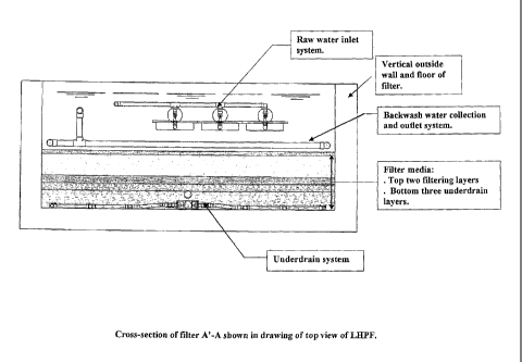
Figure 2 illustrates a cross-section of filter A' -A of Figure 1. The raw
water inlet
system, the vertical outside of the wall and floor of the filter, the backwash
water
collection and outlet system, the filter media comprised of the top two
filtering layers
and the bottom three underdrain layers, and the underdrain system are
indicated by
boxes and lead lines.
CA 02670393 2009-05-22
WO 2008/080214 PCT/CA2007/000985
-8-
Figure 3 illustrates an elevation of a raw water inlet system. The inlet pipe,
the
diffuser basin, the float valve, the raw water inlet control valve, the pipe
for the raw
water supply and the vertical outside wall and the floor of the filter are
indicated by
boxes and lead lines.
Figure 4 illustrates an elevation of a filtered water collection and outlet
system
(standpipe). The standpipe including the entire portion of the filtered water
outlet
system attached to the underdrain at the top of the tee connection, the
air/vacuum
release valve, the filtered water flow rate adjustment valve, the backwash
water
isolation valve, the filtered water control valve, the pipe for the filtered
water to the
storage, the tee connection to the backwash water inlet system, the pipe for
the
underdrain/filtered water collection system, and the vertical outside wall an
floor of the
filter are indicated by boxes and lead lines.
Figure 5 illustrates an elevation of a backwash water inlet system. The
vertical outside
wall and the floor of the filter, the pipe for the underdrain, the connection
to the
standpipe and the pipe for the treated water supply used for the backwash are
indicated
by boxes and lead lines.
Figure 6 illustrates an elevation of a backwash water collection and siphon
outlet
system. The siphon outlet, the wastewater flow control valve, the wastewater
operations valve, the pipe for the waster disposal and the vertical outside
wall and floor
of the filter are indicated by boxes and lead lines.
Design Features
The design of the LHPF incorporates all of the treatment and structural
benefits
associated with the BioSand Water Filter with the simplicity and convenience
of
cleaning associated with pressure sand filters.
The LHPF uses a unique filter bed which has filtration characteristics which
are the
same as or better than the BSF, but which eliminate the surface scraper used
by the
BSF to break up the surface of the media bed during cleaning. The LHPF also
incorporates an underdrain and backwash system similar to that used in
pressure filters.
The flow of filtered water in the LHPF is controlled using a 'weir-type'
outlet system
(outlet standpipe) connected directly to the filter underdrain system. This
concept is
similar to that used with traditional slow sand filters and the BSF. The use
of the
outlet standpipe ensures that the filter bed cannot be dewatered; an
occurrence that
CA 02670393 2009-05-22
WO 2008/080214 PCT/CA2007/000985
-9-
would allow air to enter the media bed and risk air binding that could only be
resolved
by initiating a backwash cycle. The maximum flow from the filter (often
specified by
regulatory authorities) is established during filter commissioning by the
provision and
adjustment of a filtered water flow rate adjustment valve, that is not used
during filter
operations. During normal operation the flow of water into the filter and the
maximum depth of water over the filter bed are established by mechanical float
valves
attached to the raw water inlet pipes within the filter itself. The flow of
water into the
filter cannot exceed its production. The combination of permissible maximum
head on
the filter bed and restricted flow rate eliminates the risk of compaction of
the top layer
of the media bed. The erosive power of the water from the raw water inlet
system is
eliminated by passing the water from the mechanical float controlled valves
into
perforated basins (called diffuser basins) located a short distance above the
minimum
depth of water in the filter. This ensures that the surface of the media
cannot be
disturbed (which is very important for slow sand filters). The rate of
filtered water
flow, the filter bed design and the hydraulic head loss across the filter bed
ensure that
the filter will meet water treatment expectations consistent with that of slow
sand filters
performing the same treatment function.
The outlet system is connected to the treated water supply used for filter
backwashing.
Once it is determined that filter production is unacceptably low, (perhaps
determined
by the examination of water glasses permitting observation of water depth in
the filter
and outlet head), filter production is isolated and backwash water is allowed
to enter
into the underdrain system. An air-vacuum control valve which is attached to
the top
of the outlet standpipe ensures that the filter produces treated water with
the outlet
under atmospheric pressure and backwashes under full backwash pump pressure.
In one embodiment, the media bed used in the LHPF can consist of at least five
layers
(depending on the scale of filter) of differently sized crushed quartzite
(silica) each
meeting the material characteristics required for slow, rapid or pressure sand
filters as
stated by the American Water Works Association (AWWA). The upper three layers
use uniform graded sizes (effective sizes of 0.15mm, 0.35mm and 1.0mm
respectively). The top layer provides most of the filtering action. The bottom
two
layers of the media bed (1/8 to 1/2 inch and 1/2 to 1 1/2 inch respectively)
allow
uniform vertical flow, downward and upward, through the filtering layers while
filtration is in progress and even distribution of the water across the entire
bottom of
the filter bed during a backwash. The use of crushed quartzite, rather than
rounded
particles of quartzite, reduces the magnitude of backwash flow rates required
to fluidize
CA 02670393 2009-05-22
WO 2008/080214 PCT/CA2007/000985
-10-
the top two layers. The maximum operating depth is selected such that the
maximum
hydraulic head produced across the filter bed does not result in filter bed
compaction.
Other sizes of media can work. The critical issues are that the top two layers
must
have an effective size less than 0.35 mm and the uniformity coefficient must
be 2.05 or
less. The top layer should have an effective size of 1/2 or less than the
second filtering
layer. The finest (top) underdrain layer must have an effective size at least
2 times that
of the filtering layer immediately above it and have a uniformity coefficient
of 2 or
less. Underdrain layers below the upper most underdrain layer must be
sufficiently
large to prevent intermixing of the layers. The key to the invention is to
size the top
two layers so that they are the only layers that fluidize. Because both layers
are
composed of particles of distinctly different sizes and with very low
uniformity
coefficients, they will settle into beds in exactly the same way after every
backwashing.
The backwash flow rate is controlled so that only these two layers fluidize.
The
fluidizing that occurs is much more vigorous than simple mechanical agitation.
The
volume of backwash is limited by the maximum depth of water in the filter when
cleaning. This volume is carefully calculated to conform with conventional
criteria
within the field of rapid sand filtration design.
The backwash of the LHPF is only intended to break up the surface layer (where
virtually all of the material is collected) and resuspend captured material.
This is
similar to a BSF, but unlike the LHPF, backwash process used by rapid sand
filters and
pressure sand filters, not only fluidizes the bed but also permits scouring
and flushing
of captured material from well within the filter bed itself. The backwash of a
rapid
sand or pressure sand filter must be long enough to ensure that all of the
captured
particles have been flushed from the interior of the media. Mechanical surface
agitation might be used if normal backwash is not considered sufficient.
As inferred above, the LHPF uses an underdrain system and backwash method that
closely resembles the method used in pressure sand filters but it is not
nearly as
extensive. The reason for this is that rapid sand filters must use relatively
large flow
rates of backwash water at low head to fluidize a deeper media bed composed of
larger
particles. In comparison, the LHPF must only fluidize the uppermost two layers
for a
short period of time to effectively remove and suspend captured particulate
material in
the backwash water. When the backwash flow is stopped, the top two fluidized
layers
in the LHPF collapse vertically into layers resembling the original filter
bed. This is
because each layer has a very different effective size and both layers are
comprised of
CA 02670393 2009-05-22
WO 2008/080214 PCT/CA2007/000985
-11-
uniformly graded particles. Remaining backwash water is 'squeezed' out and
upward
from the filter media and the cleaned media bed settles.
The design of the underdrain system used in a LHPF is fundamentally different
from
that used in a BSF system. In the BSF, a very gentle reverse flow (a kind of
low flow
rate backwash) is used that cannot fluidize the filter bed. Media beds used in
slow sand
filters are not intended to be fluidized. The reverse flow used in the BSF is
intended to
remove any gases that have been captured within the filter media and to
provide
sufficient water on the surface of the media to facilitate the suspension of
captured
particulate material (achieved by agitating the surface of the media layer).
The
suspension is then removed and the filter is ready for operation.
The wastewater produced during the backwash process is removed using
perforated
pipes located along and attached to the interior walls of the filter. The
holes in the pipe
face slightly downward to avoid capturing any of the fluidized media. They are
located
approximately ten centimetres or less above the surface of the media (all of
the water is
not removed). The perforations in the underdrain pipe system must be
sufficiently
small to prevent any of the particles in the bottommost underdrain layer from
entering
the system. The perforated pipes are attached to a siphon spillway system that
also acts
as an emergency overflow system. The rate of flow through this system is
controlled
by a dedicated waste water flow control valve which is not greater than the
capacity to
take the wastewater to disposal. A second, waste water operations valve is
used to
alternatively prevent flow from the filter until backwash is completed and is
then
opened to facilitate the siphon evacuation process. The same valve is left
open after
backwash is completed to provide emergency overflow protection. The wastewater
collection system and the siphon outlet system and method of control are
unique.
While siphon spillways per se are not novel, siphon spillways controlled and
operated
in the manner included in the design of the LHPF are novel.
It is advisable to divide the entire filtration plant into equal segments that
can be
cleaned independently and successfully using lower capacity distribution pumps
and
produce flow rates and volumes of wastewater that can be economically
evacuated and
disposed of.
Comparison of Sand Filters
All forms of slow sand filtration are very effective in removing very small
particles,
including parasites, bacteria and viruses, and oxidized iron and manganese
from water
without the use of pre-treatment associated with conventional water treatment.
CA 02670393 2009-05-22
WO 2008/080214 PCT/CA2007/000985
- 12-
Traditional slow sand filtration technology is not considered practical if the
untreated
water has a high turbidity or contains oxidized iron or manganese. The BSF
overcomes this limitation by incorporating a clean-in-place system that
eliminates the
need for filter scraping or surface media removal. However, the practicality
of the
mechanical system used by the BSF as part of its clean-in-place system is
limited to
lower capacity water treatment systems often well below the demands of even
small
communities. Traditional slow sand filtration does not produce any waste water
and
the BSF produces very little when compared to the volumes produced by rapid
and
pressure sand filters. BSF's do not lose their ability to treat water after
cleaning.
Traditional slow sand filters recover their ability to remove bacteria and
viruses after a
few days and rapid and pressure sand filters must produce to waste until the
water they
produce exhibits a sufficiently low turbidity (to guarantee parasite cyst and
oocyst
removal). Slow sand and BSF's are very simple to operate when compared to
rapid
and pressure sand filters. Slow sand filters are much larger (at least 10
times the
surface area for the same capacity) than rapid sand or pressure filters.
Traditional slow
sand filters are double the surface area of BSF's.
The following table compares the effectiveness, physical and operational
characteristics
and costs associated with traditional slow sand filters (TSSF), the BioSand
Water Filter
(BSF), rapid sand filters, pressure sand filters and the LHPF.
CA 02670393 2009-05-22
WO 2008/080214 PCT/CA2007/000985
-13-
eta w a~i
v1 w 4~ 44i C i U q 44; aa) aa) 3 ~" TA
C ^~ =~~r a u a c`ai a~ cl co 't~ id m a c
cd L." U L." U i a' U i N a~ bA of
>>> >C bC >o m a~ >na>o,u>ns~
a)
0'b
R3 = ) ^r~ i b C
(U 0
}, r" O O Q , aJ Q 71 0 y ord
+viG~a u Rtoc 13 'moo Go o 3~ ~~
y 0 0 > OU C t~ a~ O N a) 0 c a aj
U O + > > > ti ca as
2.14 U3
0
P,zz W
U U4. Z a, CZ Q) CZ O 0> o o Z. >c~i~w
ab
~y~ C O
CIS
~( O cd 1+ cd cqqd cd 'a a U
rA (U > ic3 O 0 G C YF >
cl,
UU u0 CIS 44- U Uo ~o U3 ~
^C
0 0
w "~ b v U 0.2 w O 4~ as c 0 ai
mw >
O O 0 n asJ } +a0i~ . yb
zz W ~t z z Cz a Z> as 2 E>W
Flj ca a c T.- a~i
> > > s.
~i~
p .?a~J ..+ G ai
44 4-i I~ill CIS
O a~ a) (L) a) U cd `~
0.2 p U.2 4) 0
>>> >C, >a >ni >(D Lt a) cu
aC>ik Z `l
co 0
O b y U v chi -zj U
cy C O E a~ CqE a) a)
O '~ w w 4-a N t, -fl 10
U eat a~a~a~ a~U >a a)a a) a)~
'n M 14 cd
411 cd
.. w z~ z Z Z >
U
r
a.) V)
42
C~ = = rn vi ..r ,,~~ cUd . N
(D alo as u +~'= a
w ~aCQ>v~UO o =~=> on
Wtea; x~ d
a O 4~ w Q OCA v1r%ra
CA 02670393 2009-05-22
WO 2008/080214 PCT/CA2007/000985
-14-
'C7~'
o a,a~a~o
> in
vi d 4-y
to)
cli
co E
0 ca U)
a) n 3 ~ v Od
C =
C13 cd
d ~=
U C
bl)
cq C C
030 0 ~~ ~o
cqj
pct `" oa
r r~ O A O U U N N O O ~F.yy ~i
Z^
NO
U U) ai
A U Ub C U 77a)
- cOd O d , O" q
~ ~ CJ3 ,fl !N U N a) ~ ti a)
3 3 3~ s~ a Cd c4
bq n o p
C
O C
.. U
' s7 3 ca V- L" C bn
^~o
p A... V > o A I N y v
.. o =. V b
L. i+ r .~ o a) 0 0
cll
wl b c~ +' d ee3 pa. a
av OI cd o" N ~'
bn C C~ iOõ O
W~ a~a x3a o~ za _ _ o w
CA 02670393 2009-05-22
WO 2008/080214 PCT/CA2007/000985
-15-
o
'~ p0 api p ~ U
O cd cd `d
NNj U (pNj
o S3 cd
'b cd
p0 ~ ~i "" cUd O
cd - O N
o-o in.. N v A,
P. Usti'
=b b
O Q
O U U
> n p > cd A
p ~ N ~.., N bn b_n
cd
O cad c Eg
cd
N C p cqj
3 3 3
O o o
a5~z p.~w > > >
o
cz
c's 'd
Q, 0
C
3 N ~ O
33
cls
v 3wo>
CA 02670393 2009-05-22
WO 2008/080214 PCT/CA2007/000985
- 16-
The following observations can be made:
1. The TSSF, BSF and LHPF's are all very effective in removing pathogens.
2. All types of slow sand filters are very effective at removing inorganic or
organic particulate material with or without pre-treatment. The TSSF is
limited, however, because a significant effort is required to clean it.
3. The TSSF, BSF and LHPF will not exhibit break through phenomena. Thus, it
is impossible for these filters to produce untreated water. Unlike rapid sand
and
pressure sand filters, TSSF, BSF and LHPF continue to improve their ability to
treat water until such time as the captured material completely stops the flow
of
water through them. The TSSF, BSF and LHPF are cleaned when their
capacity drops to unacceptably low levels (50 % of maximum production is
normal).
4. The TSSF, BSF and LHPF's are all very effective in removing oxidized iron
and manganese though the TSSF is not practical because of the significant
effort
required to clean it.
5. Except for having a relatively larger surface area, the LHPF and the BSF
are
structurally compact and simple to construct. Thus their construction costs
are
very low.
6. The TSSF, BSF, rapid sand filters (RSF) and LHPF are all appropriate for
use
in large scale applications.
7. The BSF, pressurized sand filter (PSF) and LHPF are particularly
appropriate
for use in small scale applications.
8. The TSSF produces almost no waste water. The BSF and the LHPF produce
only minor amounts of waste water. The RSF and the PSF produce very large
amounts of waste water.
9. The TSSF is simple to operate but it requires significant effort to clean.
10. The BSF and the LHPF are simple to operate and clean.
11. The RSF and PSF are complex to operate effectively but are relatively
simple to
clean.
12. The operator skill level required to successfully operate the TSSF, BSF
and
LHPF is relatively low. The skill level required to successfully operate RSF
and PSF is quite high.
13. The relative overall costs of operation and maintenance of the TSSF, BSF
and
LHPF is low to very low when compared to the costs of operation and
maintenance of the RSF and PSF.
While a number of exemplary aspects and embodiments have been discussed above,
those of skill in the art will recognize certain modifications, permutations,
additions
CA 02670393 2011-03-29
-17-
and sub-combinations thereof. It is therefore intended that the scope of the
claims should not be
limited by the preferred embodiments set forth in the description, but should
be given the
broadest interpretation consistent with the description as a whole.