Note: Descriptions are shown in the official language in which they were submitted.
CA 02670420 2009-05-22
WO 2007/067554 PCT/US2006/046427
ORTHODONTIC BRACKET AND
METHOD OF ATTACHING ORTHODONTIC BRACKETS TO TEETH
CROSS-REFERENCE TO RELATED APPLICATION
[0001] This application claims the priority benefit of U.S. Provisional Patent
Application Serial No. 60/742,311, filed December 5; 2005, which is herein
incorporated
by reference.
TECHNICAL FIELD
[0002] The present invention relates generally to dentistry and orthodontics
and,
in particular, to attaching orthodontic brackets to teeth for repositioning
the teeth.
BACKGROUND OF THE INVENTION
[0003] Orthodontists commonly correct the position of mai-occluded and mal-
aligned teeth by therapeutic tooth movement. Therapeutic tooth movement is
accomplished by the application of force to teeth to reposition them. Many
orthodontic
appliances have been used to apply force to teeth. The most commonly used
orfhodontic appliance for tooth movement is commonly known as the "edgewise
appliance" or more specifically the "fixed pre-adjusted edgewise appliance" -
also
known as the "straight-wire appliance." The name "edgewise" refers to the
general
mechanism of a rectangular slot engaged by a force-generating rectangular
wire. The
terms "straight-wire", "pre-adjusted", and "pre-programmed" refer to an
elective, though
highly desirable, feature of an edgewise appliance system that will be
described as
follows.
[0004] An edgewise appliance system is a combination of many individual pieces
designed to function in a coordinated fashion. The two primary components are
tooth
"attachments" that are attached to the teeth and "arch-wires" that engage the
attachments. The attachments (brackets or bands) are semi-permanently and
rigidly
attached to the teeth. Typically, the attachments are fabricated of stainless
steel,
porcelain (ceramic), plastic, or combinations of these materials. The
attachments serve
as a standardized "handle" by which the tooth may be engaged by a force.
1
CA 02670420 2009-05-22
WO 2007/067554 PCT/US2006/046427
[0005] Each attachment in a system (generally referred to as a "bracket")
possesses a rectangular slot that receives the arch-wire component. Typically,
all the
attachments of a particular system will have the same rectangular slot
dimensions of
about 0.018 x 0.025 inches, 0.020 x 0.025 inches or 0.022 x 0.025 inches. Some
operators prefer to use a combination of various size slots. The slot shape is
rectangular to accommodate a wire with a rectangular or square cross section,
which
permits application of forces and hence control of tooth position in three
dimensions.
[0006] Typically, arch-wires are made of metal alloys capable of varying
degrees
of elastic deflections depending on their size, cross-sectional shape, and
composition.
The elastic deflections in the arch-wire generate forces on the brackets,
which in turn
translate the forces to the teeth, thereby causing the teeth to move to a
desired
position.
[0007] The human teeth are arranged spatially in the upper or lower jaw (the
maxillary or mandibular dental arches respectively) in the shape of an arch
with their
long axes generally perpendicular to the plane of the arch. The precise shape
of the
arch varies among individuals from more U-shaped arches to V-shaped arches to
parabolic arch forms. The precise shape of any particular arch can vary
substantially.
[0008] Given that the teeth are naturally arranged in this relatively flat-
plane arch-
form, it is commonly recognized as an objective of orthodontic therapy that
this plane
should be made relatively flat and that the teeth should be aligned precisely
to form an
arch-form shape that is similar (but improved) to the pre-existing condition
of the
dentition. To serve this objective, the "straight-wire", "pre-adjusted", or
"pre-
programmed" concept of appliance design was derived as a means of executing
orthodontic therapy with greater ease, efficiency, and quality. The basic
concept of
"straight-wire" is that, if the objective of orthodontic therapy is to
position teeth in a flat
plane, then the force generated by elastic deformations in a flat, straight
wire shaped in
the form of an arch is an ideal mechanism for producing those results. In
theory, the
attachments are rigidly fixed to teeth at a precise "pre-adjusted" or "pre-
programmed"
position on the mid-facial or lingual aspect of a tooth at their respective
mal-aligned
state. A straight (flat) arch-shaped wire is then deflected to engage the mal-
aligned
attachments slots. The force generated by the elastic deformation of the wire
then
"pulls" the teeth along with it as it moves back towards its original shape.
The
2
CA 02670420 2009-05-22
WO 2007/067554 PCT/US2006/046427
attachment position on each tooth then determines the ultimate and final
relative
position of each tooth relative to the other teeth upon achievement of the
"straight-wire"
condition (the theoretical end-point).
[0009] Traditionally, the vast majority of orthodontic therapy has been
performed
with attachment slots placed primarily on the facial aspect of the teeth. It
can be readily
deduced via casual observation of an arch of teeth that the mid-facial aspects
of an
arch of teeth tend to align in a straight, flat. arch form. However, it is
also readily
observed upon closer inspection that these mid-facial surfaces do not exactly
line up in
a straight line with their long axes residing at identical orientations. In
fact, one can
readily observed consistent deviations in the spatial.relations of an arch of
tooth crowns
and roots. Each tooth type tends to deviate in a specific consistent "average"
way
relative to the horizontal plane. As such, early pioneers of appliance design
theorized
that compensations in bracket slot orientation relative to the bracket base
could
automatically compensate for these differences.
[0010] They also realized that the anatomy among types of teeth (upper right
central incisor, versus, for instance, an upper right canine, etc.) varies
substantially. But
because this anatomy is consistent among different individuals for each tooth
type,
each tooth type, therefore, could receive its own uniquely shaped "average"
bracket slot
and base orientation. This pre-defined shape can theoretically be used on a
particular
tooth type for any particular individual. Thus, while the general shape of a
bracket
system might be very similar, for each particular tooth type the corresponding
bracket is
designed with specific compensations in base shape, base size, general shape,
slot
angulation, base thickness, etc. to accommodate differences in tooth type
anatomy and
tooth type spatial relations relative to the horizontal plane.
[0011] The intention of these design specifications was to create a
universally
applicable appliance that will, if brackets positions are accurately
coordinated, create an
ideal alignment of teeth if a straight wire is deflected into each slot and if
the wire is
subsequently permitted to express its original straight shape. By doing so,
the operator
would possess a pre-programmed mechanical system. Having realized a truly pre-
programmed system, theoretically, the operator could eliminate the need for
manual
manipulation of the system (via the placement of compensating bends in the
arch-wire
component) and thus produce a highly predictabfe and efficient outcome.
3
CA 02670420 2009-05-22
WO 2007/067554 PCT/US2006/046427
[0012] However, as mentioned, the efficient utilization of a so-called
straight-wire
appliance depends largely on the orthodontist's ability to coordinate the
position of the
brackets on mal-aligned teeth so that the forces imposed by deflections of the
resilient,
straight, arch-wire will result in perfect three-dimensional alignment of the
teeth. If the
brackets are not properly positioned, then the degree of mal-positioning will
be reflected
as a proportional degree of mal-positioning of the teeth. Correcting these mal-
positions
would then require the operator to manually manipulate the shape of the arch-
wire
component via the placement of compensating arch-wire bends. This is
recognized as a
comparatively laborious, slow, unpredictable, and inefficient method.
[0013] Most orthodontists position the brackets on the patient's teeth using a
"direct" method. "Direct" refers to the positioning of each bracket on each
tooth directly,
inside the patient's mouth. But when working directly inside the mouth it is
very difficult
to visualize precise bracket positioning and extremely cumbersome to utilize
measuring
instruments for determining vertical position. Because accurate positioning is
so
difficult, getting the bracket "close enough" is widely regarded as an
acceptable
compromise. Because precise positioning of an entire arch of brackets is the
exception
rather than the norm, the result is a huge compromise in treatment quality and
efficiency.
[0014] To improve the accuracy of bracket positioning in a typical private
practice
setting, "indirect" positioning methods have been developed. Rather th~an
positioning
brackets directly inside the patient's mouth, the brackets are positioned on a
three-
dimensional model of the patient's teeth, outside the patient's mouth. In this
way,
improved visualization and the utilization of measuring devices are permitted,
so
accurate positioning becomes much more simple and attainable. Once the
brackets
are positioned on the model and rigidly attached, a "transfer tray" is
fabricated and
utilized to transfer the brackets from the model to the patient's mouth. The
tray
preserves the brackets position during the transfer. There are a number of
known
variations of indirect methods, including those described in U.S. Patent No.
5,971,754
to Sondhi et a!. and U.S. Patent No. 4,952,142 to Nicholson, which are hereby
incorporated herein by reference.
[0015] There are drawbacks to conventional bracket systems, regardless of the
attachment method used. Typical brackets (both facial and lingual types) are
4
CA 02670420 2009-05-22
WO 2007/067554 PCT/US2006/046427
composed of two basic structures. The first, a broad, flat base. Second, is a
structure(s)
protruding perpendicular to the base that forms the "open face" rectangular
slot and the
"tie-wings" that are used to anchor a disposable ligature that, in turn,
maintains
engagement of the wire component in the slot.
[0016] Generally, with a facial or lingual bracket system, all anterior and
premolar
brackets are designed with an open-face slot that allows the arch-wire
component to be
inserted into the slot along a facio-lingual vector. This bracket design
requires the
presence of tie-wings to engage and maintain engagement of the wire component.
Because of the necessity of tie-wings, these brackets must possess a certain
degree of
structural profile height and shape irregularity that facilitates overall
effectiveness and
simple operation of the ligature / tie-wing ligation system by the operator.
[0017] Generally, with a facial or lingual bracket system, it is also common
to use
a tube attachment on molar teeth, rather than an open-face-slot bracket
design. The
tube type of attachment receives the arch-wire component via threading of the
wire
through the mesial or distal ends of the tube. This type of attachment has the
benefit of
not requiring the protruding, bulky, irregularly shaped tie-wings that are
required of an
open-face design. However, their applications are limited to the posterior
teeth due to
the necessity of threading the wire through the mesial or distal ends. It
would be an
impractical endeavor to attempt threading an arch-shaped wire through an
entire dental
arch starting from the most distal molar. Not only would the wire initial need
to extend
into the patients throat but the lack of a continuously consistent degree of
curvature of
the wire segment would preclude insertion of a wire of significant stiffness.
In addition,
the closed-face tube attachment precludes the placement of significant arch-
wire
bernds, therefore, it is only practical if the attachment system is positioned
with high
precision and coordination.
[0018] As such, conventional bracket systems are designed to accommodate
one bracket per tooth on either the facial or lingual s~ide, but, as a
practical matter, not
both. They use open-face slots on anterior and most premolar teeth with tube
attachments on the molar teeth. Note that many tube attachments designed for
molars
are also designed with a removable facial wall that allows the tube to be
converted into
an open-face bracket. Such designs also require the presence of tie-wings to
hold the
wire in place once the tube is converted to an open-face bracket.
CA 02670420 2009-05-22
WO 2007/067554 PCT/US2006/046427
[0019] The relatively large flat base characteristic of most conventional
brackets
serves several purposes. First, the relatively flat base is intended to rest
against each
tooth parallel to a tangent plane at the center of its mid-facial surface.
This allows the
operator the opportunity to use the surface of the tooth as a means of
reference for
establishing the properly coordinated position of each bracket - the operator
simply
must fully seat the bracket base against the tooth at its mid-facial surface.
Doing so
orients the slot at its recommended three-dimensional pre-programmed (pre-
coordinated) position. Second, the base serves as the bonding interface for
rigid
attachment to the tooth. As such, the "tooth-side" of the base generally
possesses
mechanical retentive features (such as a mesh pad, particle micro-etched
surface,
laser-etched surface, etc.) that facilitates durable bonding to the tooth by
facilitating
mechanical interlocking between an adhesive and the bracket via penetration of
the
adhesive into the retentive features. Some brackets, depending on their
material
composition, may also possess a base that bonds chemically to an adhesive. The
base
is relatively flat and large to provide a sufficient surface area for creating
a durable bond
to the tooth.
[0020] But a base of any substantial length compromises the ability to custom-
coordinate positioning of a bracket in particular ways. For example, if the
operator
desires to place the slot at an alternative facio-lingual angle, the base
interferes and
creates an undesirable lever arm that necessitates displacement of the slot in
an
unfavorable way, a greater distance from the tooth surface. As such, to
achieve
coordination of the remaining bracket slots would require positioning them
with an equal
degree of offset away from the tooth surface. Moreover, with the bracket now
positioned farther from the tooth, that is, creating a higher, more protruding
profile, the
bracket is more prominent and protruding so as to physically annoy a patient.
And even
when the bracket can be positioned with the base flat against the tooth, the
width of
conventional brackets alone makes them comparably protrusive, when most
patients
would prefer them to be minimally protrusive.
[0021] In addition, because lingual side tooth anatomy is more highly variable
among individual tooth types compared with facial side anatomy, using a"base-
dependent" positioning system to achieve a "straight-wire" result is even less
efficient
than the traditional facial bracket system. That is, a "fixed bracket shape
with a base"
6
CA 02670420 2009-05-22
WO 2007/067554 PCT/US2006/046427
designed for the lingual tooth surface is remarkably less efficient at
achieving
coordination of slot positions such that a straight wire could then deflect
the teeth to the
desired positions. Because of this inefficiency, greater effort and greater
unpredictability
are realized by the operator who attempts to bend arch-wire to compensate for
poorly
coordinated lingual bracket slots.
[0022] If an operator desires the efficiency of a straight wire mechanical
system
to be used on the lingual side of teeth, this requires the ability to
customize slot position
for each patient. While this can theoretically be accomplished using a
traditional bracket
with a base and protruding tie-wings, the degree of protrusion and
irregularity of shape
(roughness) creates substantial discomfort for the patient. For this reason
and others,
lingual bracket systems have seen only very limited applications in
orthodontics.
[0023] In addition, the desirability of adjustability has lead to the
predominant use
of open-faced slots. In fact, open-faced slots are a practical necessity
because of the
obvious problem that a wire possessing compensating bends of significant size
cannot
be threaded through tubes of small cross-section and the obvious problems with
insertion of full-length arch-wires through a closed-face bracket system. But
with open-
faced slots, the arch-wires must be secured, which is conventionally done by
using
ligature tie-wings. And the tie-wings create a relatively bulky, high profile
bracket
system and generally result in a highly irregular surface against which lips,
cheeks, and
tongue will rub and create discomfort.
[0024] Because of the cost associated with the vast inventory of brackets
required, most operators use a manufacturer-specified shape (not a shape
customized
to the unique dental anatomy of the patient) for each tooth. Existing brackets
do not
allow for minimizing the profile and protuberances, which would create a far
more
comfortable lingual bracket system. The necessity of having tie-wings to
engage
ligature ties for the purpose of holding the wire engaged in the slot means
that
uncomfortably large, irregular protuberances are unavoidable.
[0025] Accordingly, there is a need, for,an orthodontic bracket that has a
lower
profile and smoother contour, can be positioned on the lingual side of the
teeth without
compromising patient comfort, is less visibly noticeable, and can be
positioned with
great precision and flexibility. It is to the provision of such an orthodontic
bracket and
attachment method that the present invention is primarily directed.
7
CA 02670420 2009-05-22
WO 2007/067554 PCT/US2006/046427
SUMMARY OF THE INVENTION
[0026] One aspect of the present invention includes an orthodontic bracket for
use with a wire to reposition a tooth. Generally described, the bracket
includes a body
with an opening that extends the length of the body for receiving the wire in
it. The
body of the bracket does not have a base with a significant surface area to
facilitate
use of a direct method of positioning and bonding the bracket to the tooth and
thus
fixing the position of the opening. Rather, because the bracket does not
possess a
base, the bracket, as a practical matter, incorporates an indirect method of
precise
positioning relative to a model tooth's anatomic features without any part of
the bracket
creating a significant lever arm that would cause the bracket to have a higher
effective
profile. In exemplary embodiments of the bracket, the body has a gingival
sidewall, an
occlusal sidewall, and a lingual sidewall that together form a slotted opening
with the
open side facing the tooth. The bracket has a very a low profile with a width
that is
equal to the depth of the opening plus the thickness of the lingual sidewall.
[0027] The bracket can be positioned offset from the model tooth or adjacent
to.
it. When the bracket is offset from the model tooth, then it is suspended by,
for
example, a positioning instrument that also registers the relevant anatomic
features,
preferably with no part of the bracket contacting the model tooth. And when
the bracket
is adjacent to the model tooth, then the gingival sidewall, the occlusal
sidewall, or both
may contact the model tooth at some point along its length.
[0028] Preferably, the opening is rectangular and the bracket can be
positioned
adjacent to or offset from a generally vertical or non-vertical surface of the
model tooth
with the rectangular opening precisely positioned spatially at a desired
position. In
some embodiments, the occlusal sidewall length is greater than the gingival
sidewall
length, such that the open tooth side of the opening is angled from vertical.
[0029] In addition, the bracket may include one or more retention flanges
extending from the body for enhanced bonding strength. In these embodiments,
the
retention flanges do not add substantially to the bracket's profile width, and
thus, it
retains its low profile width with the profile width being effectively equal
to the opening
depth plus the lingual sidewall thickness. Preferably, the opening is
rectangular and the
flanges are angled relative to the rectangular opening and tooth surface such
that the
8
CA 02670420 2009-05-22
WO 2007/067554 PCT/US2006/046427
flanges do not interfere with its spatial orientation by acting as a lever arm
against the
tooth. In this way, the bracket can be positioned adjacent to or offset from a
vertical or
a non-vertical surface of the tooth with the rectangular opening still level.
In some
embodiments, the flanges curve away from the tooth as they extend away from
the
opening. For example, in some embodiments for use on back teeth, one of the
flanges
extends from a gingival sidewall of the body and is curved back as the flange
extends
away from the opening. And another of the flanges extends from an occlusal
sidewall
of the body and is curved back as the flange, extends away from the opening.
But in
other embodiments for use on the lingual surface of front teeth, the other
flange that
extends from an occlusal sidewall of the body is curved forward as the flange
extends
away from the opening.
[0030] In alternative embodiments, the bracket has notches or slits that
promote
enhanced bonding strength, a laterally curved body and opening, two or more of
the
openings, and/or a tubuiar opening.
[0031] Another aspect of the present invention includes an orthodontic
attachment for use with a wire to reposition a tooth. Generally described, the
atttachment includes a mass of adhesive bonded to the tooth and an orthodontic
bracket embedded in the adhesive mass. Preferably, the adhesive mass
encapsulates
the bracket except for the opening. The adhesive mass and the bracket can be
attached to a lingual or facial surface of the tooth. The attachment may
include a
bracket of the type described herein or another.
[0032] Yet another aspect of the present invention includes an orthodontic
appliance for repositioning a plurality of teeth. Generally described, the
appliance
includes a series of orthodontic attachments attached to the teeth and
receiving a wire.
Preferably, some of the attachments are attached to lingual surfaces of the
front teeth.
For the back teeth, the appliance attachments may be attached to the lingual
or facial
tooth surfaces. The appliance may include attachments made using a bracket of
the
type described herein or another.
[0033] Still another aspect of the present invention includes a clip for
holding an
orthodontic bracket having an opening. Generally described, the clip has a
finger that is
received in the bracket opening and a handle portion for grasping. The finger
has a
length that is equal to or greater than the length of the bracket opening so
that the
9
CA 02670420 2009-05-22
WO 2007/067554 PCT/US2006/046427
finger extends all the way through the opening to prevent the adhesive from
intruding
into and blocking the opening. Preferably, the finger is configured so that it
fits snugiy
in the opening. In this way, the clip can be held by the handle portion and
the clip will
support the bracket. For example, the finger may have a cross sectional shape
and a
lateral curvature that conform to a cross sectional shape and a lateral
curvature of the
bracket opening. In addition, the handle portion is preferably keyed for use
with a
keyed positioning tool, so that the ciip can be consistently aligned when
grasping it with
the positioning tool.
[0034] And another aspect of the present invention includes an orthodontic kit
comprising a plurality of orthodontic brackets and holding clips. Preferably,
the bracket
has a body and an opening that are configured for positioning the bracket
offset from or
adjacent to a tooth in a low profile arrangement. And the clip has a finger
for insertion
into the opening to hold the bracket and block adhesive from intruding into
the opening.
The bracket and clip may be of the types described herein or others.
[0035] Having described the brackets, attachments, appliances, and clips,
another aspect of the present invention providing methods of using of the
brackets and
the clips to form the attachments and appliances will now be described.
Generally
described, a first exemplary method includes the steps of creating a model of
the teeth
and providing orthodontic brackets with openings for the wire, with the
brackets
preferably of the type described herein. Next, the method includes the steps
of
positioning the brackets relative to the model teeth, occluding the bracket
openings,
bonding the brackets to the model teeth with an adhesive, fabricating a
transfer tray by
applying an impression material to the model teeth and the brackets, removing
the tray
containing the impression material and the brackets from the model teeth with
the
brackets held in position by the impression material, positioning the tray
with the
brackets on the teeth, bonding the brackets to the teeth with an adhesive,
removing the
tray from the brackets and teeth, and unoccluding the bracket openings by
removing
the clips. Upon the completion of the method, the adhesive is bonded to the
teeth,
preferably using the same adhesive, and the brackets are embedded in the
adhesive
with the openings unobstructed.
[0036] Preferably, the step of positioning the brackets includes, for each of
the
brackets, providing a clip of the type described herein for holding the
bracket and
CA 02670420 2009-05-22
WO 2007/067554 PCT/US2006/046427
moving the bracket/clip unit until the bracket is positioned. In addition, the
step of
occluding the bracket opening may include inserting a finger of the clip into
the bracket
opening, and the step of unoccluding the bracket opening may include removing
the
finger from the bracket opening. Moreover, the step of positioning the
brackets may
involve grasping the handle portion of the clip by a positioning tool or
machine.
[0037] The step of positioning the brackets further includes, for each of the
brackets, positioning the bracket offset from or adjacent to the corresponding
tooth, as
is appropriate for that particular tooth. This step may also include
positioning some of
the brackets at the lingual surfaces of the front teeth and positioning some
of the
brackets at the facial surfaces of the back in an overlapping arrangement.
[0038] In addition, preferably, the steps of bonding the brackets to the model
teeth and forming the transfer tray includes a means of creating a smooth
adhesive
mass that encapsulates the brackets except for the slot openings. For example,
adhesive can be added to the model and bracket to create the adhesive mass and
then
the transfer tray can be formed around this adhesive mass using preferred
impressions
materials. Or, for exampie, instead of forming the entire adhesive mass by
adding
adhesive to the model, a void can be created in the impression material by
adding a
prior shell that surrounds the bracket and clip unit in a preferred way. The
adhesive
mass then is formed in a subsequent step immediately prior to inserting the
transfer
tray inside the patients mouth where the adhesive is added to the void to over-
fill it
slightly such that the adhesive both forms the completed, smooth surface
attachment
delimited by the shell and simultaneously bonds the bracket to the tooth.
[0039] Generally described, a second exemplary method includes the steps of
positioning the brackets suspended in free space and offset from the teeth.
This step is
preferably done by generating a 3D virtual model of the teeth, digitally
manipulating
virtual brackets with six degrees of freedom and with no part of the virtual
brackets
acting as a lever arm against the virtual teeth, and digitally positioning the
virtual
brackets suspended in free space and offset from or contacting the virtual
teeth. This is
preferably done using proprietary software. A{ternatively, this step can be
done by
using a bracket-positioning machine or by another means such as by robotic
arm.
[0040] Next, the method includes fabricating a transfer tray with voids and
attachment elements, with the voids for receiving the brackets and the
attachment
11
CA 02670420 2009-05-22
WO 2007/067554 PCT/US2006/046427
elements for registering the specified positions of the brackets. This is
preferably done
by using the proprietary software to digitaliy generate a virtual transfer
tray for holding
the virtual brackets in the specified positions offset from the virtual teeth.
The virtual
transfer tray has virtual voids and attachment elements corresponding to the
physical
ones. Then the transfer tray is fabricated as, a replica of the virtual
transfer tray.
Preferably, the fabrication is done by using a rapid prototyping system.
[0041] In the next step, the transfer tray is prepared for use. This includes
occluding the bracket openings and inserting the brackets into the voids in
the positions
registered by the attachment elements. Preferably, clips are provided with
fingers that
the brackets slide onto, the transfer tray is provided with a slot extending
from the void
through an outer surface of the transfer tray, and the clips fit into the
slots, thereby
holding the brackets in the proper positions within the voids. Then the voids
are filled
with adhesive masses to encapsulate the brackets, except for the bracket
openings,
which are occluded by the clip fingers.
[0042] Now the transfer tray is ready for use. The transfer tray is placed on
the
physical teeth and the adhesive masses are cured to bond the encapsulated
brackets
in position offset from the physical teeth. Next, the transfer tray is removed
from the
teeth, leaving the adhesive masses attached to the teeth, the brackets
encapsulated
within the adhesive masses, and the clip fingers in the bracket openings. This
is
because the fingers break off of the clips when the transfer tray is removed.
Then the
clip fingers are removed from the bracket openings, and the orthodontic
attachments
are complete. Finally, a wire is routed through the bracket openings to form
the
completed orthodontic appliance.
[0043] Accordingly, the present invention provides orthodontic brackets that
have
a minimal size profile to enhance patient comfort and that can be placed on
the lingual
side of teeth to minimize visibility and at the same time are extremely
flexible in the
positions in which they can be oriented to form,orthodontic attachments and
appliances.
Because of this flexibility, the brackets and methods of attachment can be
used to
reposition teeth much more quickly and, with much less patient discomfort
while
minimizing visibility of the appliances.
[0044] The specific techniques and structures employed by the invention to
improve over the drawbacks of the prior devices and accomplish the advantages
12
CA 02670420 2009-05-22
WO 2007/067554 PCT/US2006/046427
described herein will become apparent from the following detailed description
of the
exemplary embodiments of the invention and the appended drawings and claims.
BRIEF DESCRIPTION OF THE DRAWINGS
[0045] FIG. IA is a side view of a prior art orthodontic bracket.
[0046] FIG. 1B is a side view of the prior art orthodontic bracket of FIG. 1,
showing the limitation on rotational positioning of the bracket.
[0047] FIG. IC is a side view of the prior art orthodontic bracket of FIG. 1,
showing the limitation on in/out positioning of the bracket.
[0048] FIG. 2 is a perspective view of an orthodontic bracket according to a
first
exemplary embodiment of the present invention, showing an opening for an arch-
wire
and wings for bonding strength.
[0049] FIG. 3 is a side view of an orthodontic attachment including the
orthodontic bracket of FIG. 2 attached to the lingual surface of an incisor
tooth.
[0050] FIG. 4 is a side view of an orthodontic attachment including the
orthodontic bracket of FIG. 2 attached to the lingual surface of a canine
tooth.
[0051] FIG. 5A is a perspective view of a first alternative embodiment of the
orthodontic bracket of FIG. 2, showing notched, edges in the flanges.
[0052] FIG. 5B is a perspective view of a second alternative embodiment of the
orthodontic bracket of FIG. 2, showing the bracket body and opening being
laterally
curved.
[0053] FIG. 5C is a side view of a third alternative embodiment of the
orthodontic
bracket of FIG. 2, showing the bracket body having two arch-wire openings.
[0054] FIG. 5D is a side view of a fourth alternative embodiment of the
orthodontic bracket of FIG. 2, showing the bracket without flanges.
[0055] FIG. 5E is a side view of a fifth alternative embodiment of the
orthodontic
bracket of FIG. 2, showing the bracket having a tubular opening.
[0056] FIG. 5F is a perspective view of a sixth alternative embodiment of the
orthodontic bracket of FIG. 2, showing the bracket having a tubular opening
and
generally uniformly thick sidewalls.
13
CA 02670420 2009-05-22
WO 2007/067554 PCT/US2006/046427
[0057] FIG. 5G is a perspective view of a seventh alternative embodiment of
the
orthodontic bracket of FIG. 5F, showing the bracket having retention flanges
with
notched edges.
[0058] FIG. 5H is a perspective view of an eighth alternative embodiment of
the
orthodontic bracket of FIG. 2, showing the bracket having generally uniformly
thick
sidewalls and retention flanges.
[0059] FIG. 51 is a perspective view of a ninth alternative embodiment of the
orthodontic bracket of FIG. 5H, showing the bracket having notched edges in
its
retention flanges.
[0060] FIG. 6 is a side view of an orthodontic bracket according to a second
exemplary embodiment, showing flanges swept back on both sides.
[0061] FIG. 7 is a side view of an orthodontic attachment including the
orthodontic bracket of FIG. 6 attached to a generally vertical surface of a
molar tooth.
[0062] FIG. 8 is a side view of an orthodontic attachment including the
orthodontic bracket of FIG. 6 attached to a sloped surface of a molar tooth.
[0063] FIG. 9 is a side view of a first alternative embodiment of the
orthodontic
bracket of FIG. 6, showing the bracket body having two arch-wire openings.
[0064] FIG. 10 is a side view of an orthodontic attachment including the
orthodontic bracket of FIG. 9 attached to a surface of a molar tooth.
[0065] FIG. 11 is a plan view of an arch of teeth showing an orthodontic
appliance including six of the attachments of FIG. 2 on lingual surfaces of
front teeth
and two sets of five of the attachments of FIG. 6 on facial surfaces of back
teeth.
[0066] FIG. 12 is a plan view of an arch of teeth showing an orthodontic
appliance including eight of the attachments of FIG. 2 on lingual surfaces of
front teeth
and two sets of four of the attachments of FIG. 6 on facial surfaces of back
teeth.
[0067] FIG. 13 is a plan view of an arch of teeth showing an orthodontic
appliance including ten of the attachments of FIG. 2 on lingual surfaces of
front teeth
and two sets of three of the attachments of FIG. 6 on facial surfaces of back
teeth.
[0068] FIG. 14 is a plan view of an arch of teeth showing an orthodontic
appliance including the attachments of FIGS. 2 and 6 on lingual surfaces of
front and
14
CA 02670420 2009-05-22
WO 2007/067554 PCT/US2006/046427
back teeth and including the attachments of FIGS. 5C or 9 on lingual surfaces
of
intermediate teeth.
[0069) FIG. 15 is a plan view of a clip according to an exemplary embodiment
of
the present invention, for holding the bracket of FIG. 2.
[0070] FIG. 16 is a side view of the clip of FIG. 15.
[0071] FIG. 17 is a plan view of the clip of FIG. 15 holding the bracket of
FIG. 2,
showing a clip finger received in the bracket opening.
[0072] FIG. 18 is a side view of the bracket of FIG. 2 being positioned on
model
teeth, with the bracket held by the clip of FIG. 15, which is held by a
positioning tool,
according to a first exemplary method of the present invention.
[0073] FIG. 19 is a side view of the bracket of FIG. 2 encapsulated and bonded
to the model teeth, according to the method of FIG. 18.
[0074] FIG. 20 is a side view of an impression being made of the model teeth,
bracket, and encapsulation, according to the method of FIG. 18.
[0075] FIG. 21 is a side view of the impression, bracket, and encapsulation
removed from the model teeth, according to the method of FIG. 18.
[0076] FIG. 22 is a. side view of the impression, bracket, and encapsulation
positioned on the patient's teeth from which the model teeth were made,
according to
the method of FIG. 18.
[0077] FIG. 23 is a side view of a completed orthodontic attachment with the
adhesive material encapsulating the bracket and the opening unobstructed,
according
to the method of FIG. 18.
[0078] FIG. 24 is a side view of the, bracket of FIG. 2 bonded to the model
teeth
and alternatively encapsulated by being covered with a shell.
[0079] FIG. 25 is a side view of an alternative completed orthodontic
attachment
with the bracket embedded into but not encapsulated by the adhesive material.
[0080] FIG. 26 is a perspective view of a virtual model of a patient's teeth
digitally
generated according to a second exemplary method of the present invention.
[0081] FIG. 27 is a rear (lingual) view of one of the virtual teeth of FIG.
26,
showing a virtual bracket being positioned offset from the virtual tooth (and
thus
'15
CA 02670420 2009-05-22
WO 2007/067554 PCT/US2006/046427
suspended in free space) according to the second exemplary method, with the
tooth
shown in an "extruded" cross-section for simplification.
[0082] FIG. 28 is a left side view of the virtual tooth and bracket of FIG.
27.
[0083] FIG. 29 is a perspective view of the virtual tooth and bracket of FIG.
27.
[0084] FIG. 30 is a rear (lingual) view of the virtual tooth and bracket of
FIG. 27,
showing a virtual clip added to the virtual bracket according to the second
exemplary
method.
[0085] FIG. 31 is a left side view of the virtual tooth, bracket, and clip of
FIG. 30.
[0086] FIG. 32 is a perspective view of the virtual tooth, bracket, and clip
of FIG.
30.
[0087] FIG. 33 is a perspective view of the virtual tooth, bracket, and clip
of FIG.
32, showing a virtual adhesive mass added to form a virtual attachment
according to
the second exemplary method.
[0088] FIG. 34 is a perspective view of a section of a virtual transfer tray
digitally
generated based on the virtual attachment, clip, and tooth of FIG. 33
according to the
second exemplary method.
[0089] FIG. 35 is a left side view of the virtual transfer tray section of
FIG. 34.
[0090] FIG. 36 is a perspective view of a physical clip and bracket, for which
the
virtual clip and bracket of FIGS. 30 - 31 are virtual replicas, for use
according to the
second exemplary method.
[0091] FIG. 37 is a perspective view of the physical clip of FIG. 36.
[0092] FIG. 38 is a right side view of the physical clip of FIG. 36.
[0093] FIG. 39 is a perspective view of a section of a physical transfer tray
fabricated to be a physical replica of the virtual transfer tray of FIGS. 34
and 35
according to the second exemplary method.
[0094] FIG. 40 is a rear perspective view of the physical transfer tray
section of
FIG. 39, showing the physical clip and bracket of FIG. 36 added according to
the
second exemplary method.
[0095] FIG. 41 is a front perspective view of the physical transfer tray
section of
FIG. 40.
16
CA 02670420 2009-05-22
WO 2007/067554 PCT/US2006/046427
[0096] FIG. 42 is a rear perspective view of the physical transfer tray
section of
FIGS. 39 - 41 ready to receive the physical clip and bracket of FIG. 36.
[0097] FIG. 43 is a rear perspective view of the physical transfer tray
section of
FIG. 42, showing the bracket and clip of FIG. 36 being inserted into a slot in
the transfer
tray according to the second exemplary method.
[0098] FIG. 44 is a rear perspective view of the physical transfer tray
section, clip
and, bracket of FIG. 43, showing the bracket and clip snapped into place in
the transfer
tray slot to properly position the bracket according to the second exemplary
method.
[0099] FIG. 45 is a front perspective view of the physical transfer tray
section of
FIG. 44, showing an adhesive mass added into a void in the tray according to
the
second exemplary method.
[00100] FIG. 46 is a side view of the physical transfer tray section, holding
the
physical bracket, clip, and adhesive mass of FIG. 45, being placed onto one of
the
patient's physical teeth (which the virtual teeth are replicas of) according
to the second
exemplary method.
[00101] FIG. 47 is a side view of the physical transfer tray section, bracket,
clip,
and adhesive mass of FIG. 46, seated on the patient's physical teeth according
to the
second exemplary method.
[00102] FIG. 48 is a side view of the physical transfer tray section of FIG.
45
deflecting slightly as it is placed on the tooth.
[00103] FIG. 49 is a rear (lingual) view of the physical transfer tray
section,
bracket, clip, and adhesive mass seated ori the tooth of FIG. 47, showing
excess
adhesive mass squeezed from the transfer tray void.
[00104] FIG. 50 is a side view of the physical transfer tray section, bracket,
clip,
and adhesive mass seated on the tooth of FIG. 47, showing the adhesive mass
being
light-cured so that it bonds to the tooth according to the second exemplary
method.
[00105] FIG. 51 is a perspective view of the physical transfer tray section
being
removed from the tooth of FIG. 50 according to the second exemplary method.
[00106] FIG. 52 is a perspective view of the physical clip, showing the clip
finger
breaking away when the physical transfer tray is removed from the tooth of
FIG. 50
according to the second exemplary method.
17
CA 02670420 2009-05-22
WO 2007/067554 PCT/US2006/046427
[00107] FIG. 53 is a perspective view of the physical adhesive mass, bracket,
and
broken-off clip finger of FIG. 50 remaining on the tooth after the transfer
tray section
has been removed from the tooth according to the second exemplary method.
[00108] FIG. 54 is a perspective view of the physical adhesive mass, bracket,
and
broken-off clip finger of FIG. 54, showing the broken-off clip finger being
removed from
the bracket opening according to the second exemplary method.
[00109] FIG. 55 is a side view of the physical adhesive mass and bracket of
FIG.
54, with the broken-off clip finger removed to form a physical attachment
according to
the second exemplary method.
[00110] FIG. 56 is a perspective view of the physical attachment of FIG. 54,
showing a wire being routed through the bracket opening to form the physical
appliance
of FIGS. 11-14 according to the second exemplary method.
DETAILED DESCRIPTION OF EXEMPLARY EMBODIMENTS
[00111] Referring to the drawings, FIGS. IA-C illustrate a conventional prior
art
orthodontic bracket 2. The bracket has a flat base 4 with a large surface area
for
bonding to a tooth, a rectangular slot 6 for a rectangular wire, and tie wings
8 for tying
down the wire in the slot. Once the base 4 is positioned against the tooth,
the
orientation and position of the slot 6 are fixed and cannot be easily
customized. In
particular, the bracket 2 cannot be easily rotated to adjust the angle A of
the slot 6
relative to the tooth, for example, to an increased angle A', without the base
4 acting as
a lever arm that increases the in/out position of the slot relative to the
tooth (see FIG.
1 B). And the bracket 2 cannot be moved horizontally to adjust the in/out
position X of
the slot 6 relative to the tooth, for example, to a decreased in/out position
X', because
of interference with the tooth (see FIG. 1 C). As such, the bracket slot 6 is
offset a good
distance from the tooth surface, giving the bracket a relatively high profile
and making it
somewhat uncomfortable for the patient. And because the bracket depends upon
the
regularity of the facial tooth surface for its proper orientation, the bracket
can only be
used practically on the facial surfaces of front teeth.
18
CA 02670420 2009-05-22
WO 2007/067554 PCT/US2006/046427
Orthodontic Brackets
[00112] Referring now FIG. 2-4, there is illustrated an orthodontic bracket 10
according to a first exemplary embodiment of the present invention. The
bracket 10 is
positioned relative to a tooth 12 and used to form an orthodontic attachment
14 that
receives an arch-wire (not shown) to reposition the tooth 12. In a typical
commercial
embodiment, the bracket 10 is used with arch-wire that is of a maximum cross-
sectional
dimension of 0.014 x 0.022 inch rectangular metal wire. As used herein, the
terms
"arch-wire" and "wire" mean any elongated force-imparting member that may be
used
with orthodontic attachments for repositioning teeth. Accordingly, the wire
may be
circular, have another shape, be larger or smaller, and/or may be made of
plastic or
another material. In addition, a typical commercial embodiment of the bracket
10 is
made of metal by forging, casting, or other techniques. !t will be understood,
however,
that other fabrication techniques and materials may be used, such as plastics,
ceramics, carbon fiber materials, and composites. Furthermore, the bracket 10
is
primarily, though not exclusively, for use on the lingual surface of incisors
and other
front teeth, while other-described embodiments are primarily for use on molars
and
other back teeth.
[00113] The bracket 10 has a body 16 with an opening 18 for receiving the wire
in
it. The opening 18 is coextensive with the body 16, that is, it extends the
length of the
body so that the opening is open at both ends of the body. Preferably, the
body 16 has
a gingival sidewall 20, an occlusal sidewall 22, and a lingual sidewall 24
that together
form the opening 18 as a rectangular slot with its open side facing the tooth
12. In
typical commercial embodiments, the bracket 10 is provided in lengths of 1.5
mm and
3mm, for use on different-sized teeth, and the opening 18 is rectangular with
a cross
section dimension of 0.016 x 0.024 inch. It will be understood, however, that
other
sizes and shapes of bodies and openings can be provided. For example, the
opening
may be of a cross-sectional shape that is circular, semi-circular, ovoid, or
other, and/or
of a closed tube design. It is understood that the rectangular shape reflects
an
embodiment currently preferred by most practitioners and that its purpose, to
engage a
force in three dimensions, may be realized by alternative shapes.
[00114] The body .16 of the bracket 10 does not have a flat (or other shaped)
base
with a broad surface area for bonding directly to the tooth and fixing the
position of the
19
CA 02670420 2009-05-22
WO 2007/067554 PCT/US2006/046427
opening, as do conventional brackets. Instead, the bracket 10 can be
positioned in free
space with the opening 18 at a customized, pre-selected angle relative to the
tooth
surface 12, and can be oriented with six degrees of freedom, without any part
of the
body 16 creating a lever arm against the tooth surface. In this way, the
bracket 10 can
be oriented in a wide range of positions while maintaining a low profile and
low visibility.
[00115] In addition, the bracket body 16 preferably includes retention flanges
26'
and 26b" (collectively, the "flanges 26") extending from it. The flanges 26
serve to
distribute forces imposed upon the bracket over a larger area of the adhesive
component such that stresses will be less concentrated in any particular area
of the
adhesive thus improving the overall integrity of the attachment structure.
These flanges
26 extend away from the tooth surface so as to avoid creating a lever arm
against the
tooth surface and increasing the in/out position of the opening 18. In this
configuration,
the bracket 10 retains its low profile, with its width being equal to the
depth of the
opening 18 plus the thickness of the lingual sidewall 24 plus the horizontal
extension of
the flanges 26.
[00116] Preferably, the flanges 26 are angled relative to the rectangular
opening
18 so that the bracket 10 can be positioned adjacent to or offset from a
vertical or a
non-vertical surface of the tooth 12 with the rectangular opening still level.
More
particularly, in a typical commercial embodiment, the flanges 26 curve away
from the
tooth 12 as they extend away from the opening 18, so that if the flanges were
extended
across the opening they would form a continuous convex surface. For example,
because the bracket 10 is primarily for use on the lingual surface of incisors
and other
front teeth, the gingival flange 26" extends from the gingival sidewall 20 of
the body and
is curved back as it extends away from the opening 18. And the occlusal flange
26'
extends from the occlusal sidewall 22 of the body and is curved forward as the
flange
extends away from the opening 18.
[00117] In addition, the occlusal sidewall length is preferably greater than
the
gingival sidewall length, so that the open side of the opening 18 is angled
from vertical.
In this preferred configuration, the bracket 10 has an extremely low profile
that is not
compromised by adjusting its position to get the opening 18 into a desired
position.
[00118] Referring particularly to FIGS. 3 and 4, the bracket 10 can be used to
form
the low profile orthodontic attachment 14 on different angled surfaces of
teeth 12.
CA 02670420 2009-05-22
WO 2007/067554 PCT/US2006/046427
When forming the attachment 14, the bracket 10 can be positioned offset from
or
adjacent to a vertical or a non-vertical surface of the tooth 12, as may be
needed to
position the bracket so that at the conclusion of the treatment the
rectangular opening
18 is level. When the bracket 10 is offset from the tooth 12, then the bracket
is
suspended with no part of the bracket contacting the tooth. And when the
bracket 10 is
adjacent to the tooth 12, then the gingival sidewall 20, the occlusal sidewall
22, or both
contact or almost contact the tooth. For example, when the bracket 10 is used
to form
an attachment 14 on the lingual surface of the'incisor tooth 12 of FIG. 3, the
gingival
sidewall 20 is slightly offset from or adjacent to the tooth and the occlusal
sidewall 22 is
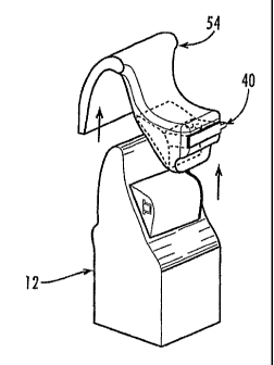
more offset from the tooth. But when the bracket 10 is used to form an
attachment 14
on the more vertically sloped lingual surface of the canine tooth 12 of FIG.
4, the
occlusal sidewall 20 is slightly offset from or adjacent to the tooth and the
gingival
sidewall 22 is more offset from the tooth. And in both cases, the rectangular
opening
18 is oriented level, that is, squared to horizontal and vertical, and
positioned spatially in
an ideal way for coordination with the adjacent brackets so that their
openings (and thus
the arch-wire that is later inserted into the openings) form a continuous and
smooth
arch at the conclusion of the orthodontic treatment. Furthermore, this
flexibility permits
using the same type of bracket 10 on other-sloped tooth surfaces, including at
higher or
lower positions of the same tooth and on different teeth. Details of the
preferred
methods of using the bracket 10 to form the attachment are provided below.
[00119] Referring to FIGS. 5A - 51, there are shown several of the possible
alternative embodiments of the bracket 10. FIG. 5A shows a bracket 10a
according to
a first alternative embodiment, in which the,fianges 26a' and 26a" of the body
16a have
notches 28a. The notches 28a reduce the tendency of fracture planes forming in
the
bonding material, thereby providing increased bonding strength. Towards this
end, the
notches can be deeper or shallower, greater or lesser in number, and/or made
in a
curved, triangular, squared, or other shape, as may be desired.
[00120] FIG. 5B shows a bracket 10b according to a second alternative
embodiment, in which the bracket body 16b and opening 18b are laterally
curved. In
this configuration, the curved opening 180 more closely conforms to the
curvature of
the arch of the teeth, which defines the curvature of the arch-wire. Thus,
when the wire
is installed in the opening 18b, it can curve slightly so that it does not
need such a sharp
21
CA 02670420 2009-05-22
WO 2007/067554 PCT/US2006/046427
bend upon exiting the opening at its ends. And the curved body can be rotated
slightly
at the mesial or distal end (about a vertical axis) to orient the opening
while maintaining
a low profile.
[00121] FIG. 5C shows a bracket 10c according to a third alternative
embodiment,
in which the bracket body 16c has two openings 18c. In this configuration, the
bracket
10c can be used to form attachments that make up a sectionalized orthodontic
appliance that accommodates the insertion of multiple wire segments, as will
be
described in more detail below.
[00122] FIG. 5D shows a bracket 10d according to a fourth alternative
embodiment, in which the bracket body 16d has no flanges. In this
configuration, the
bracket 10d has a low profile, with a width that is equal to the depth of the
opening 18d
plus the thickness of the distal sidewall 24d.
[00123] FIG. 5E shows a bracket 10e according to a fifth alternative
embodiment,
in which the bracket opening 18e is tubular and the bracket body 16e has four
sidewalls
defining the tubular opening. In this configuration, there is more bracket
body surface
area for bonding and a grasping clip can be more easily removed from the
opening
because the adhesive does not contact it. But the bracket 10e may not be quite
as low
in profile and may be more costly to manufacture. Accordingly, instead of the
tubular
opening 18e being completely closed, the fourth (tooth-side) sidewall may be
thin and
extend across the opening from the occlusal side but stop short of the
gingival side
(leaving a gap), thereby eliminating the width that would otherwise be added
by the
fourth sidewall.
[00124] FIG. 5F shows a bracket 10f according to a sixth alternative
embodiment,
in which the bracket opening 18f is tubular and the bracket body 16f has four
sidewalls
of generally uniform thickness defining the tubular opening.
[00125] FIG. 5G shows a bracket lOg according to a seventh alternative
embodiment, in which the bracket has retention flanges 26g with notched edges
28g.
[00126] FIG. 5H shows a bracket 10h according to an eighth alternative
embodiment, in which the bracket opening 18h has an open side unnotched
retention
flanges 26h.
[00127] FIG. 51 shows a bracket 10i according to a ninth alternative
embodiment,
in which the bracket retention flanges 26i with notched edges 28i.
22
CA 02670420 2009-05-22
WO 2007/067554 PCT/US2006/046427
[00128] In another aiternative embodiment, the bracket body has one or more
inner flanges for assisting in holding the bracket on a grasping clip. In yet
another
alternative embodiment, the bracket body has a lingual sidewall and gripping
arms
extending from opposite ends of it that together define the opening, with the
gripping
arms configured for holding the bracket on a grasping clip. In still another
alternative
embodiment, the bracket body is generally L-shaped and rests on a grasping
clip, with
or without gripping arms. In another alternative embodiment, the bracket body
is
generally triangular-shaped with the opening in the long side. In yet other
alternative
embodiments, the bracket has two openings that are aligned but with a gap
between
them, that are vertically overlapping and laterally staggered, or that are
stacked
horizontally. And in still another alternative embodiment, the bracket opening
is at the
gingival, occlusal, or lingual side of the bracket body.
[00129] Referring to FIGS. 6 - 8, there is shown an orthodontic bracket 110
according to a second exemplary embodiment of the present invention. While the
bracket 10 of the first exemplary embodiment is primarily for use on the
lingual surface
of incisors and other front teeth 12, the bracket 110 of the second exemplary
embodiment is primarily, but not exclusively, for use on the facial or lingual
surfaces of
molars and other back teeth 112. Because these surfaces are generally much
closer to
vertical than the lingual surfaces of incisors where the brackets 10 are
attached, the
bracket 110 has an opening 118 and flanges 126 that are configured
differently.
[00130] In particular, the opposing sidewalls that form the opening 118 have
the
same length, or about the same. And both the flanges 126 are swept back so
that they
curve back symmetrically as they extend away from the opening 118. In this
configuration, the bracket 110 can be positioned in a wide range of low
profile positions.
For example, FIG. 7 shows an orthodontic attachment 114 with the bracket 110
positioned adjacent a generally vertical surface,of a premolar tooth 112, and
FIG. 8
shows that same bracket positioned adjacent to a sloped surface of a molar
tooth. In
both cases, the bracket 110 and resulting attachment 114 are low profile, with
the
rectangular opening 118 still level and at a preferred spatial orientation.
[00131] FIGS. 9 and 10 show a bracket 110a according to a first alternative to
the
second exemplary embodiment, in which the bracket body 116a has two openings
118a. In this configuration, the bracket 110a can be used to form attachments
114a
23
CA 02670420 2009-05-22
WO 2007/067554 PCT/US2006/046427
that make up a sectionalized orthodontic appliance, as will be described in
more detail
below. It will be understood that the alternative features described above
with respect
to the first exemplary embodiment can be implemented as alternative
embodiments to
the second exemplary embodiment.
Orthodontic Attachments Made Using the Brackets
[00132] Referring back to FIG. 3, details of the orthodontic attachment 14
will now
be provided. The attachment 14 includes a mass of adhesive 30 bonded to the
tooth
12 and an orthodontic bracket 10 bonded within the adhesive mass. The adhesive
30
is preferably provided by a generally white-colored optically curable
compound. By
using an adhesive 30 with a color and translucency that resemble the color and
translucency of teeth, the attachment 14 is less noticeable. Alternatively,
the
attachment 14 may be formed using other bonding agents.
[00133] The bracket 10 is selected for forming the attachment 14 on a lingual
or
facial surface of the tooth 12, as desired. The attachment 14 is preferably
made using
one of the brackets 10 or 110 described herein. This way, the bracket 10 can
be
positioned offset from or adjacent to the tooth 12 while maintaining the
desired
orientation of the opening 18, so that the profile and visibility of the
resulting attachment
is minimized. Other types of brackets can be used, but to lesser advantage.
[00134] Preferably, the adhesive mass 30 encapsulates the bracket 10, except
for
the opening 18. In this configuration, the attachment 14 has a nice, smooth,
continuous
outer surface where the tongue and/cheeks might rub against it. Alternatively,
the
bracket 10 can be embedded in the adhesive mass 30, but not encapsulated, so
that a
portion of the body 16 remains exposed. In this configuration, the width of
the
attachment 14 is minimized. In any case, when using a bracket 10 with a
slotted
opening 18, the adhesive mass 30 defines a fourth wall of the opening.
Orthodontic Appliance Made From a Series of the Attachments
[00135] Turning now to FiG. 11, there is shown an exemplary embodiment of an
orthodontic appliance 34 made from a series of the attachments 14 and 114
mounted
on an arch of teeth 12 and 112, with arch-wires 36 routed through the openings
of the
attachments and secured in placed by, for example, composite stoppers (not
shown) at
24
CA 02670420 2009-05-22
WO 2007/067554 PCT/US2006/046427
the wire ends and/or at some point between the teeth. The figure shows the
teeth 12
and 112 after the appliance 34 has been used to reposition them to their
proper
positions. When the appliance 34 is initially installed, the attachments 14
and 114 are
not so nicely aligned and the wire 36 is not so nicely and smoothly arched.
Instead, the
initially bent wire 36 imparts forces to the nonaligned attachments 14 and
114, which in
turn pushes/pulls the teeth 12 and 112 towards the position in the figure.
[00136] In the embodiment shown, the appliance 34 includes six of the
attachments 14 on lingual surfaces of six anterior teeth 12 and two sets of
five of the
attachments 114 on facial surfaces of posterior teeth 112. in this way, the
appliance 34
is sectionalized into two back teeth sections that overlap with one front
teeth section to
simulate the effect of one continuous, straight wire. In this context,
"overlapping"
means that more than one of the appliance sections are present on a particular
tooth,
even if the sections each terminate shy of each other (so that a vertical line
can not be
drawn through them both). Preferably, the front teeth section overlaps with
the back
teeth sections, as shown, by virtue of at least one tooth (the canine in this
example)
possessing both facial and lingual attachments. Because the wire sections are
disconnected, the absolute vertical position of each wire section can thus
exist
independently of the absolute vertical position of the other sections allowing
more
flexibility in the vertical position of these sections. In other words,
bracket positions can
be coordinated within each section independently of the other sections, thus,
one
section may exist at a higher or lower position in relation to the other
sections. Also,
because the spatial position of the attachments can be highly customized with
precision
(using a precision positioning instrument), the attachments may be positioned
with the
higher degree of accuracy required to create a straight-wire system out of
disconnected
multiple sections of wire.
[00137] The appliance 34 is preferably made using the attachments 14 or 114
described herein, so that the appliance has a low profile and is, therefore,
not so
noticeable. In this way, one or more of the attachments can be formed having
their
brackets positioned adjacent to their corresponding teeth, and one or more
other of the
attachments can be formed having their brackets positioned offset from their
corresponding teeth, as may be needed to,make appliance have a smooth arch-
form to
CA 02670420 2009-05-22
WO 2007/067554 PCT/US2006/046427
minimize the bending needed in the wire. Other types of attachments and
brackets can
be used, but to lesser advantage.
[00138] FIG. 12 shows an alternative appliance 34a having three wire sections,
the first being eight of the attachments 14 on lingual surfaces of front teeth
12 teeth and
two sets of four of the attachments 114 on facial surfaces of back teeth 112.
Similarly,
FIG. 13 shows another alternative appliance 34b having five sections of wire,
ten of the
attachments 14 on lingual surfaces of front-most ten teeth 12, two sets of
four
attachments on the two premolar teeth with two single attachments placed on
the
lingual of first premolar teeth to serve as the anterior overlap point. Then
two sets of
three of the attachments 114 on facial surfaces of back teeth 112 including
another
overlap point on the second premolar that has both facial and lingual
attachments. And
FIG. 14 shows yet another alternative appliance 34c having various of the
attachments
all on lingual surfaces of the front and back teeth 12 and 112. In other
alternative
embodiments, the appliance can be formed using only single-opening
attachments,
only double-opening attachments, or any combination thereof, on only facial
tooth
surfaces, only lingual tooth surfaces, or any combination thereof. In other
alternative
embodiments, the appliance can be configured of as many or few overlapping
sections
as desired to simulate a continuous straight-wire system. Or the appliance may
be
configured with any combination of overlapping or non-overlapping sections,
with either
double- or single-tube attachments. Or, the appliance can be configured with
one or
multiple non-overlapping sections as deemed appropriate or possible for the
achievement of particular objectives in any particular case.
Grasping Clip for Positioning the Brackets
[00139] Turning now to FIGS. 15 -17, there is shown a grasping clip 40
according
to an exemplary embodiment of the present invention. The clip 40 is used to
hold the
bracket 10 in position while it is being bonded to the tooth or model 12. The
clip 40 is
intended primarily for use with brackets of the type described herein, though
it can be
used with other orthodontic brackets to some advantage. The clip 40 is
preferably a
unitary piece of molded plastic, though it can be made of other materials
using other
fabrication techniques.
26
CA 02670420 2009-05-22
WO 2007/067554 PCT/US2006/046427
[00140] The clip 40 has a finger 42 that it is received in the bracket opening
18
and a handle portion 44 for grasping. The finger 42 has a length that is equal
to or
greater than the length of the bracket opening 18 so that the finger extends
all the way
through the opening to prevent the adhesive from intruding into and blocking
the
opening (meaning preventing or hindering the routing of the wire through the
opening).
In a typical commercial embodiment, the finger 42 has a length that is greater
than
3mm, so that it can be used with brackets up to that length. Preferably, the
finger 42 is
configured so that it fits snugly in the opening 18. For example, the finger
42 may have
a cross sectional shape and a lateral curvature that conform to a cross
sectional shape
and a lateral curvature of the bracket opening. Thus, for use with the bracket
10b of
FIG. 5B, the finger 42 would preferably be rectangular in cross section and
laterally
curved. In this way, the clip 40 can be held by the handle portion 44 and the
clip will
support the bracket 10 securely in position so that it doesn't move while it
is being
bonded to one of the teeth.
[00141] The handle portion 44 is configured for being grasped by a person's
hand
and/or by a positioning tool 50 (see also FIG. 18). In this way, the bracket
10 can be
held in place while the orthodontist bonds it to the corresponding tooth.
[00142] In addition, the handle 44 is preferably keyed for use with a keyed
positioning tool, so that the clip 40 can be consistently aligned when
grasping it with the
positioning tool. For example, the handle 44 may have grooves 46 on both sides
for
receiving one or more ridges (not shown) on the positioning tool, or vice
versa, so that
the clip can be flipped either side up and still aligned and centered on the
positioning
tool.
[001431 ln alternative embodiments, the clip has a finger with a detent for
holding
the bracket on it, the -finger is keyed for use with matingly keyed bracket
openings for
centering or otherwise positioning the brackets on the clip, and/or the finger
has a thin
liner sleeve to which the adhesive bonds so that the sleeve tears away and
stays in the
bracket opening when the finger is removed. And in another alternative
embodiment,
the clip has two fingers for use with single- or double-opening brackets.
[00144] In another aspect of the present invention, there is provided an
orthodontic kit that includes a plurality of the orthodontic brackets and
grasping clips.
The kit is not shown in the figures separately from its constituent parts,
which are
27
CA 02670420 2009-05-22
WO 2007/067554 PCT/US2006/046427
individually described and shown. Preferably, the brackets and clips are of
any of the
types described herein, though other brackets and/or clips can be provided.
Method of Attaching the Brackets to Teeth to Form the Appliance (Method One)
[00145] Turning now to FIGS. 18 -- 23, there is shown a first exemplary method
of "
attaching the brackets 10 to teeth 12 to form the attachments 14 and
appliances 34.
The method includes creating a model 52 of the teeth 12, which can be done by
conventional techniques well known in the art, and providing orthodontic
brackets 10
with openings for the wire. Preferably, brackets 10 of the type described
herein are
used, though others can be used to obtain some of the benefits of the method.
Next,
the brackets 10 are positioned relative to the model teeth 52, for example,
with each
bracket positioned and held by a grasping clip 40, which is moved into
position and held
there by a positioning tool or device 50, as shown in FIG. 18. The positioning
tool or
device 50 is preferably of the type disclosed in U.S. Patent Application
Serial No.
10/750,194, filed on December 31, 2003, and entitled "Orthodontic Bracket
Positioning
Device And Method," which in its entirety is hereby incorporated herein by
reference.
Alternatively, the positioning tool or device may be of a conventional type
known in the
art, such as that disclosed by U.S. Patent No. 4,812,118 to Creekmore, which
in its
entirety is hereby incorporated herein by reference.
[00146] Alternatively, the brackets can be physically placed on a physical
model
using a robotic system such as those commercially offered by Staubli
Corporation (US
HQ - Duncan, South Carolina) or Nachi Robotic Systems, Inc. (US HQ - Novi,
Michigan). Such robotic systems include. a robotic arm controlled by
programmed
controllers. Robotic systems from both of these vendors were tested with
actual dental
models and brackets and proved to be of sufficiently high positional accuracy
to
perform the bracket placement. Using the robotic system to position the
brackets
requires more steps than using rapid prototyping (as described below), but to
date the
accuracy has been shown to be better for robots than for rapid prototyping.
lyt will be
understood that this robotic bracket-positioning step can be used with the
transfer tray
and clip described above for use in this method or with the modified transfer
tray and
clip described below in "method two."
28
CA 02670420 2009-05-22
WO 2007/067554 PCT/US2006/046427
[00147] The step of positioning the brackets 10 includes, for each of the
brackets,
positioning the bracket offset from or adjacent to the corresponding tooth 12,
as is
appropriate for that particular tooth, and preferably referencing relevant
anatomical
features of the particular tooth to determine its appropriate position and
coordinating the
position with other attachments of the relevant section. Also, this step may
include
positioning some of the brackets 10 at the lingual surfaces of the front teeth
12 and
positioning some of the brackets at the facial surfaces of the back teeth 112
in an
overlapping arrangement. In addition, the bracket openings are occluded to
prevent the
intrusion of adhesive, for exampie, by using a clip 40 that has a finger that
inserts into
the opening.
[00148] Next, the positioned bracket 10 is encapsulated and bonded to the
model
teeth, 52 with the adhesive 30, as shown in FIG. 19. Then a transfer tray is
formed
around the clips 40, brackets 10, adhesive encapsulation 30, and model 52
using an
impression material 54 such as a thermoplastic material, as shown in FIG. 20.
Next, the
transfer tray is removed. The mechanical interlocking of the tray impression
material
around the clips assists in breaking the bond of the adhesive to the model
teeth such
that the clips 40, the brackets 40, and adhesive 30 encapsulating them are
removed
from the model and are now contained in the impression material 54 in the
tray, as
shown in FIG. 21. The operator can assist breaking the bonds of the brackets
to the
model via insertion of an instrument underneath or through the tray material
to
mechanically force a breakage.
[00149] Next, the impression material/transfer tray 54, bracket 10, and
adhesive
encapsulation 30 are positioned on the patient's teeth 12 from which the model
teeth 52
were made, as shown in FIG. 22. Then the brackets 10 are bonded to the teeth
12
using an adhesive 30 (prior applied or newly applied), which may be the same
or a
different type from that used to bond the brackets to the model teeth 52. The
impression material/transfer tray 54 is then removed from the teeth 12,
leaving the
brackets, adhesive mass, and clips bonded to the teeth. The transfer tray
impression
material 54 can be easily pulled off the brackets 10 by hand. And the bracket
openings
are unoccluded, for example, by removing the clips, leaving the bracket
openings
unobstructed and ready to receive the wire through them. FIG. 23 shows a
completed
29
CA 02670420 2009-05-22
WO 2007/067554 PCT/US2006/046427
orthodontic attachment 14, with the adhesive material 30 encapsulating the
bracket 10
and bonded to the tooth, while the opening is unobstructed.
[00150] An alternative method of attaching the brackets 10 to teeth 12 to form
the
attachments 14 and appliances 34 is similar to the exemplary method described
above.
In this alternative method, however, the brackets 10 are encapsulated by
bonding the
brackets 10 to the model teeth 52 and, instead of encapsulating them with the
adhesive
30, applying removable shells 56 over the brackets, as shown in FIG. 24. The
shells 56
may be plastic or made of another material with sufficient rigidity that they
do not
compress when the impression material is applied to it. Then an impression is
made in
the impression material of the shell-encapsulated bracket, the impression
material and
shell-encapsulated bracket are removed from the model teeth, the shell is
removed
from the impression material, and the void left where the shell was is now
filled with the
adhesive material. Using this method, the resulting low profile cap over the
bracket is
very smooth and uniform so to be less noticeable to the user's tongue.
[00151] Another alternative method of attaching the brackets 10 to teeth 12 to
form the attachments 14 and appliances 34 is similar to the methods described
above.
In this alternative method, however, the brackets 10 are not encapsulated, but
are
merely embedded into a mass of the adhesive. In particular, after the bracket
10 is
positioned relative to the model teeth 52, a mass of the adhesive 30 is
applied to the
model teeth and the bracket is embedded into the mass and thereby bonded to
the
model teeth, as shown in FIG. 24. But the bracket 10 is not covered with the
adhesive
or otherwise encapsulated. The resulting attachment has a lower profile
because no
material is applied over the lingual side of the bracket. And because the
bracket 10 is
embedded in the adhesive 30, that is, the bracket is sunk at least somewhat
into the
adhesive mass, the resulting bond is strong. Of course, the brackets can be
bonded to
the teeth with the adhesive only being between the bracket and the tooth,
without being
encapsuiated or embedded into the adhesive, if that is desired in a given
case.
Method of Attaching the Brackets to Teeth to Form the Appliance (Method Two)
[00152] Turning now to FIGS. 26 - 56, there is shown a second exemplary
method of attaching orthodontic brackets 10 to teeth 12 to form the
attachments 14 and
the appliance 34. This method is similar to the first exemplary method
described
CA 02670420 2009-05-22
WO 2007/067554 PCT/US2006/046427
above, but uses modified brackets, clips, and transfer trays, and substantial
steps of
the process are automated. The modifications to the brackets, clips, and
transfer trays
are described below in the description of the method steps.
[00153] In particular, the method includes the following steps:
A. digitally positioning virtual orthodontic brackets and attachments on a
virtual
model of a patient's teeth;
B. digitally generating a virtual transfer tray for the virtual teeth model
and
attachments;
C. fabricating a physical transfer tray that is a replica of the virtual
transfer tray;
and
D. bonding the physical attachments onto the physical patient's teeth using
the
physical transfer tray.
[00154] It will be understood that the method may be implemented including all
or
oniy a portion of these steps, and that the method may be implemented
utilizing devices
and articles other than those particularly described herein. The steps will
now be
described in detail.
[00155] It should be pointed out that, as used herein, the term "virtual"
means
"simulated in electronic form by means of a computer or computer network." In
addition, where the terms bracket, attachment, clip, and transfer tray are
used herein
without the adjectives "virtual" or "physical," the intended meaning is a
physical
embodiment of the item, not a virtual one.
A. Digitally Positioning Virtual Orthodontic Brackets and Attachments
[00156] The first step is creating a three-dimensional (3D) digital
representation of
the patient's teeth. For example, FIG. 26 shows a screen shot of a 3D virtual
model 60
the patient's teeth. This step can be done by direct or indirect 3D scanning
methods
and systems.
[00157] In conventional indirect 3D scanning methods, a physical impression of
the patient's teeth is made using conventional materials and techniques well
known in
the art. For example, materials such as alginate or polyvinyisiloxane may be
used to
make the impression. Next, a physical model is made from the impression using
conventional methods and materials well known in the art. For example,
materials such
31
CA 02670420 2009-05-22
WO 2007/067554 PCT/US2006/046427
as Gypsum stone or plaster may be used to make the model. Then, a conventional
digital 3D scanner is used to scan the model and digitally generate the
virtual 3D model
60 of the patient's teeth. Alternatively, the impression itself can be
scanned, instead of
scanning a model made from the impression. The physical impression and model
are
typically made by the orthodontist and sent to a third party service provider
who scans
the physical model to create the virtual model 60. Then the service provider
stores the
virtual model 60 on a computer-readable medium so that it can be accessed by
the
orthodontist. For example, the virtual model 60 can be stored on a computer
server
that is connected to the Internet and accessible by the orthodontist, stored
on a
computer and emailed to the orthodontist, or it can be stored on a CD-ROM or
flash
memory device that is sent to the orthodontist by overnight delivery. If
desired, the
orthodontist can acquire a digital 3D scanning system and perform the scanning
in his
office. One such system and commercially available indirect scanning service
is
provided by CADENT, Inc. of Or Yehuda, Israel under the brand ORTHOCAD IQ.
[00158] In conventional direct 3D scanning methods, the virtual 3D model 60 of
the patient's teeth is digitally generated by scanning the teeth directly or
"intra-orally."
This technique eliminates the need to make the impression of the patient's
teeth and
the physical model from the impression. Several systems exist for making
direct intra-
oral scans. One such commercially available system is provided by ORAMETRIX,
Inc.
of Dallas, Texas under the brand SURESMILE. This system includes a scanner
that
requires coating the teeth with a powder to create a more opaque surface for
scanning.
Another such system has been demonstrated by CADENT, Inc. of Or Yehuda, Israel
under the brand ORTHOCAD. This intra-oral scanning system does not require
coating
the teeth with a powder and thus provides a more efficient scanning process.
[00159] Various other systems and devices for digitally creating the 3D
virtual
model 60 of teeth are disclosed in U.S. Pat. No. 6,099,314; U.S. Pat. App.
Pub. No.
US2006/0212260; U.S. Pat. App. Pub. No. US2006/0158665; and U.S. Pat. App.
Pub.
No. US2003/0160784, which are herein incorporated by reference. Various of
these
and other direct and indirect scanning systems and techniques are suitable for
use in
the present method, so long as the result is that the 3D virtual model 60
obtained is
suitable for use in the subsequent steps.
32
CA 02670420 2009-05-22
WO 2007/067554 PCT/US2006/046427
[00160] Referring now to FIGS. 27 - 35, once the 3D virtual model 60 has been
digitally generated, it is rendered into graphical form for display on a
computer screen.
The next steps are digitally rendering and positioning virtual brackets 62 on
the virtual
model, digitally rendering the virtual clips 68, digitally generating and
rendering virtual
attachments 64 including the virtual brackets encapsulated in a virtual
adhesive mass
72, and generating and rendering a virtual transfer tray 66 for the virtual
attachments.
These steps are typically done by the orthodontist in his office using
proprietary
software stored on a conventional computer having input devices (e.g.,
keyboard and
mouse) and an output device (e.g., a monitor). FIGS. 27 - 35 are screen shots
of the
orthodontist's computer display showing the virtual teeth 60, the virtual
brackets 62, the
virtual clips 68, the virtual adhesive mass 72, the virtual attachments 64,
and the virtual
transfer tray 66. Details of this proprietary software system are included in
co-owned
U.S. Pat. App. Ser. No. 10/ , filed on Dec. 5, 2006, and titled
"SYSTEM AND METHOD FOR POSITIONING ORTHODONTIC BRACKETS ON A
VIRTUAL MODEL OF A PATIENT'S TEETH.", An overview of the software will now be
provided.
[00161] The software functions to access and display the virtual model 60 of
the
patient's teeth, for example, by downloading it from the service provider's
server
computer, and to digitally generate and display the virtual brackets 62 with
openings 70,
attachments 64 with adhesive masses 72, transfer trays 66, and clips 68. The
virtual
brackets 62 with openings 70 and the virtual clips 68 are digital replicas of
the
corresponding physical ones, which are described in more detail below. And the
virtual
attachments 64 with adhesive masses 72 and the virtual transfer trays are
digitally
generated for subsequent use in making the corresponding physical ones, which
are
described in more detail below. The software includes a variety of novel tools
and
features for assisting the orthodontist (or other user) in the proper and
accurate
positioning of the virtual brackets 62. For example, the software preferably
functions to
display a menu of available sizes and configurations of the virtual brackets
62 and clips
68, and to permit the user to seiect the desired virtual brackets and clips to
be used
based on tooth type, size, position, etc.
[00162] In a typical commercial embodiment, the software implements one of two
different methodologies for determining coordinated positions of the virtual
brackets 62
33
CA 02670420 2009-05-22
WO 2007/067554 PCT/US2006/046427
to produce the desired treatment outcome. One methodology is mathematical and
the
other is a virtual "set-up" methodology.
[00163] When implementing the mathematical methodology, the software
functions to allow the user to select points, lines, or planes on the surface
anatomy of
each virtual tooth in the model 60, with each point, line, or plane
representing a
particular aspect the tooth anatomy. In addition, the software functions to
allow the
user to designate the value of certain angular or linear units of measure. The
software
then uses this information to determine the spatial position of the virtual
bracket 62 for
that virtual tooth. As an example, the user could select two points on each
tooth of the
virtual model 60 that represent the mesial and distal interproximal contact
points of the
tooth. The software then determines a particular orientation for each virtual
bracket 62
on each tooth so that the virtual bracket opening 70 parallels the lines
formed by these
selected points, and displays each virtual,bracket in the determined position
on the
virtual teeth 60. As another example, the user could select a point, line, or
plane, that
represents the location of the cusp tip (or incisal edge if an incisor) of a
tooth. In
addition, the user can input a linear distance and vector from this point,
line, or plane.
The software then determines the "vertical" position of the virtual bracket 62
relative to
the point, line, or plane. The software preferably functions to allow the user
to select
the point, line, or plane by clicking on displayed points, lines, and/or
planes, or by
plotting/drawing the point, line, or plane on the virtual model 60.
[00164] When implementing the virtual "set-up" methodology, the software
functions to allow the user to digitally manipulate each virtual tooth of the
virtual model
60 from its initial mal-aligned position to a position corresponding to the
desired
outcome of the treatment. The software functions to then allow the user to
position the
virtual brackets 62 on the well-aligned virtual teeth in an orientation such
that a virtual
non-deflected arch-wire in one plane (or segments of wire that simulate the
arch shape)
can pass through each of the virtual bracket openings 70. The position of each
of the
virtual brackets 62 relative to the corresponding virtual tooth 60 is
digitally retained,
while the software returns the virtual teeth to their original mal-aligned
positions in the
original virtual model. The software now displays the virtual model 60 of mal-
aligned
teeth with each virtual bracket 62 in its proper position.
34
CA 02670420 2009-05-22
WO 2007/067554 PCT/US2006/046427
[00165] Alternatively, the software can implement a combination of these two
methodologies to predict the outcome of treatment, and hence, the proper
positioning
of the virtual brackets 62. The user can use the mathematical component to
initially
position the virtual brackets 62. Then the software virtually rearranges the
virtual teeth
60 based on the initial position of each virtual bracket 62. The user can then
identify
flaws in the mathematical prediction and make adjustments using the virtual
"set-up"
component. It will be understood that other positioning methodologies can be
implemented by the software.
[00166] Regardless of the particular methodology implemented, the software
functions to allow the user to reference relevant anatomical features of the
virtual teeth
to determine their desired position and coordinate the position with adjacent
virtual
brackets, to manipulate the virtual brackets 62 with six degrees of freedom
but with no
part of the virtual brackets forming a lever arm against the virtual teeth 60,
to position
the virtual brackets suspended in free space (offset from or adjacent to the
lingual or
facial surfaces of the virtual teeth), and to display the virtual model of mal-
aligned teeth
with each virtual bracket in its proper position. FIGS. 27 - 29 show one of
the virtual
brackets 62 positioned relative to one of the virtual teeth 60, with the tooth
shown in an
"extruded" cross-section for simplification. These virtual brackets 62 are
virtual replicas
of the physical brackets 10 described in detail herein.
[00167] Once the virtual brackets 62 are positioned relative to the virtual
teeth 60,
the software functions to allow the user to add virtual occlusions to the
bracket
openings 70, for example, by using the virtual clips 68 that have a finger
that inserts
into the opening. As mentioned above, the software preferably displays a menu
of
available clip types, sizes, and configurations for the user to select from.
FIGS. 30 - 32
show one of the virtual clips 68 digitally slid onto one of the virtual
brackets 62 on the
virtual teeth 60, with the tooth shown in an "extruded" cross-section for
simplification.
The virtual clips 68 are virtual replicas of the physical clips 40 that engage
the physical
brackets 10 to assist in the process of transferring the physical attachments
14 to the
physical teeth 12 of the patient.
[00168] Once the virtual brackets 62 and clips 68 are in position, the
software
functions to allow the user to automatically or manually add the virtual
adhesive mass
72 for encapsulating or embedding the virtual attachments 64. FIG. 33 shows
one of
CA 02670420 2009-05-22
WO 2007/067554 PCT/US2006/046427
the virtual attachments 64 on one of the virtual teeth 60, with the virtual
bracket 62
offset from the tooth and thus suspended in free space. The virtual tooth 60
and the
virtual adhesive mass 72 of FIG. 33 are shown in an "extruded" cross-section
for
simplification-the virtual adhesive mass has a smoother contour than us
depicted.
B. Digitally Generating the Virtual Transfer Tray
[00169] Referring now to FIGS. 34 and 35, in the next step the software
digitally
generates the virtual transfer tray 66 based on the unique geometry of the
virtual teeth
60 and the particular shape and selected positions of the virtual attachments
64 and
clips 68. The virtuai transfer tray 66 is generated with a void 74 for
receiving the virtual
adhesive mass 72 and bracket 62, and with a slot 76 for receiving the virtual
clip 68.
The software generates the void 74 with a size, shape, and position for later
producing
a physical adhesive mass that will provide good strength and a smooth contour
for
patient comfort. Thus, preferably the void 74 is generally dome-shaped. The
software
generates the slot 76 with a size, shape, and position so that it holds the
virtual clip 68
in the position needed to hold the virtual bracket 62 in the selected position
suspended
in free space and offset from the virtual tooth 60. Details of the void, the
slot,
orientation features, and undercut management of the virtual transfer tray 66
are
provided below in the description of the physical transfer tray, which is a
replica of the
virtual one. In addition, the software preferably includes novel tools and
features that
permit the user to modify the design of the virtual transfer tray 66.
C. Fabricating the Physical Transfer Tray
[00170] In the next step of the method, a physical transfer tray 54 is made
that is a
physical replica of the virtual transfer tray 66. The physical transfer tray
54 is made to
hold the physical brackets 10, adhesive mass 30, and clips 40, and to fit them
onto the
physical teeth 12. It will be understood that, as used herein, the term "clip"
refers to any
occluding element that functions as described herein, including structures
that are not
clip-like, such as plugs or bars. Before describing the fabrication of the
physical
transfer tray 54, some structural details of the physical clips 40, brackets
10, and
transfer tray will be provided.
36
CA 02670420 2009-05-22
WO 2007/067554 PCT/US2006/046427
[00171] Referring now to FIGS. 36 - 41, the physical clips 40, brackets 10,
and
transfer tray 54 are similar to those described above and shown in FIGS. 15 -
17, 2 -
10, and FIGS. 20 - 22, respectively, but with a few modifications. It will be
understood
that preferable results are achieved by the method when using the physical
clips 40,
brackets 10, and transfer tray 54 described herein, but that other types of
these items
could be used with the method to obtain desirable benefits.
[00172] As shown in FIG. 36, each of the physical brackets 10 similarly has a
body 16 with an opening 18 for receiving the wire in it and with retention
flanges 26 for
distributing forces over a larger area of the adhesive. The physical bracket
10 does not
have a flat (or other-shaped) base with a broad surface area for bonding
directly to the
tooth and fixing the position of the opening, as do conventional orthodontic
brackets.
Instead, the physical bracket 10 can be positioned in free space with the
opening 18 at
a customized, pre-selected angle relative to the tooth surface, and can be
oriented with
six degrees of freedom, without any part of the body 16 creating a lever arm
against the
tooth surface. In this way, the physical bracket 10 can be oriented in a wide
range of
positions while maintaining a low profile and low visibility. Somewhat
differently from
the embodiments shown in FIGS. 5A - 5E, the physical bracket 10 depicted in
FIG. 36
is similar to that shown in FIGS. 5F - 51 in that it has more-uniformly thick
walls and a
more-rectangular shape so that it can be used on a wider range of tooth types
and
positions.
[00173] As shown in FIGS. 36 - 39, each of the physical clips 40 similarly has
a
finger 42 that it is received in the physical bracket opening 18 and a handle
portion 44
for grasping. To prevent the adhesive 30 from intruding into and occluding the
opening
(and thus to prevent or hinder later routing the wire through the opening),
the finger 42
has a length that is equal to or greater than the length of the physical
bracket opening
18 (the finger extends all the way through the opening) and the finger has a
cross-
sectional shape generally conforming to that of the bracket opening 18 (at
least it does
at the two ends of the bracket opening). Somewhat differently from the earlier-
described embodiments, the physical clip 40 depicted here has a reduced-
strength
zone 78 between the finger 42 and the handle 44 that fails when the finger is
subjected
to a shearing force, so that the finger breaks away from the handle (see also
FIG. 52).
37
CA 02670420 2009-05-22
WO 2007/067554 PCT/US2006/046427
For example, the reduced-strength zone 78 may be provided by a circumferential
channel or a notch in the finger.
[00174] FIGS. 39 - 41 show details of the physical transfer tray 54, and for
simplification depicts only a segment of the tray for holding one bracket. The
depicted
transfer tray segment is for a bottom arch of teeth, and a similar transfer
tray for the top
teeth is made in the same fashion with the only difference (other than the
customized
positions of the voids, slots, and attachment elements, as discussed below)
being that it
is inverted. The physical transfer tray 54 is preferably made of a translucent
plastic, as
described below, though other materials can be used.
[00175] In addition, the physical transfer tray 54 is designed to accommodate
undercut areas in its inner surface. For example, the tray material can be
selected for
having some resiliency to provide a limited degree of deflection, or the
software can be
programmed to design the tray without tray material in undercut areas or with
a thinner
wall in undercut areas to allow greater deflection of the tray. If the tray
material is too
rigid, the transfer tray may not deflect outward to get around a protruding
area of a
tooth to fit into an undercut underneath the protrusion. Current "undercut
strategy" in
the fabrication of a physical transfer tray is limited to either blocking out
recessed
undercut areas on the teeth model prior to fabricating the transfer tray or
eliminating
protruding undercut areas on the tray after fabrication. For practical
reasons, working in
the physical realm greatly limits the scope of any undercut strategy. However,
fabrication of the transfer tray in the virtual realm allows the opportunity
to control the
location and degree of undercut engagement, and the shape and thickness of the
material that will bend to engage the undercut. The shape and thickness of the
tray can
be optimized to produce a tray that will flex in the most favorable way
without breaking
(i.e. elastic deformation). A virtual tray can be designed with undercuts in
strategic
locations while undercuts in other areas (e.g., where there is severe mal-
alignment) are
completely eliminated.
[00176] Furthermore, the virtual transfer tray 54 can be digitally generated
with
novel features that are not generally practical to incorporate in typical
transfer trays
made from teeth impressions. One feature is that the virtual tray can be
provided with
holes strategically placed anywhere the operator identifies as a region where
there
might be a defect in the virtual teeth model. In this way, the operator avoids
later
38
CA 02670420 2009-05-22
WO 2007/067554 PCT/US2006/046427
creating a physical tray with a bulge that would prevent fully seating the
physical tray on
the physical teeth. Another feature is that the virtual tray can be provided
with holes
strategically placed in the tray to expose the tips of teeth. In this way,
when the
operator later seats the physical tray on the physical teeth, the operator can
easily see
the penetration of the teeth tips through the holes and thus verify that the
tray is fully
seated.
[00177] Because the physical transfer tray 54 is a physical replica of the
virtual
transfer tray 66, it has voids 84 for receiving the physical adhesive masses
72 and
brackets 10, and slots 86 for receiving the physical clips 40 with a snap fit.
For teeth
that are to have only a single bracket 10, the voids 84 and slots 86 are
provided in the
transfer tray 54 in a one-to-one relationship with the teeth, and for any
teeth that will
have two brackets there are two voids and slots for those teeth.
[00178] In the depicted embodiment, the segments of the transfer tray 54 have
a
continuous facial (outer/front) wall while the lingual (inner/rear) wall
defines partial gaps.
So when a series of the depicted segments are formed together, the completed
transfer
tray 54 has a continuous facial wall and a "scalloped" lingual wall with gaps
between
sections of the wall where the voids 84 and slots 86 are. In this way, the
transfer tray
54 is more flexible, which makes it easier to put on and take off of the
teeth, and the
slots 86 have at least one open side through which part of the clip extends,
which
makes it easier to move the bracket/clip 10/40 assemblies into and out of the
slots. In
addition, the teeth are mal-aligned at the start of the treatment program, and
the voids
86 and slots 86 are custom-oriented relative to the mal-aligned teeth, so the
transfer
tray 54 is custom-made with the void-defi,ning wall sections mal-aligned
relative to the
smooth arch desired at the conclusion of the treatment. In an alternative
embodiment,
the transfer tray has a continuous lingual wall.
[00179] Referring to FIGS. 37 - 41, the interrelationships between the
physical clip
40 and the physical transfer tray 54 will now be described. The physical clip
40
includes attachment elements 80 that engage mating attachment elements 82 of
the
physical transfer tray 54 to hold the c{ip, and thus the bracket 10, in the
precise position
determined in the bracket-positioning step. The attachment elements 80 and 82
may
be detents, male and female dimples, or ,other conventional structures that
cooperate to
provide a snap fit between two parts. Preferably, the size and shape of the
slot 86 are
39
CA 02670420 2009-05-22
WO 2007/067554 PCT/US2006/046427
selected (by the proprietary software discussed above) to generally conform to
the size
and shape of the clip 40 with the clip being slightly smaller so that the clip
is held in
place but can be readily inserted into and removed from the slot. To
facilitate inserting
and removing the clip 40 from the slot 86, they are tapered from larger at the
lingual
side of the transfer tray to smaller at the void 84. In addition, the void 84
is formed into
the inner surface of the physical transfer tray 54, and the slot 86 extends
through the
tray from the void to the outer surface of the tray. To prevent the
encapsulating
adhesive mass 30 from being forced out of the void 84 and into the slot 86 in
the latter
step of bonding the attachments 14 to the teeth 12, the physical clip 40 has a
mold
surface 88. When the physical clip 40 is inserted into the slot, the mold
surface 88
extends substantially across the slot where it meets the void, thereby
cooperating with
the void-defining inner surface 90 of the tray to form a continuous, smooth,
dome-like
surface. In- the depicted the physical clip 40, there is a gap 92 between the
finger 42
and the mold surface 88, and the mold surface is angled from vertical, which
makes this
embodiment well-suited for lingual placement.
[00180] As mentioned above, for different teeth sizes (e.g., youths, adults)
and
types (e.g., molars, incisors), different sizes and types of the brackets 10
may be
provided. To accommodate different sizes or shapes of bracket openings 18,
correspondingly different sizes or shapes of clips 40 are also provided, which
may in
some case also require the transfer trays 54 to be designed (using the above-
described
proprietary software) with correspondingly different sizes of slots 86. Thus,
in practice
the orthodontist may keep in the office (or order on a case-by-case basis) a
kit with a
variety of different brackets 10 and clips 40.
[00181] Having described details of the structure of the physical transfer
tray 54,
details of the step of fabricating it will now be described. As discussed
above, the user
(i.e., an orthodontist working in his/her office) first accesses (e.g.,
downloads via the
Internet) data representing the virtual model 60 of the patient's teeth or
generates the
data on-site, and then uses the software to digitally manipulate the data to
position the
virtual brackets 62 and to digitally generate the virtual transfer tray 66.
The orthodontist
then sends (e.g., via the Internet) the data representing the virtual transfer
tray 66 to a
third party service bureau or centralized facility at a remote location where
the data is
used to fabricate the physical transfer tray 54 out of a plastic or other
suitable material.
CA 02670420 2009-05-22
WO 2007/067554 PCT/US2006/046427
The physical transfer tray 54 is then sent (e.g., via overnight delivery) to
the
orthodontist's office for use. Alternatively, the fabrication of the physical
transfer tray 54
can be done on-site at the orthodontist's office.
[00182] In one aspect of the method of the invention, the physical transfer
tray 54
is fabricated by a conventional rapid prototyping machine. Rapid prototyping
is a group
of technologies that enable manufacturers and designers to fabricate parts
without the
need for expensive and time-consuming production molds. Rapid prototyping,
sometimes referred to as layered manufacturing or rapid manufacturing, takes a
computer file of a part, slices it into layers, and fabricates each layer one-
at-a-time,
stacking the layers until a complete 3D prototype is made. The advantages
include that
parts can be seen, felt, and tested before committing to expensive and time-
consuming
production molds. Thus, rapid prototyping is conventionally used to more-
efficiently
create and test prototype parts, not to fabricate production parts. The use of
rapid
prototyping in the present method is a novel application in several ways.
First of all, it is
used to produce custom physical orthodontic transfer trays 54 that are unique
to each
individual. Second, no physical mold is needed to make the physical transfer
trays 54.
Third, for indirect bonding, it eliminates the need for a precision placement
machine
(e.g., a robot) for placing the physical brackets 10, and it eliminates
several other steps
involved in the bracket positioning such as temporary bonding, fabricating an
RTV
transfer tray, and applying a clear RTV layer to the tray to allow for light
curing. And
fourth, the rapid-prototyped physical transfer trays 54 serve as a means of
custom-
positioning the orthodontic brackets 10 in the ideal anatomical location for
optimal tooth
repositioning unique to each individual's anatomy. That is, instead of using a
manual or
robotic bracket-placement system, the customized position of each bracket 10
is
designed into the rapid-prototyped transfer tray 54, which stores the precise
location of
the brackets relative to the individual's, specific tooth anatomy without the
brackets
actually touching the teeth. Various rapid prototyping methods and apparatus
are
disclosed in U.S. Pat. No. 7,128,866; U.S. Pat. No.6,261,077; U.S. Pat. No.
6,159,411;
U.S. Pat. No. 6,146,487; and U.S. Pat. No. 6,110,409, which are herein
incorporated by
reference.
41
CA 02670420 2009-05-22
WO 2007/067554 PCT/US2006/046427
D. Bonding the Physical Attachments onto the Physical Patient's Teeth
[00183] Now that the physical transfer tray 54 has been fabricated, it must be
prepared for use. The orthodontist or other user first assembles the physical
brackets
onto the physical clips 40 (see FIG. 36). Then the user grasps (manually or
with a
tool) the handles 44 of the clips 440 and inserts the physical bracket/clip
assemblies
10/40 into the slots 86 of the physical transfer tray 54 (see FIGS. 42 - 44).
Because of
the cooperating attachment elements 80 and 82 of the clips 40 and the tray 54,
the
bracket/clip assemblies 10/40 are held in the precise position set when using
the
software to design and generate the virtual transfer tray, with the bracket
suspended in
free space within the void 84 (see FIGS. 40 and 41). As such, the spatial
orientation of
the bracket 10 is not dependent on the tooth's surface anatomy. Alternatively,
these
transfer tray preparation steps may be done by another party such as the third
party
service bureau who fabricates the physical transfer tray 54.
[00184] Referring to FIG. 45, in the next step the orthodontist or other user
fills
each void 84 of the physical transfer tray 54 with the adhesive (e.g., a light-
cured,
composite resin) until it encapsulates the bracket 10, which remains held
precisely in
position in the void by one of the clips 40. The voids 84 preferably are not
filled with the
adhesive until the patient is in the orthodontist's office to have the
orthodontic
attachments 14 put on. Preferably, the voids 84 in the tray 54 are over-filled
with
adhesive to ensure a complete bond to the tooth 12 and complete formation of
the
domed adhesive mass 30, which is defined by the dome-shaped void-defining
inner tray
surface 90 and the mold surface 88 of the clip 40. Depending on the particular
adhesive used, the teeth 12 may need to be prepared as prescribed by the
provider of
adhesive.
[00185] Referring to FIGS. 46 -49, the orthodontist or other user then seats
the
prepared physical transfer tray 54 onto the patient's physical teeth 12. As
shown in
FIG. 48, if there are any undercut areas on the transfer tray 54 that could
prevent
proper seating on the teeth, the tray will deflect (see the directional
arrows) to
accommodate the undercut areas. As shown in FIG. 49, because the void 84 was
overfilled, the excess adhesive 94 will "ooze" out from the tray 54, and the
user can
then remove this excess adhesive 94 before curing.
42
CA 02670420 2009-05-22
WO 2007/067554 PCT/US2006/046427
[00186] Referring to FIG. 50, the adhesive mass 30 is then cured so that it
bonds
to the tooth 12. For example, when using a conventional dental, light-cured,
composite
resin adhesive and a translucent transfer tray, the adhesive mass 30 is cured
by using
a light source (e.g., a conventional dental blue light-emitting. diode). The
blue LED is
used to direct the blue light 96 through the translucent tray 54 and onto the
adhesive
mass 30 to cure it. Of course, other types of adhesives can be used, and
accordingly
other types of curing methods can be used.
[00187] The next step in the method is to remove the transfer tray 54 from the
teeth 12. As shown in FIG. 51, the user pulls the transfer tray 54 off of the
teeth 12. As
shown in FIG. 52, this imparts a shearing force on the fingers 42 of each of
the clips 40
(because the fingers are still in the openings 18 of the brackets 10 of the
attachments
14, which are now bonded to the teeth 12), thereby causing the reduced-
strength zones
78 to fail so that all of the fingers break off. In an aiternative embodiment,
a release
mechanism is built into the tray design that allows the entire clip to break
out of the
bottom of the tray. As shown in FIG. 53, this leaves only the attachments 14
(with the
fingers 42 still in the openings 18 of the brackets 10 of the attachments),
which do not
pull away from the teeth 12 with the transfer tray 54 because the adhesive
masses 30
have been bonded to the teeth. If there are any undercut areas on the transfer
tray 54
that could prevent or hinder removal of the transfer tray 54, the tray will
deflect to
accommodate this (see again FIG. 48). It should be noted that the adhesive
mass 30
as depicted is generally semi=cylindrical for ease of illustration, but in
practice it is
preferably dome-shaped with a smooth contour.
[00188] The next step is to remove the fingers 42 from the openings 18 of the
brackets 10 of the attachments 14. This can be done by pushing out the fingers
42
using a conventional dental tool 98, as shown in FIG. 54. This leaves only the
attachments 14 (the brackets 10 encapsulated in the adhesive mass 30) on the
teeth
12, as shown in FIG. 55, with the bracket opening 18 unobstructed throughout
its
length.
[00189] As shown in FIG. 56, the final step is to thread the wire 36 through
the
openings 18 in the brackets 10 to form the. completed appliance 34 (see FIGS.
11-14).
In the depicted embodiment, a straight rectangular wire 36 is inserted into
the
rectangular opening 18 of a single bracket, 10 on a single tooth 12. At the
beginning of
43
CA 02670420 2009-05-22
WO 2007/067554 PCT/US2006/046427
the orthodontic treatment program, adjacent teeth 12 are mal-aligned and so
their
brackets 10 are also mal-aligned. As such, the first wire 36 inserted is
typically a small
cross-section, round, highly flexible, highly resilient wire capable of large
deflection that
imparts a comparably low force upon this large degree of deflection (these
qualities are
found in conventional orthodontic wires made of nickel-titanium alloys and
copper-
nickel-titanium alloys, among others). Later in the treatment program,
rectangular,
larger-diameter wires may be installed, as needed for the desired treatment
outcome.
[00190] In an alternative method of the invention, the brackets engage (e.g.,
by
snapping) directly with attachment elements formed in the transfer tray, and
the bracket
openings are occluded by plugs or other occlusion elements-for keeping the
adhesive
out of the bracket openings, thereby eliminating the need for the clip. For
example,
attachment elements (e.g., male dimples) can be designed into the transfer
tray using
the proprietary software so that the dimples engage attachment elements (e.g.,
female
dimples) of the bracket, thereby holding the bracket in the transfer tray.
[00191] In another aspect of the invention, these attachment elements are
designed to both hold the bracket and to occlude the bracket openings. For
example,
attachment elements (e.g., rectangular male dimples) can be designed into the
transfer
tray using the proprietary software so that the dimples snap into both open
ends of the
rectangular bracket opening, thereby orienting and holding the bracket in the
transfer
tray and at the same time occluding the bracket opening. As another exampie, a
small
section of flat wire made of SLA may be suspended across each of the voids in
the
transfer tray, from one side of the_void to the other, where the bracket
opening needs to
be. Then one of the brackets is slid onto each wire to both hold the brackets
in place
and occlude the bracket openings from filling with the adhesive.
[00192] In yet another aspect, the invention includes a kit with the items
described
herein for use with the method described herein. In this aspect, the invention
includes
a kit with a number of the brackets and clips.
[00193] In view of the foregoing, it will be appreciated that various aspects
of the
present invention provide advantages over conventional orthodontic brackets,
attachments, appliances, and methods of orthodontic treatment using these
elements.
These advantages include, but are not limited to, the provision of a base-
independent
bracket system that eliminates the lever-arm effect and thereby allows for
effectively
44
CA 02670420 2009-05-22
WO 2007/067554 PCT/US2006/046427
unlimited customization of bracket opening orientation while maintaining the
lowest
possible attachment profile.
[00194] In addition, the innovative bracket system and positioning method
eliminates the need for an open-faced slot in the attachments and instead
provides a
bracket that is used to form an attachment with a close-faced opening.
Therefore, no
tie wings and thus no ligature ties are needed, so the brackets have a lower
profile and
are smoother. Furthermore, because a closed-faced system possesses limitations
on
the degree of wire bends that can be placed, this then requires a high degree
of
precision positioning of the attachments to minimize the need for such bends
and thus
to minimize the need for manual adjustments by the operator and thus provide
for much
more efficient and less costly treatment and less stress for doctor, and
reduced
treatment time. Moreover, the lack of tie-wings and ligature ties allows for
far less
friction which permits more efficient translation of forces to teeth, which in
turn permits
easier sliding, which results in higher efficiency.
[00195] Furthermore, aspects of the present invention provide for precise
coordination of over-lapping wire segments to create a "simulated-continuous"
wire
system. 'This overcomes the problem 'of needing a large wire bend at the
canine-
premolar in the traditional lingual methods-therefore, one creates a useable
straight-
wire system on the lingual side with a minimal bracket profile height and
maximum
smoothness. For example, the first premolar could receive two attachments (or
one
double-opening attachment) on the lingual side to serve as the overlap point
for
creating the simulated continuous wire mechanical system. This permits the use
of
straight wire segments exclusiveiy theoretically an entire arch could be
composed of
multiple two-tooth segments that alternate between facial and lingual (or they
could be
all on the lingual or all on the facial using a double-opening attachment). In
addition,
this permits using anterior attachments on the lingual side of anterior teeth
and
posterior attachments on the facial side of posterior teeth, with one tooth on
each side
being the point of overlap and having both a facial and lingual attachment.
Furthermore, this permits the use of different horizontal planes for each wire
segment-
one can be placed higher, the other lower.
[00196] Moreover, the anterior lingual application of the attachments provides
additional advantages. The anterior attachments can be placed on the lingual
side of
CA 02670420 2009-05-22
WO 2007/067554 PCT/US2006/046427
the teeth to keep them out of sight. The small profile of the attachments
maintains
patient comfort. And the smooth surface of the encapsulated attachments
further
enhances patient comfort. Finally, an appliance including the lingual and
facial
attachments of the size, shape, and position as proposed can be maintained in
place
following active therapy to serve as a semi-permanent fixed retainer. This
type of fixed
retainer would be unique in that the wire can be removed while leaving the
attachments
in place. As such, the wire can be removed to facilitate cleaning by the
patient and can
be replaced with a new or the same wire. This type of fixed retainer would
also be
unique in that the same appliance serves as both the treatment mechanism and
the
retainer mechanism. This eliminates the need for fabrication of an additional
retainer
appliance at the completion of active therapy. Furthermore, any fixed retainer
has the
advantage of not requiring compliance by the patient (unlike a removable
retainer that
requires the patient remember to wear it) and the advantage of being more
comfortable
and attractive than removable appliances that are visible on the facial side
and
generally quite bulky.
[00197] It is to be understood that this invention is not limited to the
specific
devices, methods, conditions, and/or parameters described and/or shown herein,
and
that the terminology used herein is for the purpose of describing particular
embodiments by way of example only. Thus, the terminology is intended to be
broadly
construed and is not intended to be limiting of the claimed invention. In
addition, as
used in the specification including the appended claims, the singular forms
"a," "an,"
and "the" include the plural, plural forms include the singular, and reference
to a
particular numerical value includes at least that particular value, unless the
context
clearly dictates otherwise. Furthermore, any methods described herein are not
intended to be limited to the sequence of steps described but can be carried
out in
other sequences, unless expressly stated otherwise herein.
[00198] Moreover, whiie certain embodiments are described above with
particularity, these should not be construed as limitations on the scope of
the invention.
It should be understood, therefore, that the foregoing relates only to
exemplary
embodiments of the present invention, and that numerous changes may be made
therein without departing from the spirit and scope of the invention as
defined by the
following claims.
46