Note: Descriptions are shown in the official language in which they were submitted.
CA 02670520 2009-05-25
WO 2008/062322 PCT/IB2007/004343
1
CATAMENIAL AND SANITARY TAMPONS
CROSS-REFERENCE TO RELATED APPLICATIONS
[0001] This Application claims the benefit of U.S. Provisional Application No.
60/860,798, filed November 24, 2006; U.S. Provisional Application No.
60/880,023, filed
January 12, 2007; U.S. Provisional Application No. 60/898,710, filed February
1, 2007; U.S.
Provisional Application No. 60/920,776, filed March 30, 2007; U.S. Provisional
Application
No. 60/907,411, filed April 2, 2007; and U.S. Provisional Application No.
60/929,490, filed
June 29, 2007, the entire contents of each are hereby incorporated by
reference.
BACKGROUND
[0002] This disclosure is generally related to the field of catainenial and/or
sanitary
tampons and to devices permitting absorption of the body's natural waste
fluids.
[0003] Many sanitary articles exist, especially for absorbing menstrual
fluids, in
particular catamenial and/or sanitary tampons made of absorbent material in
the form of
sheets and/or bands that are folded and/or rolled up, using techniques well
known to persons
skilled in the art, in order to form tampons that are inserted, with or
without applicators, into
the vaginas of the users.
[0004] However, although there are many models made of various materials and
with
absorption capacities that vary according to the particular requirements and
losses, problems
associated with leaking and/or soiling still exist that are due either to
absorption capacities
that are too low or to problems of volume, or even poor adherence to the
vaginal wall, or a
drainage phenomenon due in particular to the withdrawal devices, namely the
threads and/or
strings designed to remove the used tampon.
[0005] A problem also exists at the moment of withdrawal when the withdrawal
devices, namely the threads and/or strings designed to remove the used tampon,
and the
vaginal wall can exert a pressure on the tampons and cause drying, which leads
to a flow of
fluid that soils the user's hands. Moreover, given that the lower part of the
tampon, also
called the proximal part, is greatly enlarged, this part has a tendency to
cause discomfort or
injuries by rubbing on the vaginal wall, especially in the area of muscular
narrowing of the
vaginal wall.
[0006] Many devices have already been proposed. For example, patent
application
WO 2006/094753 discloses a tampon with an impermeable zone formed by a plastic
film,
and zones of variable absorption in order to avoid drying of the vaginal
walls. Moreover,
U.S. Patent No. 3,693,622 discloses tampons and other sanitary articles which,
at their ends,
coinprise zones impregnated with fluid-repelling compositions.
[0007] The devices described in these documents nevertheless have numerous
disadvantages, such as the possibility of the fluid-repelling compositions
migrating into the
CA 02670520 2009-05-25
WO 2008/062322 PCT/IB2007/004343
2
whole of the tampon and/or the sanitary article after production, the
possibility of the fluid-
repelling compositions being transferred to the user's finger at the moment of
insertion of the
tampon, and especially the impossibility of limiting the drying effect during
withdrawal.
Moreover, the disclosed devices do not solve the problem of the shaping and
adaptation of a
tampon such that it better matches the shape of the vaginal walls.
[0008] U.S. Patent No. 7,060,057 discloses tampons comprising nonabsorbent
zones
arranged on the outer surface of the tampon that permit increased comfort at
the interface
between the tampon and the vaginal walls.
[0009] U.S. Patent No. 7,097,638 discloses tampons comprising zones that form
reinforcements on the outer walls of the tampon in order to improve comfort
while at the
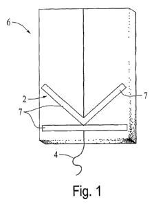
same time maintaining the absorption capacities of the tampons.
[0010] U.S. Patent No. 3,965,905 discloses tampons formed of a plurality of
absorbent product parts comiected by a withdrawal cord.
[0011] These different devices, however, do not significantly improve
absorption
while at the same time improving comfort and retaining other important
properties. The
tampon described in U.S. Patent No. 3,965,905, for example, does not provide a
tampon that
is sufficiently cohesive to permit its insertion without an applicator.
[0012] U.S. Patent Application Publication No. 2003/0097108 describes a tampon
comprising an absorbent compressed body whose outer face is largely covered by
an
absorbent sliroud that forms a skirt beyond the proximal end of the body of
the tampon.
[00131 U.S. Patent Application Publication No. 2005/0096620 describes a tampon
obtained by rolling up a layer of absorbent material, the layer having an edge
intended to
constitute the proximal end after rolling, and being covered by an absorbent
shroud before
rolling.
[0014] U.S. Patent No. 4,211,225 describes a tampon permitting improved
comfort
during its withdrawal. For this purpose, a first shroud and then a second
shroud are attached
to the body of the tampon and are fixed in the area of the distal end of the
tampon. The first
shroud is designed such that the frictional forces generated during withdrawal
between the
body of the tampon and the first shroud are less than the frictional forces
between the second
shroud and the surrounding tissues.
SUMMARY
[0015] The present disclosure relates to a catamenial or sanitary tampon with
an
absorbent body, where the tampon comprises means for limiting the expansion
and/or the
absotption of at least one zone of the body of the tampon when the tampon
comes into
contact with a fluid that is to be absorbed.
[0016] Thus, the control of the expansion and/or of the absorption of the body
of the
tampon in this zone permits formation, at this location, of a fluidic barrier
that is more or less
CA 02670520 2009-05-25
WO 2008/062322 PCT/IB2007/004343
3
iinpervious with respect to the absorbed fluid. In some embodiments, the body
of the tampon
may comprise a plurality of zones formed by fluidic barriers.
[0017] In embodiments, the expansion and/or absorption are limited by a solid
hydrophobic substance whose melting point is greater than 37 C, which
partially or totally
impregnates the absorbent inaterial fiom wliich the tampon is made.
[0018] The disclosure is also directed to tampons having a withdrawal thread
that is
also at least partially impregnated with a solid hydrophobic substance whose
melting point is
greater than 37 C.
[0019] By using a solid hydrophobic substance whose melting point is greater
than
37 C, the zones in which the expatision and/or the absorption are limited are
permanent, that
is to say, the zones are nondeformable or are only minimally deformable, even
when the
tampon is saturated.
[0020] A solid hydrophobic substance wllose melting point is greater than 37 C
may
have certain properties that are similar to those of beeswax, that is to say a
substance whose
plasticity permits malleability at room temperature, whose viscosity is low
when the
substance is melted, and that is totally hydrophobic.
[0021] In embodiments, the hydrophobic substance is chosen from the group
consisting of hydrogenated and/or nonhydrogenated petrolatum, paraffin and/or
stearin. In
embodiment variant, the hydrophobic substance is hydrogenated petrolatum.
[0022] In embodiments, the hydrophobic substance is chosen from the group
cbnsisting of hydrogenated and/or nonhydrogenated oils and/or fats.
[0023] In einbodiments, the hydrophobic substance is chosen from the group
consisting of natural and/or synthetic waxes, for example carnauba wax, jojoba
oil, hard
paraffin and so-called microcrystalline wax (waxes extracted from petroleum),
and silicone
waxes (waxes obtained by syntllesis). In embodiments, the hydrophobic
substance is
beeswax. Beeswax is principally composed of an ester of ethylene glycol and
two fatty acids.
In other embodiments, the hydrophobic substance is camauba wax.
[0024] The disclosure is also directed to a tampon configured so that the part
in which
the expansion and/or the absorption are limited is situated at the proximal
end of the tampon.
[0025] In embodiments, the part in which the expansion and/or the absorption
are
limited is situated at a distance of more than 0.5 mm froin the proximal end
of the tampon.
[0026] In embodiments, the zone in which the expansion and/or the absorption
is
limited forms a spiral inside and outside the tampon.
[0027] In embodiments, the tampon additionally comprises another zone in which
the
expansion and/or the absoiption are limited, situated half way between the two
ends of the
tampon.
[0028] In embodiments, the tampon additionally comprises another part in which
the
expansion and/or the absorption are limited, forming a spiral outside the
tampon. In such
embodiments, and in contrast to the tampon described and shown in EP 1 383
453, the spiral
CA 02670520 2009-05-25
WO 2008/062322 PCT/IB2007/004343
4
shape obtained may be nondeformable or only minimally deformable, even after
saturation of
the tampon with a hydrophilic substance, and this spiral shape makes it
possible to channel
the flow and thus avoid flow of fluid along the vaginal walls, and also to
increase the time of
contact between the absorbent material and the flow, thus permitting improved
absorption
and a greater capacity of the tainpon.
[0029] The tampons may be impregnated with the solid hydrophobic substance
whose
melting point is greater than 37 C in the melted state and before and/or after
formation of the
tainpon. When the substance is applied before formation of the tampon, it is
applied to the
band before folding and/or compression and/or rolling of the band.
[0030] A zone formed by a line measuring several tenths of a millimeter to
several
millimeters is applied continuously or discontinuously to the front face
and/or rear face of the
band, optionally in several zones, and optionally nonsymmetrically. The zones
of
impregnation may be arranged on what will become the lower part, middle part,
and/or the
upper part of the tampon in order to create one or more reservoirs with these
successive
barriers.
[0031] The zones may be arranged in such a way that, after folding and/or
compression of the band, a spiral shape is obtained that is nondeformable or
only minimally
deformable, even after saturation of the tampon with a hydrophilic substance.
This spiral
shape makes it possible to channel the flow, and thus avoid flow of fluid
along the vaginal
walls, and also to increase the time of contact between the absorbent material
and the flow,
thus improving absorption and capacity of the tampon.
[0032] In embodiments, the tampon comprises an impregnation zone in the form
of
an upturned funnel which, by diverting the flow from the center of the tampon,
makes it
possible to avoid accumulation of fluid at the site of fixation of a
withdrawal thread and to
avoid leaks due to the presence of this withdrawal thread.
[0033] In embodiments, the means for limiting the expansion and/or the
absorption
are formed by at least one restriction member encircling the corresponding
zone of the body
of the tampon, while allowing the zone to be maintained in its initial shape
when the body of
the tampon inflates under the effect of the absorption.
[0034] In embodiments, the restriction member may be made in the form of a
ring, a
washer, a string, a collar, or one or more foldable restrictor bands made of
permeable
material.
[0035] In embodiments, the restriction member comprises, on its outer face, at
least
one smooth zone that makes it possible to limit the friction during removal of
the tampon, so
as to avoid any injury.
[0036] In embodiments, the restriction member has a spiral shape either on the
distal
part of the tampon or on the proximal part of the tampon.
[0037] Advantageously, the ring is formed with the protector of the tampon.
CA 02670520 2009-05-25
WO 2008/062322 PCT/IB2007/004343
[0038] In embodiments, each restrictor band comprises at least one orifice
near each
of its two ends, the orifice having a diameter that is substantially equal to
that of the
compressed tampon. Where appropriate, the restrictor band may comprise at
least a third
orifice in the central part for passage of the witlldrawal thread.
[0039] In embodiments, the tampon comprises at least two superposed restrictor
bands arranged perpendicular to each other before folding.
[0040] In embodiments, the restrictor band is designed to have a length that
ensures
the restrictor band does not disturb the natural development of the geometry
of the tampon
body when the tampon is placed in contact with a fluid that is to be absorbed.
[0041] The disclosure also relates to a strip of absorbent material comprising
zones in
which the absorbent material is partially or totally impregnated with a solid
hydrophobic
substance wllose melting point is greater than 37 C.
[0042] The disclosure is also directed to a method for producing a tampon,
wherein
the method finally comprises, after a step of folding and/or of compression
and/or of
impregnation of an absorbent material such as an absorbent strip including a
hydrophobic
substance, a step of heating to a temperature above the melting point of the
hydrophobic
substance, making it possible to bind the impregnated zones.
[0043] The disclosure is also directed to a tampon comprising a saturation
indicator at
its proximal end. In embodiments, the indicator is formed by the proximal zone
situated at
the proximal end of the tampon comprising at least one zone in which the
expansion and/or
the absorption are limited, the zone being formed by partial or total
impregnation of the
absorbent material of the tampon with a solid hydrophobic substance whose
melting point is
greater than 37 C. In embodiments, the indicator is formed by the proximal
zone situated at
the proximal end of the tampon comprising at least one zone in which the
expansion and/or
the absorption are limited, the zone being formed by placement of a
restriction member, for
example in the form of a ring, string, collar or restrictor band(s) encircling
the tampon and
allowing it to be maintained in its initial shape in the zone in question,
when the tampon
comes to inflate under the effect of the absorption. The various embodiments
may be
separate or in combination wit11 one or more of the other embodiments.
BRIEF DESCRIPTION OF THE DRAWINGS
[0044] Embodiments will be better understood from the detailed description
given
below and by reference to the attached drawings, in which:
[0045] Figures 1 and 2 are diagrammatic views of two strips of absorbent
material;
[0046] Figures 3 and 3a are diagrammatic views of two other strips of
absorbent
material during the injection of the hydrophobic substance;
[0047] Figure 4 is a diagrammatic view of another strip of absorbent material
when
laid out flat;
CA 02670520 2009-05-25
WO 2008/062322 PCT/IB2007/004343
6
[0048] Figures 5 and 5a are diagrammatic views, in longitudinal section, of a
tampon
according to the embodiment of Figure 16 before and after heating of the
hydrophobic
substance;
[0049] Figure 6 is a diagrammatic view of the machine for producing a tampon
according to the embodiment of Figure 16;
[0050] Figures 7 and 8 are diagrammatic views of a first strip of absorbent
material
and of a second strip of absorbent material, respectively, when laid out flat;
[0051] Figures 7a and 8a are perspective views of the tampons obtained
respectively
from the strips of absorbent material shown in Figures 7 and 8;
[0052] Figure 9 is a diagrammatic view of a third strip of absorbent material;
[0053] Figures 10, 11 and 12 are diagraminatic views of a fourth strip of
absorbeilt
material, a fift11 strip of absorbent material and a sixth strip of absorbent
material,
respectively, when laid out flat;
[0054] Figures 10a, 11 a and 12a are perspective views of the tampons obtained
respectively from the strip of absorbent material shown in Figures 10, 11 and
12;
[0055] Figure 13 is a diagrammatic view of another strip of absorbent material
when
laid out flat;
[0056] Figure 13 a is a perspective view of the tampon obtained from the strip
of
absorbent material shown in Figure 13;
[0057] Figure 14 is a diagranunatic view of four other illustrative
embodiments of a
strip of absorbent material;
[0058] Figures 15 and 15a are diagrammatic perspective views of two tampons
according to the embodiment of Figure 16 during the phase of injection of the
hydrophobic
substance;
[0059] Figures 16 and 16a are diagrammatic perspective views of a tampon
according
to an embodiment, before use (Figure 16) and after use (Figure 16a);
[0060] Figure 17 is a diagrammatic view of a traditional tampon and Figure 17a
is a
diagrammatic view of a tampon according to the embodiment of Figure 16 during
the
withdrawal phase;
[0061] Figure 18 is a diagrammatic view of a tampon according to another
embodiment;
[0062] Figure 18a is a diagrammatic view of a tampon according to another
embodiment;
[0063] Figures 19 and 19a are partial diagrammatic views, in longitudinal
section, of
two separate rings with which a tampon according to the embodiment of Figure
18 is
equipped;
[0064] Figure 20 is a diagrammatic end view of a restriction member in the
form of
one or more washers;
CA 02670520 2009-05-25
WO 2008/062322 PCT/IB2007/004343
7
[0065] Figures 20a and 20b are diagrammatic perspective views of another
tampon
equipped with restriction meinbers shown in Figure 20, before and after use;
[0066] Figure 21 is a diagrammatic end view of a restriction member in the
form of
another type of washer;
[0067] Figure 21 a is a diagrammatic perspective view of another tampon
equipped
with a restriction member shown in Figure 21;
[0068] Figure 22 is a diagrammatic end view of a restriction member in the
forin of
another type of washer;
[0069] Figure 22a is a diagrammatic perspective view of another tampon
equipped
with a restriction member shown in Figure 22;
[0070] Figure 22b is a diagrammatic perspective view of the withdrawal thread
with
which the tampon shown in Figure 22a is equipped;
[0071] Figures 23 and 23a are diagrammatic views of a restrictor band forming
a
restriction member, before folding (Figure 23) and after folding (Figure 23
a);
[0072] Figure 24 is a diagrammatic flat view of another restrictor band
forming a
restriction member;
[0073] Figure 24a is a diagrammatic perspective view of another tainpon
equipped
with the restrictor band shown in Figure 24;
[0074] Figure 25 is a diagrammatic flat view of a restrictor band forming a
restriction
member;
[0075] Figure 25a is a diagrammatic view, in longitudinal section, of another
restrictor band forming a restriction member;
[0076] Figures 25b and 25c are diagrammatic perspective views of another
tampon
equipped with the restrictor band shown in Figure 25, before and after use;
[0077] Figure 26 is a diagrainmatic perspective view of another restrictor
band
forming a restriction member, after folding;
[0078] Figure 27 is a diagrammatic view of the placement of the restriction
member,
shown in Figure 23 a, around a tampon;
[0079] Figure 27a is a diagrammatic perspective view of the tampon shown in
Figure
27, once the restriction member is in place;
[0080] Figure 27b is a view similar to Figure 27a, after use;
[0081] Figure 28 is a diagrammatic perspective view of a tainpon as shown in
Figure
27a, additionally comprising a fluidic barrier formed with the aid of a
hydrophobic substance;
[0082] Figure 29 is a diagrammatic end view of an orifice according to another
embodiment;
[0083] Figures 30 and 31 are diagrammatic views of two other restriction
members
that are cross-shaped; and
[0084] Figure 32 is a diagrammatic perspective view of a tampon with a
saturation
indicator.
CA 02670520 2009-05-25
WO 2008/062322 PCT/IB2007/004343
8
DETAILED DESCRIPTION OF EMBODIMENTS
[0085] In the following detailed description of the figures defined above, the
same
elements, or the elements performing identical functions, will keep the same
reference
numbers, so as to make various embodiments easier to understand. For example,
reference
number 1 is given to any tampon according to one embodiment, and reference
number 10 is
given to any tampon according to a second embodiment of the invention.
[0086] Tampons 1 are obtained from strip of absorbent material 6, such as are
shown
in Figures 1 and 2.
[0087] The form of the impregnation zone is specially designed as a function
of the
desired result.
[0088] In Figure 1, the impregnation zone forms a funnel 2 which channels the
flow
toward the proximal end of the tampon 1 and, for example, avoids the
peripheral leaks due to
the flow passing to the zone of contact between the walls (not shown) and the
tampon 1.
[0089] In Figure 2, the impregnation zone is an upturned funnel 2' which, by
diverting the flow from the center of the tampon 1, avoids accumulation of
fluid at the site of
fixation of the withdrawal thread 4 and avoids leaks due to the presence of
the withdrawal
thread 4.
[0090] Figures 3 and 3 a show examples of injectors 5 for injecting a
hydrophobic
substance 7 into the thickness of a strip of absorbent matei7al 6, the
injection being carried
out from the side.
[0091] After formation of the tampon 1, the zones of impregnation may be
heated to
temperatures above the melting point of the hydrophobic substance 7, so as to
cause the
hydrophobic substance 7 to melt and to better connect or affix the various
layers that were
saturated.
[0092] Figure 4 shows a strip of absorbent material 6 that will form a tampon
I by
means of folding or compression. The hydrophobic substance 7 is applied in the
transverse
direction on one face, or on both faces and, if appropriate, within the
thickness of the strip of
absorbent material 6.
[0093] Figures 5 and 5a show a schematic view of a folded tampon 1, with the
points
of application of the hydrophobic substance 7. Depending on the stage of
formation of the
tampon 1, the points of hydrophobic substance 7 may be joined to one another,
for example
by thermofusion at the time of folding, rolling and/or packaging, or may
remain free.
[0094] The spacing, and hence the barrier and/or filter effect, is quantified
by the
intensity of the heating and also by the thickness of the impregnation and,
consequently, by
the quantity of hydrophobic substance 7 applied.
[0095] Thus, the parts that are not in direct contact with this strong heat
source will be
joined to a lesser extent to one another. The effect of this is to create
passages that will slow
the downward movement of the blood and will thus make it possible to increase
the
absorption time and capacity of the tampon 1 by an effect of filtration and
deceleration of the
CA 02670520 2009-05-25
WO 2008/062322 PCT/IB2007/004343
9
flow, thereby making it possible to increase the time of contact between the
flow and the
absorbent material from which the tampon is made.
[0096] Moreover, it must be clearly understood that the dilation and/or
expansion of
the proximal part is able to be controlled in terms of time. The dilation
and/or expansion is
able to be produced with a delay effect, or may even be rendered impossible,
depending on
the quantity of the hydrophobic substance, the temperature of the latter, and
the temperature
during the step of thermofusion used in its production.
[0097] Methods for the production of a tampon 1 may further comprise, after a
step of
folding, and/or of compression and/or of impregilation, a heating step that
makes it possible
to bind the impregnated zones.
[0098] A tampon 1 may be produced using a machine 8 suc11 as that shown
schematically in Figure 6. More particularly, this machine 8 serves as a
support for injecting
the strip of absorbent material 6 with hydrophobic substance 7 on one of the
two faces, or
botli of them, or within the thickness of the strip of absorbent material,
with the aid of the
injectors 5 that are connected to an injection device 7' for the hydrophobic
substance 7.
These injectors 5 are either single or multi-directional. For injections into
the thickness of the
strip of absorbent material 6, the injectors 5 are equipped with needles that
penetrate the strip
of absorbent material 6, as illustrated in Figures 3 and 3 a. The injectors 5
may be of the
traditional pump type, which may be mounted on an "XY" table to configure the
forms. The
injectors 5 are optionally mobile, in order to apply the hydrophobic substance
7 by creating
forms such as those illustrated in Figures 1, 2, 7-10, and 13.
[0099] The path traveled by the strip of absorbent material 6 from its arrival
at Dl to
the outlet D3 makes it possible to lengthen the time between the application
of the
hydrophobic substance 7 and the zone of assembly of the tampon 1, and thus
permits
stiffening of the hydrophobic substance 7. In embodiments, a jet of air may be
applied to
accelerate this stiffening. One observes at D2 a flexion in the strip of
absorbent material 6 to
control the traction of the strip of absorbent material 6, and at D3 the exit
of the strip of
absorbent material 6 for entry into the following assembly machine.
[0100] The hydrophobic substance 7 may also be placed in a very precise manner
such that it is located only inside the tampon 1 at the time the latter is
rolled up or folded, and
not on the visible outer part of the tampon 1. The barrier is located inside
the tampon 1, and
the first layer will permit absorption of the lateral leaks flowing along the
wall.
[0101] Different application variants are illustrated in Figures 7 to 12.
Figures 13 to
15a schematically illustrate the results obtained and the methods of
impregnation.
[0102] The application may be carried out on the tampon 1 when already fonned,
the
melted hydrophobic substance 7 thus being applied with an injection or
impregnation system,
after protection of the zones that are not to be iinpregnated on the tampon I
already formed.
[0103] It is also possible to soak the withdrawal thread 4 in the operating
mode, either
before being assembled or during the phase with the tampon 1.
CA 02670520 2009-05-25
WO 2008/062322 PCT/IB2007/004343
[0104] A strip of absorbent material 6 of absorbent material may comprise
zones in
which the absorbent material is partially or totally impregnated with a solid
hydrophobic
substance 7 whose melting point is greater than 37 C. For example, the
hydrophobic
substances described herein may have a melting point equal to or greater than
38 C, 39 C,
40 C, 41 C, 42 C, 43 C, 44 C, 45 C, or 46 C. In embodiments, the hydrophobic
substance
has a melting point equal to or greater than 47 C, 49 C, 51 C, 53 C, 55 C, 57
C, 59 C,
61 C, or 63 C. In embodiinents, the hydrophobic substance has a melting point
equal to or
greater than 68 C, 69 C, 70 C, 71 C, 72 C, 73 C, 74 C, 75 C, or 76 C.
[0105] The hydrophobic substances preferably do not dissolve in bodily fluids
and
preferably have a melting point that is higher than the internal temperature
of the human body
(37 C) so that the hydrophobic substance remains solid while the tampon is in
a vagina.
Preferably, the hydrophobic substance has a melting point that is 45 C or
higher so that the
hydrophobic substance remains solid during shipping and/or storage of the
tampons where
the tainpons may be exposed to temperatures greater or significantly greater
than 37 C.
However, it is preferred that the melting point of the hydrophobic substance
does not exceed
120 C, and more preferably does not exceed 100 C, thus making it more
economical to
manufacture the tampons in tenns of costs and time. The lower the melting
temperature of
the hydrophobic substance, the less energy and time required to melt the
hydrophobic
substance for impregnation of the absorbent material and to allow or cause the
impregnated
hydrophobic substance to solidify.
[0106] In embodiments, the hydrophobic substance 7 impregnated on the strip of
absorbent material 6 is chosen from the group consisting of hydrogenated
and/or
nonhydrogenated oils and/or fats.
[0107) In embodiments, the hydrophobic substance 7 impregnated on the strip of
absorbent material 6 is chosen from the group consisting of natural and/or
synthetic waxes.
[0108] In embodiments, the hydrophobic substance 7 impregnated on the strip of
absorbent material 6 is hydrogenated petrolatum.
[0109] In embodiments, the hydrophobic substance 7 impregnated on the strip of
absorbent material 6 is beeswax.
10110] In embodiments, the hydrophobic substance 7 impregnated on the strip of
absorbent material 6 is camauba wax.
[0111] The mode of functioning of the absorption of the tampon 1 is
illustrated in
Figures 16, 16a and 17a. The absorption is improved by the barrier effect
provided by the
impregnation with the hydrophobic substance 7. This therefore makes it
possible to reduce
the first leaks. The zones that are impregnated are nondeformable or are
minimally
deformable, and they are not expanded, or are only minimally expanded, by the
absorption of
the flow of fluid. Moreover, such a tampon 1 may be designed to have an
improved fluid
absorption capacity of up to about 60%.
CA 02670520 2009-05-25
WO 2008/062322 PCT/IB2007/004343
11
[0112] As is shown more specifically in Figure 17, a traditional tampon 30
will tend
to allow an untimely quantity of blood to escape via the proximal end and the
withdrawal
thread, on account of pressure exerted on the tampon by the muscles near the
vaginal opening
during removal of the tampon 30. This pressure is represented schematically by
the white
arrows in Figure 17. By contrast, a tampon 1 configured with a fluidic barrier
formed by a
liydrophobic substance 7 as disclosed herein and as shown in Figure 17a,
counteracts this
phenomenon by reducing the amount of blood that flows into the proximal area
of the tampon
during withdrawal of the tampon.
[0113] When the impregnation is partial and/or the tampon 1 does not undergo
heating after formation of the tampon 1 with preimpregnated strip of absorbent
material 6,
and/or after the impregnation, the barrier formed simply has a filtering
effect and makes it
possible to increase the absorption by increasing the contact time between the
flow and the
absorbent material from which the tampon 1 is made. I
[0114] According to a second einbodiinent of a tampon 10, the means for
limiting the
expansion and/or the absorption are formed by at least one restriction member
11 encircling
the corresponding zone of the body and allowing the zone to be maintained in
its initial shape
when the body comes to inflate under the effect of the absorption. This
restriction member
11 may, for exainple, be in the form of a ring, a string or a collar
encircling the body of the
tampon 10, as is illustrated in Figure 18.
[0115] In an embodiment, the zone that is coinpressed or whose expansion
and/or
absorption are limited, functions as a means of reducing the passage of the
fluid. The zone
has a spiral shape either on the distal part of the tainpon 10 or on the
proximal part of the
tampon 10.
[0116] In anotller embodiment, the restriction member 11 may be formed with a
string, where at least a portion of the string is wrapped, tied, fastened, or
otherwise affixed
around the body of the tampon. As shown schematically in Figure 18a, a
withdrawal thread
4 may also be connected to and/or function as the restriction member 11.
[0117] In another embodiment, the ring forming the restriction member 11 may
be
formed with the protector 12 or packaging of the tampon 10, such as a wrapper,
which is cut
or pre-slit or breakable so that the ring is separable from the protector 12
or packaging of the
tampon 10, as is illustrated in Figures 19 and 19a.
[0118] This protector 12 has a tab 12' for guaranteeing the protection of the
ring 11
intended to remain in place after the insertion. During use of the tampon 10,
the user takes
hold of this tab 12' in order to fragment the protector 12 at the area of two
weld points or
bonding points 12". The ring 11 will then be formed by the remaining part of
the protector
12 around the tampon 10.
[0119] Moreover, and as is shown in Figure 19a, the tab 12' may be reattached
to the
protector 12 via weld points or bonding points 12"'. This variant is
particularly
CA 02670520 2009-05-25
WO 2008/062322 PCT/IB2007/004343
12
advantageous from the point of view of hygiene, because the ring 11 is free of
any prior
contact with the exterior before detachment of the protector 12.
[0120] The position of the ring 11 may be centered with respect to the distal
and/or
proximal ends and/or offset toward one of the ends.
[0121] As is shown in Figures 20 and 20a, the ring may be fonned by a single
washer
14 or by a plurality of stacked washers 14, such as 2, 3, 4, 5, 6, 7, 8, 9, or
10 or more washers.
The orifice of each washer 14 has a diameter substantially equal to that of
the coinpressed
body of the tampon 10. Figures 20a and 20b show a ring having four stacked
washers 14.
[0122] As is shown in Figure 21, the orifice of each washer 14 is preferably
formed
by making two slits 14' perpendicular to each other, the effect of which is to
delimit four
substantially triangular flaps 14" which are oriented upward or downward
depending on
whether the washer 14 is introduced via the top or bottom of the tampon 10.
However, the
orifice may be formed by two slits that are not perpendicular to each other,
or by more than
two slits. In Figure 21 a, the washer 14 has been slid on from the bottom of
the tampon 10.
The washers 14 may be secured to the tampon by affixing one or more of the
triangular flaps
14" to the tampon by hot pressing, hot melting, sewing, or any other method,
as
schematically depicted by the dashed lines in Figure 21 a.
[0123] Moreover, as is shown in Figure 22, two opposite flaps 14" may each
comprise a hole 14"' in such a way as to allow the passage of the withdrawal
thread 4 shown
in Figure 22b. In Figure 22a, the washer 14 thus formed has been slid on from
the top of the
tampon 10.
[0124] Referring to Figures 23 to 31, it is noted that each restriction member
may be
made of a perineable material in the form of a restrictor band 16 or in the
form of a cross 17
prior to folding.
[0125] More precisely, a restrictor band 16 for the upper part of the tampon
10 has at
least one nondeformable or minimally deformable orifice 18 near each of its
two ends, and
the diameter of this orifice 18 is chosen such as to be equal to that of the
body of the
compressed tampon 10. Thus, once the tampon 10 is in place, the body of the
tainpon will
inflate under the effect of the absorption, while the zone of the body of the
tampon encircled
by the edge of the orifices 18 will remain compressed. These orifices 18 may
therefore
actually play the role of a restriction member, prohibiting the tampon 10 from
changing
diameter in the desired zones.
[0126] As is shown more specifically in Figures 23 and 24, the restrictor band
16 has
a supplementary central orifice 18 when it is a restrictor band intended for
the lower part of
the tampon 10 and requiring passage of the withdrawal thread 4.
[0127] It inust also be clearly understood that the same restrictor band 16
may be used
for the lower part and the upper part of the tampon 10, as is shown in Figures
24 and 24a.
The restrictor band 16 in this case comprise four orifices 18, 18a, 18b, and
18c.
CA 02670520 2009-05-25
WO 2008/062322 PCT/IB2007/004343
13
[0128] By contrast, the tampon 10 shown in Figure 25b comprises a restrictor
band
16, illustrated in Figure 25, that has been folded and then inserted
exclusively via the upper
part of the tampon 10. Figure 25c shows the tampon 10 after use.
[0129] Another restrictor band 16 according to embodiments, as shown in Figure
25a,
differs from the one described above in that it comprises, on the one hand, an
inner absorbent
layer 16a and, on the other hand, an outer impermeable layer 16b connected to
the inner layer
16a.
[0130] As is shown in Figure 26, the restrictor band 16 may be formed by
folding in
an accordion configuration.
[0131] As is shown in Figure 27, the restrictor band 16 is folded in such a
way as to
align the orifices 18, with a view to then being positioned around the tampon
10, either via
the top or via the bottom of the tampon 10, by inserting the body of the
tampon 10 through
the orifices 18. In Figure 27a, this restrictor band 16 is thus introduced via
the bottom of the
tampon 10.
[0132] Advantageously, and as is shown in particular in Figure 27a, the
restrictor
band 16 is preferably long enough to leave enough "slack" such that the tampon
10 can
dilate. After use, and as is shown in Figure 27b, the restrictor band 16 will
enclose the
tampon 10 at the bottom part. In this embodiment, reduced or no friction
occurs in the area
of the vaginal wall during spasms. Indeed, the slight movement of translation
of the tampon
due to each spasm does not cause any movement of the restrictor band 16 itself
because of
the "slack," wliich allows the restrictor band 16 to remain motionless in
relation to the
vaginal wall. Furthermore, withdrawal of the tampon is easier because it
happens
schematically in two steps due to the "slack." In other words, the "slack" in
the restrictor
band 16 allows some freedom of movement of the body of the tampon with respect
to the
restrictor band 16. Tlius, when withdrawing the device, the body of the tampon
will move
first until it has been moved a sufficient distance that the "slack" in the
restrictor band 16 is
taken up, whereby the movement of the body of the tampon exerts enough tension
on the
restrictor band 16 that the body of the tainpon and the restrictor band 16
move relative to the
walls of the vagina at an equal rate. Also, the pulling force on the body of
the tampon
elongates the tampon in the axial direction, which decreases the radial
diameter of the body
of the tampon. As a result, the body of the tampon exerts less radial force on
the restrictor
band 16, which reduces the frictional force between the walls of the vagina
and the restrictor
band 16. Accordingly, the longitudinal forces that inust be applied to the
tampon to withdraw
the device are lower than those required with a traditional tampon.
[0133] For still greater efficacy, it must be clearly understood that the
limitation of
the expansion and/or of the absorption of one or more zones of a tampon 20
according to the
invention is able to be obtained by simultaneous use, as shown in Figure 28,
of a fluidic
barrier 7', formed with the aid of a hydrophobic substance 7, and also of a
restriction member,
such as a restrictor band 16. The fluidic barrier 7' and the zone formed by a
restriction
CA 02670520 2009-05-25
WO 2008/062322 PCT/IB2007/004343
14
member may be located in a proximate area of the tampon, and may be located at
substantially the same distance from the proximal end of the tampon.
[0134] As is shown in Figure 29, each orifice 18 of the restrictor band 16 may
be
fomled by making two slits 18' perpendicular to each other, the effect of
which is to delimit
four substantially triangular flaps 18" which is oriented upward or downward
depending on
whether the orifice 18 is introduced via the top or via the bottom of the
tampon 10. However,
the orifice may be formed by two slits that are not perpendicular to each
other, or by more
than two slits. A restrictor band 16 may be secured to the tampon by affixing
one or more of
the triangular flaps 18" to the tampon by hot pressing, hot melting, sewing,
or any otlier
method.
[0135] Of course, the material used to forin the restrictor band 16 is chosen
to be able
to resist the pressure of the tampon 10, 20 in the area of the orifices 18.
[0136] In the case where the restriction member has the form of a cross 17,
each of
the four ends comprises an orifice 18, as is illustrated in Figure 30. If it
is a restriction
member for the lower part of the tampon 10, a supplementary central orifice 18
is formed for
passage of the withdrawal thread 4, as shown in Figure 31.
[0137] It must also be clearly understood that this cross 17 may alternatively
be
produced with the aid of two separate restrictor bands 16 that are superposed
in the area of
their central parts and are arranged perpendicular to each other. In the case
where this cross
17 is arranged in the lower part of the tampon, the central orifices 18 of the
two restrictor
bands 16 are superposed in such a way as to permit passage of the withdrawal
thread 4.
[0138] The restriction member, whether in the form of a restrictor band 16 or
a cross
17, is designed to provide some "slack," such that it is able to adapt to the
geometry of the
body once it has developed in shape under the effect of the inflation
associated with the
absorption of the fluid, as is illustrated in particular in Figures 24 and
24a. For this reason,
the tampon 10 is able to deploy fully in the upper part without being impeded
by the restrictor
band 16 or cross 17 arranged around it.
[0139] Generally speaking, increasing the number of orifices 18 makes it
possible to
reduce the stresses that have to be withstood by each orifice 18.
[0140] In embodiments, the tampon comprises a saturation indicator at its
proximal
end. A saturation indicator is understood as a means allowing the user to
verify the state of
saturation or nonsaturation of the tampon by simple contact.
[0141] As is illustrated in Figure 32, the proximal zone 21 situated at the
proximal
end of the tampon 1 comprises at least one zone in which the expansion and/or
the absorption
are limited, this zone being formed by partial or total impregnation of the
absorbent material
of the tampon 1 with a solid hydrophobic substance 7 whose inelting point is
greater than
37 C. This proximal zone 21 may then serve as a saturation indicator zone.
[0142] In fact, because of the presence of the zone in which the expansion
and/or the
absorption are limited, the proximal zone 21 is soaked only when the tampon 1
is saturated.
CA 02670520 2009-05-25
WO 2008/062322 PCT/IB2007/004343
This proximal zone 21 may thus be used as a saturation indicator. If the
proximal zone 21 is
neither soaked nor inflated then this indicates to the user that the tampon 1
is not saturated.
[0143] In embodiments, the tampon 10 illustrated in Figure 17 is notable in
that the
saturation indicator is formed by the proximal zone 22 situated at the
proximal end of the
tampon 10 comprising at least one zone in which the expansion and/or the
absorption are
limited by placement of at least one restriction member 11, for example in the
form of a ring,
string, collar or one or more restrictor bands encircling the zone of the body
of the tampon
and allowing it to be maintained at this location in its initial shape when
the body of the
tampon inflates under the effect of the absorption.
[0144] Although the invention has been described in connection with particular
illustrative embodiments, it will be clear that it is not in any way limited
to these
embodiments and that it covers all the technical equivalents of the means
described, and their
combinations, insofar as these come within the scope of the invention.