Note: Descriptions are shown in the official language in which they were submitted.
. . ... .. . . . ...~ ... . _... ... .. . . ... . .. .... ....... ..... . . .
.
CA 02670856 2009-06-30
TITLE
VOLUMETRIC MICROPUMP
FIELD OF THE INVENTION
[0001] The present invention relates, in general, to drug delivery systems
and, more
particularly, to a communications system for a drug delivery device that may
be remotely
controlled. The present invention also relates to methods of assembling such a
drug
delivery device in a manner that improves reliability, accuracy and drug
delivery in the
device.
BACKGROUND OF THE INVENTION
[0002] Diabetes mellitus is a chronic metabolic disorder caused by an
inability of the
pancreas to produce sufficient amounts of the hormone insulin so that the
metabolism is
unable to provide for the proper absorption of sugar and starch. This failure
leads to
hyperglycemia, i.e. the presence of an excessive amount of glucose within the
blood
plasma. Persistent hyperglycemia causes a variety of serious symptoms and life
threatening long term complications such as dehydration, ketoacidosis,
diabetic coma,
cardiovascular diseases, chronic renal failure, retinal damage and nerve
damages with the
risk of amputation of extremities. Because healing is not yet possible, a
permanent
therapy is necessary which provides constant glycemic control in order to
always maintain
the level of blood glucose within normal limits. Such glycemic control is
achieved by
regularly supplying external insulin to the body of the patient to thereby
reduce the
elevated levels of blood glucose.
[0003] External insulin was commonly administered by means of multiple, daily
injections of a mixture of rapid and intermediate acting insulin via a
hypodermic syringe.
While this treatment does not require the frequent estimation of blood
glucose, it has been
found that the degree of glycemic control achievable in this way is suboptimal
because the
delivery is unlike physiological insulin production, according to which
insulin enters the
bloodstream at a lower rate and over a more extended period of time. Improved
glycemic
control may be achieved by the so-called intensive insulinotherapy which is
based on
multiple daily injections, including one or two injections per day of long
acting insulin for
providing basal insulin and additional injections of rapidly acting insulin
before each meal
CA 02670856 2009-06-30
in an amount proportional to the size of the meal. Although traditional
syringes have at
least partly been replaced by insulin pens, the frequent injections are
nevertheless very
inconvenient for the patient, particularly those who are incapable of reliably
self-
administering injections.
[0004] Substantial improvements in diabetes therapy have been achieved by the
development of the insulin infusion pump, relieving the patient of the need
syringes or
insulin pens and the administration of multiple, daily injections. The insulin
pump allows
for the delivery of insulin in a manner that bears greater similarity to the
naturally
occurring physiological processes and can be controlled to follow standard or
individually
modified protocols to give the patient better glycemic control.
[0005] Infusion pumps can be constructed as an implantable device for
subcutaneous
arrangement or can be constructed as an external device with an infusion set
for
subcutaneous infusion to the patient via the transcutaneous insertion of a
catheter or
cannula. External infusion pumps are mounted on clothing, hidden beneath or
inside
clothing, or mounted on the body and are generally controlled via a user
interface built-in
to the device.
[0006] Regardless of the type of infusion pump, blood glucose monitoring is
required to
achieve acceptable glycemic control. For example, delivery of suitable amounts
of insulin
by the insulin pump requires that the patient frequently determines his or her
blood
glucose level and manually input this value into a user interface for the
external pumps,
which then calculates a suitable modification to the default or currently in-
use insulin
delivery protocol, i.e. dosage and timing, and subsequently communicates with
the insulin
pump to adjust its operation accordingly. The determination of blood glucose
concentration is typically performed by means of a measuring device such as a
hand-held
electronic meter which receives blood samples via enzyme-based test strips and
calculates
the blood glucose value based on the enzymatic reaction.
[0007] Since the blood glucose meter is an important part of an effective
glycemic control
treatment program, integrating the measuring aspects of the meter into an
external pump
or the remote of a pump is desirable. Integration eliminates the need for the
patient to
carry a separate meter device, it offers added convenience and safety
advantages by
eliminating the manual input of the glucose readings, and may reduce instances
of
incorrect drug dosaging resulting inaccurate data entry.
2
CA 02670856 2009-06-30
Summary of the Invention
[0008] In one aspect, there is provided a volumetric micropump, comprising:
a flexible reservoir for containing a quantity of fluid; and
a stepped piston pump for withdrawing fluid from the flexible reservoir and
delivering fluid to an outlet,
wherein the stepped piston pump comprises a pumping chamber having an inlet
and an
outlet, the inlet being in fluid communication with the flexible reservoir and
having a
check valve to inhibit the entry of fluid into the flexible reservoir from the
pumping
chamber, the outlet being in fluid communication with a medical infusion
device and
having a check valve disposed therein for inhibiting the entry of fluid into
the pumping
chamber, and a piston, a variable portion of which is disposed in the pumping
chamber for
controlling the volume of the fluid withdrawn from the flexible reservoir and
ejected via
the outlet to the medical infusion device.
Brief Description of the Figures
[0009] The accompanying drawings, which are incorporated herein and constitute
part of
this specification, illustrate presently preferred embodiments of the
invention, and,
together with the general description given above and the detailed description
given
below, serve to explain features of the invention (wherein like numerals
represent like
elements), of which:
[0010] Figures lA-1C are cross-sectional views of a pump engine, according to
an
embodiment described and illustrated herein. Figure 1 A illustrates the entire
pump engine,
while Figures 1 B and 1 C illustrate a portion of the pump engine during a
pump cycle.
[0011] Figures 2A-2C are cross-sectional views of a stepped piston, which can
be used in
embodiments of the present invention, such as the pump engine illustrated in
Figures 1A-
1C.
[0012] Figure 3 is a cross-sectional view of a pump engine with a stepped
piston,
according to an embodiment described and illustrated herein.
3
CA 02670856 2009-06-30
[0013] Figures 4A-4C are cross-sectional views of a pump engine, according to
an
embodiment described and illustrated herein. Figure 4A illustrates the pump
engine at rest,
while Figures 1 B and 1 C illustrate the pump engine during a pump cycle.
[0014] Figures 5A-5C are perspective and cross-sectional views of a pump
engine,
according to an embodiment described and illustrated herein. The pump engine
has
minimal dead volume, and creates a continuous flow path at its full stroke
position.
[0015] Figure 6 illustrates a pump engine, with minimal dead volume, coupled
to a
reservoir and infusion set, according to an embodiment described and
illustrated herein.
[0016] Figures 7A-7B are perspective views of a pump engine with actuator,
according to
an embodiment described and illustrated herein.
[0017] Figures 8A-8E are perspective and cross sectional views of an outlet
check valve,
according to an embodiment described and illustrated herein.
[0018] Figures 9A-9B are perspective views that illustrate a method for making
a
support/elastic membrane assembly as illustrated in Figure 8D, according to an
embodiment described and illustrated herein.
[0019] Figures 10A-10B are perspective and cross sectional views of a check
valve,
according to an embodiment described and illustrated herein. The check valve
can be used
as an inlet check valve, or an outlet check valve.
[0020] Figures 11 A-11 C are perspective and plan views of a mechanically
activated valve,
according to an embodiment described and illustrated herein. The mechanically
activated
valve is typically placed inside a pump chamber, and can be used as an outlet
valve in any
of the pump engines described and illustrated herein.
[0021] Figures 12A-12B are perspective and cross sectional views of a check
valve,
according to an embodiment described and illustrated herein. The check valve
can be
placed between a pump chamber and a reservoir, or between a pump chamber and
an
infusion set. The check valve can be used with any of the pump engines
described and
illustrated herein.
[0022] Figure 13 is a cross sectional view of a pump engine, according to an
embodiment
described and illustrated herein. The pump engine is typically placed between
a reservoir
and an infusion set.
4
CA 02670856 2009-06-30
[0023] Figure 14 is a cross sectional view of a pump engine, according to an
embodiment
described and illustrated herein. The pump engine is typically placed between
a reservoir
and an infusion set.
[0024] Figure 15 is a perspective view of a valved accumulation chamber,
according to an
embodiment described and illustrated herein. The valved accumulation chamber
can be
placed between a pump chamber and an infusion set, and prevents inadvertent
delivery of
fluid. The valved accumulation chamber can be used with any of the pump
engines
described and illustrated herein.
[0025] Figures 16A-16B are cross-sectional views of a dual chamber pump
engine,
according to an embodiment described and illustrated herein.
[0026] Figures 17A-17B are perspective and cross sectional views of a
hydrophobic check
valve, according to an embodiment described and illustrated herein. The
hydrophobic
check valve can be used to vent air during the filling of a reservoir, and to
prevent air from
flowing into a reservoir when liquids are drawn from the reservoir.
[0027] Figures 18A-18B are perspective and cross sectional views of a
hydrophobic check
valve, according to an embodiment described and illustrated herein. The
hydrophobic
check valve can be used to vent air during the filling of a reservoir, and to
prevent air from
flowing into a reservoir when liquids are drawn from the reservoir.
[0028] Figures 19A-19B are perspective and cross sectional views of a
hydrophilic/hydrophobic check valve, according to an embodiment described and
illustrated herein. The hydrophilic/hydrophobic check valve can be used to
vent air during
the filling of a reservoir, and to prevent air from flowing into a reservoir
when liquids are
drawn from the reservoir.
[0029] Figures 20A-20B are perspective views of reservoirs, according to an
embodiment
described and illustrated herein. The reservoirs eliminate undesirable air
pockets while
filling, and are particularly useful when incorporated in the pump engines and
systems
described and illustrated herein.
[0030] Figures 21 A-21 B are cross sectional and perspective views of a
peristaltic fluid
counter, according to an embodiment described and illustrated herein. The
peristaltic fluid
counter measures the volume of fluid that flows through it, and is
particularly useful when
incorporated into the pump engines and systems described and illustrated
herein.
CA 02670856 2009-06-30
Detailed Description of the Figures
[0031] The following detailed description should be read with reference to the
drawings,
in which like elements in different drawings are identically numbered. The
drawings,
which are not necessarily to scale, depict selected embodiments and are not
intended to
limit the scope of the invention. The detailed description illustrates by way
of example,
not by way of limitation, the principles of the invention. This description
will clearly
enable one skilled in the art to make and use the invention, and describes
several
embodiments, adaptations, variations, alternatives and uses of the invention,
including
what is presently believed to be the best mode of carrying out the invention.
[0032] Figures lA-1C are cross-sectional views of a pump engine 100, according
to an
embodiment described and illustrated herein. Figure lA illustrates the entire
pump engine,
while Figures 1 B and 1 C illustrate a portion of the pump engine during a
pump cycle.
Referring to Figure 1A, pump engine 100 comprises housing 102, piston 104,
inlet 106,
outlet 108, inlet check valve 110, outlet check valve 112, pump chamber 114,
opening
116, and seal 118. Fluid flows into pump chamber 114 through inlet 106 and
inlet check
valve 110, while fluid flows out of pump chamber 114 through outlet 108 and
outlet check
valve 112. Inlet check valve 110 only allows flow into pump chamber 114, while
outlet
check valve 112 only allows flow out of pump chamber 114. Piston 104 enters
pump
chamber 114 through opening 116, and is sealed around its perimeter by seal
118. Piston
104 can move back and forth along its axis, while maintaining a hermetic seal
between
piston 104 and housing 102.
[0033] Housing 102 and piston 104 can be fabricated using a wide variety of
materials,
including, but not limited to, polymers, pure metals, metal alloys, ceramics,
and silicon.
Polymers include ABS, acrylic, fluoroplastics, polyamides,
polyaryletherketones, PET,
polycarbonate, polyethylene, PEEK, polypropylene, polystyrene, polyurethane,
polyvinyl
chloride, and polystyrene. Pure metals include titanium, platinum, or copper,
while metal
alloys include steel and nickel titanium (Nitinol). Seal 118 is typically made
out of a
polymer, such as natural or synthetic rubber, but can also be made out of
metal, ceramic,
or silicon. Inlet and outlet check valves 110 and 112 can be fabricated using
polymers,
metals, ceramics, and/or silicon, and frequently include a polymer component
(such as a
synthetic rubber ball or plug), and a metal component (such as a spring).
6
CA 02670856 2009-06-30
[0034] Figures 1B and 1C illustrate pump engine 100 during a pumping cycle. In
Figure
1B, piston 104 has been moved away from the position illustrated in Figure lA,
in the
direction indicated by arrow A1. As piston 104 moves in the direction
indicated by arrow
A1, the contents of pump chamber 114 increase in pressure, forcing inlet check
valve 110
to close and outlet check valve 112 to open. As outlet check valve 112 opens,
fluid flows
from pump chamber 114, and through outlet check valve 112 and outlet 108. The
volume
displaced from pump chamber 114 is approximately equal to the volume displaced
by
piston 104 as piston 104 travels in the direction indicated by arrow Al. In
Figure 1 C,
piston 104 travels back to its original position, as indicated by arrow A2. As
piston 104
travels in the direction indicated by A2, the pressure in pump chamber 114
decreases,
causing inlet check valve 110 to open and outlet check valve 112 to close. The
decrease in
pressure in pump chamber 114 causes fluid to flow through inlet 106 and inlet
check valve
110 into pump chamber 114. The volume displaced from pump chamber 114 as
piston 104
moves from the position illustrated in Figure 1A to the position illustrated
in Figure 1B,
and the volume that flows into pump chamber 114 as piston 104 travels from the
position
illustrated in Figure 1B to the position illustrated in Figure 1C, are
illustrated by volume
120.
[0035] Figures 2A-2C are cross-sectional views of a stepped piston 200, which
can be
used in embodiments of the present invention, such as the pump engine
illustrated in
Figures lA-1C. In Figure 2A, stepped piston 200 is in a home position, and
includes first
portion 202, second portion 204, and step 206. When used with a pump engine,
such as
that illustrated in Figures lA-1C, first portion 202 and second portion 204
pass through
walls in the housing, and occupy a portion of the pump chamber. Most of first
portion 202,
step 206, and second portion 204 are initially within the pump chamber, and
remain within
the pump chamber as stepped piston 200 moves back and forth. In Figure 2B,
stepped
piston 200 moves in the direction indicated by arrow A3, and step 206 comes to
rest to the
right of its original position. When stepped piston 200 moves in the direction
indicated by
arrow A3, it displaces fluid from the pump chamber in which it is mounted. In
Figure 2C,
stepped piston 200 moves in the direction indicated by arrow A4, back to the
original
position illustrated in Figure 2A. When stepped piston 200 moves from the
position
illustrated in Figure 2A to the position illustrated in Figure 2B, it
displaces from the pump
chamber a volume equal to volume 208. When stepped piston 200 moves from the
7
CA 02670856 2009-06-30
position illustrated in Figure 2B to the position illustrated in Figure 2C, it
draws into the
pump chamber a volume equal to volume 208. There are advantages to using a
stepped
piston, as opposed to the piston illustrated in Figures lA-1C. First, the
stepped piston can
be supported on both ends. This adds structural integrity to the piston.
Second, a stepped
piston allows fmer resolution in tenns of flow into and out of the pump
chamber. For the
same movement along its axis, a stepped piston will displace or draw a smaller
volume of
fluid.
[0036] Figure 3 is a cross-sectional view of a pump engine 300 with a stepped
piston 304,
according to an embodiment described and illustrated herein. Referring to
Figure 3, pump
engine 300 comprises housing 302, stepped piston 304, inlet 306, outlet 308,
inlet check
valve 310, outlet check valve 312, pump chamber 314, first opening 316, first
seal 318,
second opening 320, and second seal 322. Stepped piston 304 includes first
portion 324,
second portion 326, and step 328. Fluid flows into pump chamber 314 through
inlet 306
and inlet check valve 310, while fluid flows out of pump chamber 314 through
outlet 308
and outlet check valve 312. Inlet check valve 310 only allows flow into pump
chamber
314, while outlet check valve 312 only allows flow out of pump chamber 314.
First
portion 324 passes through first opening 316, and is sealed around its
perimeter by first
seal 318. Second portion 326 passes through second opening 320, and is sealed
around its
perimeter by second seal 322. Stepped piston 304 can move back and forth along
its axis,
while maintaining a hermetic seal between piston 304 and housing 302.
[0037] Housing 302 and piston 304 can be fabricated using a wide variety of
materials,
including, but not limited to, polymers, pure metals, metal alloys, ceramics,
and silicon.
Polymers include ABS, acrylic, fluoroplastics, polyamides,
polyaryletherketones, PET,
polycarbonate, polyethylene, PEEK, polypropylene, polystyrene, polyurethane,
polyvinyl
chloride, and polystyrene. Pure metals include titanium, platinum, or copper,
while metal
alloys include steel and nickel titanium (Nitinol). Seals 318 and 322 are
typically made out
of a polymer, such as natural or synthetic rubber, but can also be made out of
metal,
ceramic, or silicon. Inlet and outlet check valves 310 and 312 can be
fabricated using
polymers, metals, ceramics, and/or silicon, and frequently include a polymer
component
(such as a synthetic rubber ball or plug), and a metal component (such as a
spring).
[0038] During a pump cycle, stepped piston 304 moves back and forth along its
axis. For
example, as step 328 is moved from position Xl to position X2, stepped piston
304
8
CA 02670856 2009-06-30
displaces a volume 330 from pump chamber 314. As step 328 is moved from
position X2
to position X1, stepped piston 304 draws volume 330 into pump chamber 314. By
cycling
stepped piston back and forth, fluid is displaced from and drawn into pump
chamber 314.
[0039] In micro pumps of the present invention, pump engines may be connected
to
reservoirs and infusion sets. In reference to Figures lA-IC and Figure 3, a
reservoir
containing insulin can be connected to inlet 106 or inlet 306, and an infusion
set can be
connected to outlet 108 or 308. As the piston or stepped piston moves back and
forth,
insulin is displaced from then drawn into pump chambers 114 or 314. In this
way, the
pump engines illustrated in Figures 1 and 3 can be combined with reservoirs
and infusion
sets to provide micro pumps capable of delivering fluids such as insulin.
100401 According to an embodiment described and illustrated herein, linear
motors can be
used to move stepped piston 304 back and forth. A preferred embodiment uses
the
Squiggle SQL Series Piezo Motor, which can be purchased from New Scale
Technologies
of Victor, New York. Squiggle SQL Series Piezo Motors are compact
(approximately 1.55
mm x 1.55mm x 6 mm), are low cost, provide direct linear movement, and can
move with
sub-micron precision. The Squiggle SQL-1.5-6 can be used to build a low flow
pump,
where the diameter of first portion 324 is .0720 inches, the diameter of
second portion 326
is .0625 inches, the stroke distance is .050 inches, and the frequency is 1
Hz. The low
flow pump delivers insulin at a maximum flow rate of 4.9 units/min (or 49
microliters/min) and a minimum flow rate of .010 units/hr (or .l
microliters/hr),
generating a pressure of 20 psi with a force of 9.1 grams. The Squiggle SQL-
2.4-10 can be
used to build a high flow pump, where the diameter of first portion 324 is
.1094 inches,
the diameter of second portion 326 is .0625 inches, the stroke distance is
.080 inches, and
the frequency is 1 Hz. The high flow pump delivers insulin at a maximum flow
rate of 49
units/min (or 490 microliters/min) and a minimum flow rate of .010 units/hr
(or .1
microliters/hr), generating a pressure of 20 psi with a force of 57.4 grams.
Although the
use of linear motors to move pump pistons have been described in respect to
the pump
engine illustrated in Figure 3, they can be used in any of the embodiments
described and
illustrated herein, whenever linear motion is required.
[0041] Figures 4A-4C are cross-sectional views of a pump engine 400, according
to an
embodiment described and illustrated herein. Figure 4A illustrates the pump
engine at rest,
while Figures 1 B and 1 C illustrate the pump engine during a pump cycle.
Referring to
9
CA 02670856 2009-06-30
Figure 4A, pump engine 400 comprises housing 402, stepped piston 404, inlet
406, outlet
408, inlet check valve 410, outlet check valve 412, pump chamber 414, first
opening 116,
first seal 418, second opening 420, second seal 422, cam 424, spring 426, and
spindle 428.
Fluid flows into pump chamber 414 through inlet 406 and inlet check valve 410,
while
fluid flows out of pump chamber 414 through outlet 408 and outlet check valve
412. Inlet
check valve 410 only allows flow into pump chamber 414, while outlet check
valve 412
only allows flow out of pump chamber 414. Stepped piston 404 passes through
first
opening 416, and is sealed around its perimeter by first seal 418. Stepped
piston 404 also
passes through second opening 420, and is sealed around its perimeter by
second seal 422.
Stepped piston 404 can move back and forth along its axis, while maintaining a
hermetic
seal between stepped piston 404 and housing 402. Cam 424 rotates about spindle
428,
contacting and imparting linear motion to stepped piston 404. Spring 426
contacts stepped
piston 404 at the opposite end, causing stepped piston to maintain contact
with cam 424 as
it rotates about spindle 428.
[0042] Housing 402, piston 404, cam 424, and spindle 428 can be fabricated
using a wide
variety of materials, including, but not limited to, polymers, pure metals,
metal alloys,
ceramics, and silicon. Polymers include ABS, acrylic, fluoroplastics,
polyamides,
polyaryletherketones, PET, polycarbonate, polyethylene, PEEK, polypropylene,
polystyrene, polyurethane, polyvinyl chloride, and polystyrene. Pure metals
include
titanium, platinum, or copper, while metal alloys include steel and nickel
titanium
(Nitinol). Seals 418 and 422 are typically made out of a polymer, such as
natural or
synthetic rubber, but can also be made out of metal, ceramic, or silicon.
Inlet and outlet
check valves 410 and 412 can be fabricated using polymers, metals, ceramics,
and/or
silicon, and frequently include a polymer component (such as a synthetic
rubber ball or
plug), and a metal component (such as a spring).
[0043] Figures 4B and 4C illustrate pump engine 400 during a pumping cycle. In
Figure
4B, stepped piston 404 has moved in the direction indicated by arrow A10.
Stepped piston
404 moves in the direction indicated by arrow A 10 due to force exerted by
spring 426, and
by the position of contact with cam 424. As cam 424 rotates about spindle 428,
the
position of contact between cam 424 and stepped piston 404 changes, allowing
spring 426
to push more or less in the direction of arrow A 10. As piston 404 moves in
the direction
indicated by arrow A 10, the contents of pump chamber 414 decrease in
pressure, forcing
CA 02670856 2009-06-30
inlet check valve 410 to open and outlet check valve 412 to close. As inlet
check valve
410 opens, fluid flows through inlet check valve 410 and inlet 406 and into
pump chamber
414. The volume that flows into pump chamber 414 is approximately equal to the
change
in pump chamber volume occupied by stepped piston 404 as it travels in the
direction
indicated by arrow A 10. Since stepped piston 404 is stepped, the volume it
occupies in
pump chamber 414 decreases as it moves in the direction indicated by arrow A
10. In
Figure 4C, stepped piston 404 travels in the direction indicated by arrow A11.
As piston
404 travels in the direction indicated by A11, the pressure in pump chamber
414 increases,
causing inlet check valve 410 to close and outlet check valve 412 to open. The
increase in
pressure in pump chamber 414 causes fluid to flow from pump chamber 414 and
through
outlet check valve 412 and outlet 408. The volume displaced from pump chamber
414 as
stepped piston 404 moves from the position illustrated in Figure 4B to the
position
illustrated in Figure 4C is approximately equal to the increase in volume
displaced by
stepped piston 404 as it moves in the direction of arrow A11. In Figure 4C,
stepped piston
404 moves in the direction indicated by arrow A11 due to a change in the point
of contact
between cam 424 and stepped piston 404 as cam 424 rotates about spindle 428.
As cam
424 rotates about 428, the point of contact between cam 424 and stepped piston
404
moves along the axis of stepped piston 404 in the direction indicated by arrow
A11.
[0044] As mentioned previously, in embodiments of the present invention, pump
engines
may be connected to reservoirs and infusion sets. In reference to Figures 4A-
4C, a
reservoir containing insulin can be connected to inlet 406, and an infusion
set can be
connected to outlet 408. As stepped piston 404 moves back and forth, insulin
is drawn into
then displaced from pump chamber 414. In this way, the pump engine illustrated
in
Figures 4A-4C can be combined with reservoirs and infusion sets to provide
micro pumps
capable of delivering fluids such as insulin.
[0045] Figures 5A-5C are perspective and cross-sectional views of a pump
engine 500,
according to an embodiment described and illustrated herein. Pump engine 500
has
minimal dead volume, and creates a continuous flow path at its full stroke
position. As
illustrated in Figures 5A-5C, pump engine 500 comprises housing 501, inlet
502, outlet
504, pump chamber 506, piston 508, seals 510, and shaft 512. Shaft 512 is
connected to
piston 508, and moves piston 508 back and forth within pump chamber 506. Seals
510 are
connected to piston 508, and form a seal between piston 508 and the inner wall
of pump
I1
CA 02670856 2009-06-30
chamber 506. Fluid flows into pump chamber 506 through inlet 502, and flows
out of
pump chamber 506 through outlet 504. Inlet 502 and outlet 504 can include
valves (not
shown) to control flow. To start the pump cycle illustrated in Figures 5A and
5B, a valve
on outlet 504 is closed and a valve on inlet 502 is opened. In Figure 5B,
shaft 512, piston
508, and seals 510 are moved in the direction indicated by arrow A14,
decreasing the
pressure in pump chamber 506. As pressure in pump chamber 506 decreases, fluid
514 is
drawn into pump chamber 506 through inlet 502. Once piston 508 reaches its
maximum
stroke, the valve on inlet 502 is closed, and the valve on outlet 504 is
opened. Then, as
illustrated in Figure 5C, piston 508 is moved in the direction of arrow A18,
increasing the
pressure in pump chamber 508, and causing flow of fluid 514 through outlet
504. Pump
chamber 506 includes top surface 516 which makes contact with piston 508 when
piston
508 is in the position illustrated in Figure 5C. This ensures full
displacement of fluid 514
from pump chamber 506, with the exception of a small volume of fluid in
connecting
channe1518. Connecting channe1518 remains open, regardless of the position of
piston
508, and allows connection between components connected to inlet 502 and
outlet 504
(such as reservoirs and infusion sets), as long as inlet and outlet valves are
open. This
allows filling of components connected to inlet 502 with minimal pump chamber
dead
volume.
[0046] Housing 501, piston 508, shaft 512 can be fabricated using a wide
variety of
materials, including, but not limited to, polymers, pure metals, metal alloys,
ceramics, and
silicon. Polymers include ABS, acrylic, fluoroplastics, polyamides,
polyaryletherketones,
PET, polycarbonate, polyethylene, PEEK, polypropylene, polystyrene,
polyurethane,
polyvinyl chloride, and polystyrene. Pure metals include titanium, platinum,
or copper,
while metal alloys include steel and nickel titanium (Nitinol). Seals 510 are
typically made
out of a polymer, such as natural or synthetic rubber, but can also be made
out of metal,
ceramic, or silicon.
[0047] As mentioned previously, in embodiments of the present invention, pump
engines
may be connected to reservoirs and infusion sets. In reference to Figures 5A-
5C, a
reservoir containing insulin can be connected to inlet 502, and an infusion
set can be
connected to outlet 504. As 508 moves back and forth, insulin is drawn into
then displaced
from pump chamber 506. In this way, the pump engine illustrated in Figures 5A-
5C can be
12
CA 02670856 2009-06-30
combined with reservoirs and infusion sets to provide micro pumps capable of
delivering
fluids such as insulin.
[0048] Figure 6 illustrates a pump engine, with minimal dead volume, coupled
to a
reservoir and infusion set, according to an embodiment described and
illustrated herein.
Pump engine 600 includes pump inlet 634, inlet check valve 602, first inlet
channel 604,
first housing 606, first pump chamber 608, first piston 610, first outlet
channe1612, first
valve 614, second inlet channe1616, second housing 618, second pump chamber
620,
second piston 622, second outlet channe1624, second valve 626, and pump outlet
636.
Reservoir 628 is connected to pump inlet 634, while infusion set 630 is
connected to pump
outlet 636. Positive displacement mechanism 632 pressurizes reservoir 628,
ensuring
complete flow from reservoir 628. Initially, second valve 626 is closed, first
valve 614 is
open, second piston 622 is in position A, and first piston 610 is in position
A. A pre-filled
reservoir 628 is connected to pump inlet 634, and pressure is applied by
positive
displacement mechanism 632. Next, second valve 626 remains closed, first valve
614
remains open, second piston 622 moves to position B, and first piston 610
moves to
position B. This step fills first pump chamber 608 and second pump chamber 620
by
drawing fluid from reservoir 628 and through pump inlet 634, inlet check valve
602, first
inlet channe1604, first outlet channe1612, first valve 614, and second inlet
channe1616
and is the point at which the pump cycle is subsequently repeated. Next, fust
valve 614 is
closed, second valve 626 is opened, and second piston 622 is moved from
position B to
position A. This transfers fluid from second pump chamber 620 through second
outlet
channe1624, second valve 626, pump outlet 636, and into infusion set 630.
Next, second
valve 626 is closed, first valve 614 is opened, and first piston 612 is moved
from position
B to position A. This refills second pump chamber 620, and prepares first pump
chamber
608 to be refilled. Fluid does not flow from first pump chamber 608 towards
reservoir 628
because inlet check valve 602 does not allow flow in that direction. Finally,
first valve 614
is closed and first piston 610 is moved from position A to position B, drawing
fluid from
reservoir 628, through pump inlet 634, inlet check valve 602, and first inlet
channel 604,
into first pump chamber 608. The pumping cycle is then repeated. The two-
chamber,
redundant pump engine described above is particularly advantageous because it
prevents
inadvertent free flow of fluid from reservoir 628 through infusion set 630.
13
CA 02670856 2009-06-30
[0049] Inlet check valve 602, first housing 606, first piston 610, first valve
614, second
housing 618, second piston 622, and second valve 626 can be fabricated using a
wide
variety of materials, including, but not limited to, polymers, pure metals,
metal alloys,
ceramics, and silicon. Polymers include ABS, acrylic, fluoroplastics,
polyamides,
polyaryletherketones, PET, polycarbonate, polyethylene, PEEK, polypropylene,
polystyrene, polyurethane, polyvinyl chloride, and polystyrene. Pure metals
include
titanium, platinum, or copper, while metal alloys include steel and nickel
titanium
(Nitinol).
[0050] Figures 7A-7B are perspective views of a pump engine with actuator 700,
according to an embodiment described and illustrated herein. Pump engine with
actuator
700 comprises housing 702, stepped piston 704, inlet 706, outlet 708, inlet
check valve
710, outlet check valve 712, pump chamber 714, spring 716, and actuator 718.
Inlet 706
can be connected to a reservoir, while outlet 708 can be connected to an
infusion set.
Actuator 718 can be a linear motor, such as the Squiggle SQL Series Piezo
Motor,
mentioned previously. In figure 7A, actuator 718 moves in the direction
indicated by
arrows A70, forcing stepped piston 704 into pump chamber 714. As stepped
piston 704
enters pump chamber 714, the pressure in pump chamber 714 builds, causing
inlet check
valve 710 to close and outlet check valve 712 to open. As outlet check valve
712 opens,
fluid flows from pump chamber 714 through outlet check valve 712 and outlet
708. In
Figure 7B, actuator 718 moves in the direction indicated by arrows A71, and
spring 716
pushes stepped piston 704 away from pump chamber 714. As stepped piston 704
moves
away from pump chamber 714, the pressure in pump chamber 714 drops, opening
inlet
check valve 710 and closing outlet check valve 712. Fluid is drawn through
inlet 706 and
inlet check valve 710 into pump chamber 714. The pump cycle illustrated in
Figures 7A
and 7B is then repeated. In Figure 7B, diaphragm pump engine 720 can be used
in place of
the stepped piston pump engine, in some embodiments.
[0051] Housing 702, stepped piston 704, inlet check valve 710, outlet check
valve 712,
spring 716, and diaphragm pump engine 720 can be fabricated using a wide
variety of
materials, including, but not limited to, polymers, pure metals, metal alloys,
ceramics, and
silicon. Polymers include ABS, acrylic, fluoroplastics, polyamides,
polyaryletherketones,
PET, polycarbonate, polyethylene, PEEK, polypropylene, polystyrene,
polyurethane,
14
CA 02670856 2009-06-30
polyvinyl chloride, and polystyrene. Pure metals include titanium, platinum,
or copper,
while metal alloys include steel and nickel titanium (Nitinol).
[0052] Figures 8A-8E are perspective and cross sectional views of an outlet
check valve
800, according to an embodiment described and illustrated herein. Outlet check
valve 800
comprises support 802, elastic membrane 804, and valve block 806. Elastic
membrane 804
includes sealing portion 808 and is connected to support 802, which includes
opening 816
and alignment holes 820. Valve block 806 includes first channe1810, second
channe1812,
sealing surface 814, and alignment pins 818. Figure 8A is a perspective view
of support
802 and elastic membrane 804. Elastic membrane 804 is connected to support
802, and is
typically made out of a thin, flexible material, such as rubber. Support 802
is typically
rigid, and can be made out of a thin rigid material, such as metal or plastic.
Support 802
and elastic membrane 804 can be mechanically attached or fastened, or can be
attached
using adhesives. They can also be attached using insert molding, as will be
described in
respect to Figures 9A-9B. Support 802 includes opening 816, which allows
elastic
membrane 804 to flex back and forth during operation of outlet check valve
800. Figure
8B is a perspective view of valve block 806. Valve block 806 is typically made
out of a
rigid material, such as metal or plastic, and includes alignment pins 818,
which aid in
assembly of outlet check valve 800. Sealing surface 814 interacts with elastic
membrane
804, forming a seal between elastic membrane 804 and valve block 806. Figure
8C is a
cross sectional view of valve block 806, and illustrates first channe1810 and
second
channe1812. First channe1810 enters from the edge of valve block 806, and
includes an
annular space around the base of sealing surface 814. Second channe1812
connects
sealing surface 814 with the bottom of valve block 806. Figure 8D is a cross
sectional
view of support 802 and elastic membrane 804, prior to assembly with valve
block 806.
Support 802, elastic membrane 804, and valve block 806 are concentrically
aligned prior
to assembly. Figure 8E is a cross sectional view of outlet check valve 800,
once it has
been assembled. Sealing portion 808 is in direct contact with sealing surface
814, and is
stretched to provide sealing force against sealing surface 814. When pressure
builds in
first channe1810, sealing portion 808 is pushed up, disengaging sealing
portion 808 from
sealing surface 814, and allowing fluid to flow from first channe1810 to
second channel
812. Conversely, when pressure builds in second channel 812, sealing portion
808 is
pushed up, disengaging sealing portion 808 from sealing surface 814, and
allowing fluid
CA 02670856 2009-06-30
to flow from second channe1812 to first channe1810. As long as the pressure in
first
channe1810 or second channe1812 is greater than the pressure surrounding
outlet check
valve 800 and the force pushing sealing portion 808 up is greater than the
tension pulling
sealing portion 808 down, fluid can flow between first channel 810 and second
channel
812 (in either direction). Outlet check valve 800 is particularly useful when
incorporated
in the pump engines and systems described previously. For example, outlet
check valve
800 can be placed between a pump chamber and infusion set, allowing flow only
when a
positive pressure is created in the pump chamber. When a negative pressure
(less than the
pressure surrounding outlet check valve 800) is created in the pump chamber,
sealing
portion 808 pushes against sealing surface 814, preventing flow from the pump
chamber
to the infusion set, as is the case when the pump chamber is drawing fluid
from a
reservoir.
[0053] Figures 9A-9B are perspective views that illustrate a method for making
a
support/elastic membrane assembly as illustrated in Figure 8D, according to an
embodiment described and illustrated herein. The method for making the
support/elastic
membrane assembly includes overmolding an elastomer directly onto a rigid
support. This
assembly method could be more economical, and provide a more consistent
assembly than
can be accomplished using mechanical or adhesive based assembly. In Figure 9A,
support
900 is sandwiched between an upper mold cavity 902 and a lower mold cavity
904. In
Figure 9B, thermoplastic or thermosetting elastomer is injected into a cavity
906
surrounding support 900. Once the elastomer has cooled or set, the
support/elastic
membrane assembly is removed from upper mold cavity 902 and lower mold cavity
904,
and used in an outlet check valve, such as that illustrated in Figures 8A-8E.
[0054] Figures 10A-10B are perspective and cross sectional views of a check
valve 1000,
according to an embodiment described and illustrated herein. Check valve 1000
can be
used as an inlet check valve, or an outlet check valve. Check valve 1000
comprises
support 1002, elastic membrane 1004, and valve block 1006. Support 1002
includes
opening 1016, collar 1017, and alignment holes 1020. Elastic membrane 1004
includes
sealing portion 1008, ribs 1007, alignment holes 1005, and openings 1009.
Valve block
1006 includes first channel 1010, annular region 1011, sealing surface 1014,
and
alignment pins 1018. Figure 10A is a perspective assembly view of support
1002, elastic
membrane 1004, and valve block 1006. When check valve 1000 is assembled,
elastic
16
CA 02670856 2009-06-30
membrane 1004 is sandwiched between support 1002 and valve block 1006. Support
1002, elastic membrane 1004, and valve block 1006 can be mechanically attached
or
fastened, or can be attached using adhesives. They can also be attached using
insert
molding, as previously described in respect to Figures 9A-9B. Support 1002
includes
opening 1016, which allows elastic membrane 1004 to flex back and forth during
operation of check valve 1000. Opening 1016 also allows fluid to flow in or
out of check
valve 1000. Support 1002 includes collar 1017, which can be used to attach
second
channel 1012 to support 1002. Alignment holes 1020 are used in assembly, and
assure
registration between support 1002, elastic membrane 1004, and valve block
1006. Support
1002 is typically rigid, and can be made out of a thin rigid material, such as
metal or
plastic. Elastic membrane 1004 includes sealing portion 1008, ribs 1007, and
openings
1009. Ribs 1007 connect sealing portion 1008 to the main body of elastic
membrane 1004,
allowing sealing portion 1008 to stretch back and forth as check valve 1000
opens and
closes. Openings 1009 provide a flow path for fluid to flow between first
channel 1010
and second channel 1012. Openings 1009 are aligned with annular region 1011,
allowing
fluid to flow to and from annular region 1011, first channel 1010, and second
channel
1012. Elastic membrane 1004 is typically made out of a thin, flexible
material, such as
rubber. Valve block 1006 is typically made out of a rigid material, such as
metal or plastic,
and includes alignment pins 1018, which aid in assembly of check valve 1000.
Sealing
surface 1014 interacts with sealing portion 1008, forming a seal between
elastic membrane
1004 and valve block 1006. Figure lOB is a cross sectional view of check valve
1000 and
valve block 1006, and illustrates first channel 1010 and second channel 1012.
First
channel 1010 enters from the edge of valve block 1006, and is surrounded by
annular
region 1011 at the base of sealing surface 1014. Second channel 1012 connects
to support
1002, and forms a fluidic pathway with first channel 1010 and annular region
1011. As
illustrated in Figure IOB, sealing portion 1008 is in direct contact with
sealing surface
1014, and is stretched to provide sealing force against sealing surface 1014.
When
pressure builds in first channel 1010, sealing portion 1008 is pushed up,
disengaging
sealing portion 1008 from sealing surface 1014, and allowing fluid to flow
from first
channel 1010 to annular region 1011, then through openings 1009 into second
channel
1012. Alternatively, when pressure decreases in second channel 1012, sealing
portion
1008 is pulled up, disengaging sealing portion 1008 from sealing surface 1014,
and
17
CA 02670856 2009-06-30
allowing fluid to flow from first channel 1010 to annular region 1011, then
through
openings 1009 into second channel 1012. As long as the pressure in first
channel 1010 is
greater than the pressure in second channel 1012, and the force pushing
sealing portion
1008 up is greater than the tension pulling sealing portion 1008 down, fluid
can flow
between first channel 1010 and second channel 1012. Check valve 1000 is
particularly
useful when incorporated in the pump engines and systems described previously.
For
example, check valve 1000 can be placed between a pump chamber and infusion
set,
allowing flow only when a positive pressure is created in the pump chamber.
When check
valve 1000 is placed between a pump chamber and an infusion set, the infusion
set is
typically connected to second channe11012 while the pump chamber is typically
connected to first channel 1010. When a positive pressure (more than the
pressure in the
infusion set) is created in the pump chamber, sealing portion 1008 moves away
from
sealing surface 1014, allowing flow from the pump chamber to the infusion set.
Alternatively, check valve 1000 can be placed between a pump chamber and a
reservoir,
with the reservoir typically connected to first channel 1010 and the pump
chamber
typically connected to second channel 1012. When a negative pressure (less
than the
pressure in the reservoir) is created in the pump chamber, sealing portion
1008 moves
away from sealing surface 1014, allowing flow from the reservoir to the pump
chamber.
[0055] Figures 11A-11C are perspective and plan views of a mechanically
activated valve
1100, according to an embodiment described and illustrated herein.
Mechanically
activated valve 1100 is typically placed inside a pump chamber, and can be
used as an
outlet valve in any of the pump engines described and illustrated herein.
Mechanically
activated valve 1100 comprises outlet channel 1102, flexible valve cover 1106,
and piston
1110. Outlet channel 1102 includes sealing surface 1104 (which can be made out
of an
elastomer), and is typically connected to an infusion set. Piston 1110 can be
either stepped
or not stepped, and moves from its rest position (illustrated in Figure 11A),
to its forward
position (illustrated by arrows A 111 in Figure 11 B), and back to its rest
position during a
pump cycle. In its rest position, sealing portion 1108 of flexible valve cover
1106 is in
contact with sealing surface 1104, preventing fluid from flowing through
outlet channel
1102. As piston 1110 moves in the direction indicated by arrows Al 11, the
distance Li
between first hole 1112 and second hole 1114 decreases, pulling sealing
portion 1108
away from sealing surface 1104, allowing fluid to flow through outlet channel
1102. In
18
CA 02670856 2009-06-30
Figure 11B, the distance between first hole 1112 and second hole 1114 (L2) is
short
enough to allow sealing portion 1108 to move away from sealing surface 1104.
Due to
mechanical fatigue, valve cover 1106 is usually fabricated using super elastic
materials,
such as Nitinol. As illustrated in Figure 11 C, valve cover 1106 can be
fabricated from a
single sheet of Nitinol, with first holes 1112, second hole 1114, and sealing
portions 1108.
During fabrication, valve cover 1106 can be bent at bend locations 1116, and
formed into
the shape illustrated in Figure 11A. Although mechanically activated valve
1100 is
actuated (while the check valves illustrated in Figures 8, 9, and 10 are not),
mechanically
activated valve 1100 can be actuated with the pump's piston, eliminating the
need for an
additional actuator.
[0056] Figures 12A-12B are perspective and cross sectional views of a check
valve 1200,
according to an embodiment described and illustrated herein. Check valve 1200
can be
placed between a pump chamber and a reservoir, or between a pump chamber and
an
infusion set. Check valve 1200 can be used with any of the pump engines
described and
illustrated herein. Check valve 1200 can open or close due to differences in
pressure
across the valve inlet and outlets; it can also open or close due to external
actuation. Check
valve 1200 comprises top cover 1202, valve stem 1204, valve block 1206,
internal
actuator 1216, and bottom cover 1218. Top cover 1202, valve block 1206, and
bottom
cover 1218 are typically made out of a rigid material, such as metal or
plastic, while valve
stem 1204 and internal actuator 1216 are typically made out of an elastomer.
Figure 12A
is a perspective view of both valve stem 1204 and internal actuator 1216,
while Figure
12B is a cross sectional assembly view of check valve 1200, prior to assembly.
Top cover
1202 includes second channel 1212, sealing groove 1226, and upper chamber
1213. Upper
chamber 1213 provides room for valve stem 1204, as valve stem 1204 moves up
and
down. Sealing groove 1226 mates with perinieter seal 1224, providing a
hermetic seal
between top cover 1202 and valve stem 1204. In some embodiments, second
channel 1212
is connected to a pump chamber, while in other embodiments second channel 1212
is
connected to an infusion set. Valve stem 1204 includes ribs 1207, openings
1209, and
perimeter seal 1224. Ribs 1207 connect the inner and outer portions of valve
stem 1204,
and allow the inner portion to move up or down. Openings 1209 allow fluid to
pass
through check valve 1200, when it is open. Perimeter seal forms a hermetic
seal with top
cover 1202 and valve block 1206. Valve stem 1204 also includes sealing portion
1208,
19
CA 02670856 2009-06-30
which makes contact with sealing surface 1214 when check valve 1200 is closed.
When
check valve 1200 is open, sealing portion 1208 moves away from sealing surface
1214.
Valve block 1206 includes first channel 1210, sealing surface 1214, sealing
groove 1228,
and sealing surface 1230. First channel 1210 can be connected to a reservoir
or a pump
chamber, and provides a conduit into the center of valve block 1206. Sealing
surface 1214
contacts sealing portion 1208 when check valve 1200 is closed. Sealing groove
1228
makes contact with perimeter seal 1224, forming a hermetic seal between valve
stem 1204
and valve block 1206. Sealing surface 1230 makes contact with flange 1220,
forming a
hermetic seal between valve block 1206 and internal actuator 1216. Internal
actuator 1216
includes flange 1220 and shaft 1222. As mentioned previously, flange 1220
contacts
sealing surface 1230, forming a hermetic seal between internal actuator 1216
and valve
block 1206. Shaft 1222 extends into the center of valve block 1206, and can
push valve
stem 1204 and sealing portion 1208 away from sealing surface 1214, when the
valve is
opened. As indicated by arrow A121, internal actuator 1216, and shaft 1222,
can move
back and forth, opening and closing check valve 1200. Alternatively, a
pressure
differential across first channel 1210 and second channel 1212 can cause valve
stem 1204
to move up or down, opening or closing the valve. Hence, check valve 1200 can
be
actively actuated (by pushing on internal actuator 1216), or check valve 1200
can be
passively actuated (by relying on a pressure differential across first channel
1210 and
second channel 1212). Bottom cover 1218 pushes flange 1220 against sealing
surface
1230, and includes opening 1232 which allows access to internal actuator 1216
(so it can
be pushed in to open the valve).
[0057] Figure 13 is a cross sectional view of pump engine 1300, according to
an
embodiment described and illustrated herein. Pump engine 1300 is typically
placed
between a reservoir and an infusion set. Pump engine 1300 comprises housing
1302,
piston 1304, inlet 1306, outlet 1308, inlet check valve 1310, outlet check
valve 1312,
pump chamber 1314, opening 1316, and seal 1318. Fluid flows into pump chamber
1314
through inlet 1306 and inlet check valve 1310, while fluid flows out of pump
chamber
1314 through outlet 1308 and outlet check valve 1312. Inlet check valve 1310
only allows
flow into pump chamber 1314, while outlet check valve 1312 only allows flow
out of
pump chamber 1314. Piston 1304 enters pump chamber 1314 through opening 1316,
and
is sealed around its perimeter by seal 1318. Piston 1304 can move back and
forth along its
CA 02670856 2009-06-30
axis (as indicated by arrow A131), while maintaining a hennetic seal between
piston 1304
and housing 1302.
[0058] Housing 1302 and piston 1304 can be fabricated using a wide variety of
materials,
including, but not limited to, polymers, pure metals, metal alloys, ceramics,
and silicon.
Polymers include ABS, acrylic, fluoroplastics, polyamides,
polyaryletherketones, PET,
polycarbonate, polyethylene, PEEK, polypropylene, polystyrene, polyurethane,
polyvinyl
chloride, and polystyrene. Pure metals include titanium, platinum, or copper,
while metal
alloys include steel and nickel titanium (Nitinol). Seal 1318 is typically
made out of a
polymer, such as natural or synthetic rubber, but can also be made out of
metal, ceramic,
or silicon. Inlet and outlet check valves 1310 and 1312 can be fabricated
using polyrners
(such as an elastomer), metals, and/or silicon.
[0059] As piston 1304 moves into pump chamber 1314, the contents of pump
chamber
1314 increase in pressure, forcing inlet check valve 1310 to close and outlet
check valve
1312 to open. As outlet check valve 1312 opens, fluid flows from pump chamber
1314,
and through outlet check valve 1312 and outlet 1308. The volume displaced from
pump
chamber 1314 is approximately equal to the volume displaced by piston 1304 as
piston
1304 travels into pump chamber 1314. As piston 1304 is drawn out of pump
chamber
1314, the pressure in pump chamber 1314 decreases, causing inlet check valve
1310 to
open and outlet check valve 1312 to close. The decrease in pressure in pump
chamber
1314 causes fluid to flow through inlet 1306 and inlet check valve 1310 into
pump
chamber 1314. Inlet 1306 is typically connected to a reservoir, while outlet
1308 is
typically connected to an infusion set. By reciprocating piston 1304 back and
forth, fluid is
drawn from a reservoir and transferred to an infusion set.
[0060] Figure 14 is a cross sectional view of pump engine 1400, according to
an
embodiment described and illustrated herein. Pump engine 1400 is typically
placed
between a reservoir and an infusion set. Pump engine 1400 comprises housing
1402,
piston 1404, piston cap 1405, inlet 1406, outlet 1408, inlet check valve 1410,
outlet check
valve 1412, pump chamber 1414, outer seal 1416, and inner seal 1418. Fluid
flows into
pump chamber 1414 through inlet 1406 and inlet check valve 1410, while fluid
flows out
of pump chamber 1414 through outlet 1408 and outlet check valve 1412. Inlet
check valve
1410 only allows flow into pump chamber 1414, while outlet check valve 1412
only
allows flow out of pump chamber 1414. Piston cap 1405 is mounted on the end of
piston
21
CA 02670856 2009-06-30
1404, and includes outer seal 1416 and inner seal 1418. Outer seal 1416
contacts inner
wall 1420 (forming a hermetic seal) while piston 1404 travels back and forth,
as illustrated
by arrow A 141. Inner seal 1418 contacts outlet nib 1422 when piston 1404 is
completely
forward, preventing inadvertent leakage between inlet 1406 and outlet 1408
when the
pump is off.
[0061] Housing 1402 and piston 1404 can be fabricated using a wide variety of
materials,
including, but not limited to, polymers, pure metals, metal alloys, ceramics,
and silicon.
Polymers include ABS, acrylic, fluoroplastics, polyamides,
polyaryletherketones, PET,
polycarbonate, polyethylene, PEEK, polypropylene, polystyrene, polyurethane,
polyvinyl
chloride, and polystyrene. Pure metals include titanium, platinum, or copper,
while metal
alloys include steel and nickel titanium (Nitinol). Piston cap 1405 is
typically made out of
a polymer, such as an elastomer, but can also be made out of metal, ceramic,
or silicon.
Inlet and outlet check valves 1410 and 1412 can be fabricated using polymers,
metals,
ceramics, and/or silicon, and frequently include a polymer component (such as
a synthetic
rubber ball or plug), and a metal component (such as a spring).
[0062] As piston 1404 moves into pump chamber 1414, the contents of pump
chamber
1414 increase in pressure, forcing inlet check valve 1410 to close and outlet
check valve
1412 to open. As outlet check valve 1412 opens, fluid flows from pump chamber
1414,
and through outlet check valve 1412 and outlet 1408 (as indicated by arrow
A143). The
volume displaced from pump chamber 1414 is approximately equal to the volume
displaced by piston 1404 as piston 1404 travels into pump chamber 1414. As
piston 1404
is drawn back, the pressure in pump chamber 1414 decreases, causing inlet
check valve
1410 to open and outlet check valve 1412 to close. The decrease in pressure in
pump
chamber 1414 causes fluid to flow through inlet 1406 and inlet check valve
1410 into
pump chamber 1414 (as indicated by arrow A142). Inlet 1406 is typically
connected to a
reservoir, while outlet 1408 is typically connected to an infusion set. By
reciprocating
piston 1404 back and forth, fluid is drawn from a reservoir and transferred to
an infusion
set. Pump engine 1400 has the particular advantage that inner seal 1418
completely
prevents flow when piston 1404 is completely forward, as illustrated in Figure
14.
[0063] Figure 15 is a perspective view of a valved accumulation chamber 1500,
according
to an embodiment described and illustrated herein. Valved accumulation chamber
1500
can be placed between a pump chamber and an infusion set, and prevents
inadvertent
22
CA 02670856 2009-06-30
delivery of fluid. Valved accumulation chamber 1500 can be used with any of
the pump
engines described and illustrated herein. Valved accumulation chamber 1500
opens at the
end of a piston stroke, and is otherwise closed. Valved accumulation chamber
1500
comprises inlet 1502, compliant chamber 1504, outlet 1506, pinch point 1508,
moveable
plate 1512, base plate 1514, spring 1516, and sensor 1520. Inlet 1502 is
typically
connected to the outlet of a pump engine, while outlet 1506 is typically
connected to an
infusion set. Piston 1518, which is part of a pump engine, pushes against
moveable plate
1512 at the end of its stroke, causing pinch point 1508 to loosen its grip on
outlet 1506.
When piston 1518 is not at full stroke, spring 1516 forces moveable plate 1512
and pinch
point 1508 against outlet 1506, preventing flow through 1506. Fluid that
leaves the pump
engine prior to piston 1518 reaching full stroke accumulates in compliant
chamber 1504.
Once piston 1518 reaches full stroke, it pushes moveable plate 1512 and pinch
point 1508
back, allowing fluid to flow from compliant chamber 1504 through outlet 1506,
and into
an infusion set, as indicated by arrow A151. Base plate 1514 is typically
fixed, while
moveable plate 1512 moves back and forth, as indicated by arrow A152. Spring
1516
forces moveable plate 1512 into a normally closed position, preventing flow
through
outlet 1506 with pinch point 1508. Valved accumulation chamber 1500 prevents
inadvertent flow by only allowing flow through outlet 1506 when piston 1518 is
at full
stroke. Sensor 1520 can be used to detect excess pressure in compliant chamber
1504, as
might result when there is a flow blockage in the infusion set. When sensor
1520 detects
excess pressure in compliant chamber 1504, warnings can be sent to the user,
and the
pump engine can be shut off.
[0064] Inlet 1502, outlet 1506, pinch point 1508, moveable plate 1512, base
plate 1514,
and spring 1516 can be fabricated using a wide variety of materials,
including, but not
limited to, polymers, pure metals, metal alloys, ceramics, and silicon.
Polymers include
ABS, acrylic, fluoroplastics, polyamides, polyaryletherketones, PET,
polycarbonate,
polyethylene, PEEK, polypropylene, polystyrene, polyurethane, polyvinyl
chloride, and
polystyrene. Pure metals include titanium, platinum, or copper, while metal
alloys include
steel and nickel titanium (Nitinol). Compliant chamber 1504 is typically made
out of a
polymer, such as an elastomer.
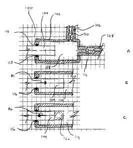
[0065] Figures 16A-16B are cross-sectional views of a dual chamber pump engine
1600,
according to an embodiment described and illustrated herein. Dual chamber pump
engine
23
, . . ........ . . .... ... ... . . .. . .. . . . ....... . . . .... . . .. .
CA 02670856 2009-06-30
1600 comprises cylinder 1601, first housing 1602, second housing 1603, stepped
piston
1604, first inlet 1606, second inlet 1607, first outlet 1608, second outlet
1609, first inlet
check valve 1610, second inlet check valve 1611, first outlet check valve
1612, second
outlet check valve 1613, first pump chamber 1614, second pump chamber 1615,
first
openings 1616, first seals 1618, second openings 1620, and second seals 1622.
Inlet
channels 1606 and 1607 may be connected to a reservoir, while outlet channels
1608 and
1609 may be connected to an infusion set. Stepped piston 1604 includes stepped
regions in
both the first and second pump chambers, and a piston stop 1624 in its middle.
Piston stop
1624 limits the travel of stepped piston 1604 along its axis by interacting
with the end
surfaces of cylinder 1601. Fluid flows into pump chambers 1614 and 1615
through inlets
1606 and 1607 and inlet check valves 1610 and 1611, while fluid flows out of
pump
chambers 1614 and 1615 through outlets 1608 and 1609 and outlet check valves
1612 and
1613. Inlet check valves 1610 and 1611 only allow flow into pump chambers 1614
and
1615, while outlet check valves 1612 and 1613 only allow flow out of pump
chambers
1614 and 1615. Stepped piston 1604 is sealed around its perimeter as it passes
through
openings 1616 and 1620 by seals 1618 and 1622. Stepped piston 1604 can move
back and
forth along its axis (as illustrated by arrows A 161 and A 162), while
maintaining a
hermetic seal between piston 1604 and housings 1602 and 1603.
[0066] Cylinder 1601, housings 1602 and 1603, and stepped piston 1604 can be
fabricated
using a wide variety of materials, including, but not limited to, polymers,
pure metals,
metal alloys, ceramics, and silicon. Polymers include ABS, acrylic,
fluoroplastics,
polyamides, polyaryletherketones, PET, polycarbonate, polyethylene, PEEK,
polypropylene, polystyrene, polyurethane, polyvinyl chloride, and polystyrene.
Pure
metals include titanium, platinum, or copper, while metal alloys include steel
and nickel
titanium (Nitinol). Seals 1618 and 1622 are typically made out of a polymer,
such as
natural or synthetic rubber, but can also be made out of metal, ceramic, or
silicon. Inlet
and outlet check valves 1610, 1611, 1612 and 1613 can be fabricated using
polymers,
metals, ceramics, and/or silicon, and frequently include a polymer component
(such as a
synthetic rubber ball or plug), and a metal component (such as a spring).
[0067] During a pump cycle, stepped piston 1604 moves back and forth along its
axis. For
example, as stepped piston 1604 moves in the direction indicated by arrow
A161, it pushes
fluid from first pump chamber 1614, through first outlet 1608 and first outlet
check valve
24
CA 02670856 2009-06-30
1612, into an infusion set. At the same time, stepped piston 1604 draws fluid
from a
reservoir, through second inlet 1607 and second inlet check valve 1611, and
into second
pump chamber 1615. Stepped piston 1604 then moves in the direction indicated
by arrow
A 162, drawing fluid from a reservoir, through first inlet 1606 and first
inlet check valve
1610, into first pump chamber 1614. At the same time, it pushes fluid from
second pump
chamber 1615, through second outlet 1609 and second outlet check valve 1613,
and into
an infusion set.
[0068] Figure 16B illustrates a sensing mechanism for detecting maximum piston
stroke.
In this embodiment, stepped piston 1604 includes first conductive surface 1630
and
second conductive surface 1632. As stepped piston 1604 moves in the direction
indicated
by arrow A163, and reaches its maximum stroke, first conductive surface 1630
contacts
first circuit 1626. As first conductive surface 1630 contacts first circuit
1626, the circuit is
completed, thus sensing the maximum stroke of stepped piston 1604 in the
direction
indicated by arrow A 163. As stepped piston 1604 moves in the direction
indicated by
arrow A164, and reaches its maximum stroke, second conductive surface 1632
contacts
second circuit 1628. As second conductive surface 1632 contacts second circuit
1628, the
circuit is completed, thus sensing the maximum stroke of stepped piston 1604
in the
direction indicated by arrow A 164. The sensing mechanism can be used to
trigger
actuation of stepped piston 1604. For example, a linear motor (as described
previously)
can be attached to one end of stepped piston 1604, while a spring is attached
to the other
end. The linear motor can be activated to move stepped piston 1604 in the
direction
indicated by arrow A163. As soon as the maximum stroke is reached, first
circuit 1626 is
completed, and the linear motor is turned off. The spring (which was
compressed as
stepped piston 1604 moved in the direction indicated by arrow A 163)
decompresses,
pushing stepped piston 1604 in the direction indicated by arrow A 164. As soon
as the
stepped piston reaches its maximum stroke, second circuit 1628 is completed,
and the
linear motor is turned back on, repeating the cycle.
[0069] Figures 17A-17B are perspective and cross sectional views of a
hydrophobic check
valve 1700, according to an embodiment described and illustrated herein.
Hydrophobic
check valve 1700 can be used to vent air during the filling of a reservoir,
and to prevent air
from flowing into a reservoir when liquids are drawn from the reservoir.
Hydrophobic
check valve 1700 comprises hydrophobic membrane 1702, elastic membrane 1704,
and
CA 02670856 2009-06-30
valve block 1706. Hydrophobic membrane 1702 allows air to pass, but blocks
water and
aqueous solutions. Hydrophobic membranes can be made out of a variety of
materials,
including Nylon, fluoropolymers, and polypropylene. Elastic membrane 1704
includes
sealing portion 1708, ribs 1707, and openings 1709. Elastic membrane 1704 can
be made
out of a variety of materials, but is often made out of an elastomer. Ribs
1707 allow
sealing portion 1708 to stretch back and forth, as it seals and unseals
against sealing
surface 1714. Openings 1709 allow air to escape when hydrophobic check valve
1700
opens. Valve block 1706 includes inlet 1710, outlet 1711, sealing surface
1714, and
bumps 1718. Bumps 1718 provide a gap between hydrophobic membrane 1702 and
valve
block 1706, allowing air to flow through hydrophobic membrane 1702 and into
inlet 1710.
Sealing surface 1714 surrounds outlet 1711, and fonns a seal with sealing
portion 1708
when the valve is closed. When hydrophobic check valve 1700 is assembled,
elastic
membrane 1704 is hermetically sealed at its edges to valve block 1706. In
addition,
hydrophobic membrane 1702 is hermetically sealed at its edges to the other
side of valve
block 1706. The outer edge of valve block 1706 can be hermetically attached to
reservoir
1716, as shown in Figure 17B. Valve block 1706 is typically rigid, and can be
made out a
variety of materials, such as metal or plastic. Sealing portion 1708 is in
direct contact with
sealing surface 1714, and is stretched to provide sealing force against
sealing surface
1714. When pressure builds in reservoir 1716, sealing portion 1708 is pushed
up,
disengaging sealing portion 1708 from sealing surface 1714, and allowing air
to flow
through hydrophobic membrane 1702 and valve block 1706. Alternatively, when
pressure
decreases in reservoir 1716, sealing portion 1708 is pushed against sealing
surface 1714,
preventing air from flowing into reservoir 1716. As long as atmospheric
pressure is greater
than or equal to the pressure in reservoir 1716, sealing portion 1708 will
seal against
sealing surface 1714, and prevent air from flowing through hydrophobic check
valve 1700
into reservoir 1716. If the pressure in reservoir 1716 is greater than the sum
of
atmospheric pressure plus the elastic tension pulling sealing portion 1708
down, air will
flow from reservoir 1716 and through hydrophobic check valve 1700. Hydrophobic
check
valve 1700 is particularly useful when incorporated in the pump engines and
systems
described and illustrated herein. For example, hydrophobic check valve 1700
can be
attached to a reservoir, allowing air to escape when the reservoir is being
filled, but
26
CA 02670856 2009-06-30
preventing air from being drawn into the reservoir as fluid passes from the
reservoir to the
pump engine.
[0070] Figures 18A-18B are perspective and cross sectional views of a
hydrophobic check
valve 1800, according to an embodiment described and illustrated herein.
Hydrophobic
check valve 1800 can be used to vent air during the filling of a reservoir,
and to prevent air
from flowing into a reservoir when liquids are drawn from the reservoir.
Hydrophobic
check valve 1800 prevents direct contact, in the reservoir, between a
hydrophobic
membrane and the contents of the reservoir. This is particularly beneficial
when the
reservoir contains pharmaceutical solutions, such as insulin, since aggregates
can form
when pharmaceutical solutions are in direct contact with hydrophobic surfaces.
Hydrophobic check valve 1800 comprises hydrophobic membrane 1802, elastic
membrane
1804, valve block 1806, and top cover 1805. Hydrophobic membrane 1802 allows
air to
pass, but blocks water and aqueous solutions. Hydrophobic membranes can be
made out
of a variety of materials, including Nylon, fluoropolymers, and polypropylene.
Elastic
membrane 1804 includes sealing portion 1808, ribs 1807, and openings (not
shown).
Elastic membrane 1804 can be made out of a variety of materials, but is often
made out of
an elastomer. Ribs 1807 allow sealing portion 1808 to stretch back and forth,
as it seals
and unseals against sealing surface 1814. The openings (not shown) in elastic
membrane
1804 allow air and liquid to escape when hydrophobic check valve 1800 opens.
Top cover
1805 is typically made out of a rigid material, such as plastic or metal, and
includes outlet
1811 and bumps 1818. Bumps 1818 provide a gap between hydrophobic membrane
1802
and top cover 1805, allowing air to flow through hydrophobic membrane 1802 and
through outlet 1811.Valve block 1806 includes inlet 1810, and sealing surface
1814.
Sealing surface 1814 surrounds inlet 1810, and forms a seal with sealing
portion 1808
when the valve is closed. When hydrophobic check valve 1800 is assembled,
elastic
membrane 1804 is hermetically sealed at its edges to valve block 1806 and top
cover
1805. In addition, hydrophobic membrane 1802 is hermetically sealed at its
edges to the
inside surface of top cover 1805. The outer edge of valve block 1806 can be
hermetically
attached to reservoir 1816, as shown in Figures 18A and 18B. Valve block 1806
is
typically rigid, and can be made out a variety of materials, such as metal or
plastic.
Sealing portion 1808 is in direct contact with sealing surface 1814, and is
stretched to
provide sealing force against sealing surface 1814. When pressure builds in
reservoir
27
CA 02670856 2009-06-30
1816, sealing portion 1808 is pushed up, disengaging sealing portion 1808 from
sealing
surface 1814, and allowing air and liquid to flow through valve block 1806 and
elastic
membrane 1804, as illustrated by arrows A 181 and A 182. Alternatively, when
pressure
decreases in reservoir 1816, sealing portion 1808 is pushed against sealing
surface 1814,
preventing air from flowing into reservoir 1816. As long as atmospheric
pressure is greater
than or equal to the pressure in reservoir 1816, sealing portion 1808 will
seal against
sealing surface 1814, and prevent air from flowing through hydrophobic check
valve 1800
into reservoir 1816. If the pressure in reservoir 1816 is greater than the sum
of
atmospheric pressure plus the elastic tension pulling sealing portion 1808
down, air and
liquid will flow from reservoir 1816 through valve block 1806 and elastic
membrane
1804. Air will continue to pass through hydrophobic membrane 1802, but liquid
will not.
Hydrophobic check valve 1800 is particularly useful when incorporated in the
pump
engines and systems described and illustrated herein. For example, hydrophobic
check
valve 1800 can be attached to a reservoir, allowing air to escape when the
reservoir is
being filled, but preventing air from being drawn into the reservoir as fluid
passes from the
reservoir to the pump engine. Figure 18B illustrates a slightly different
version of
hydrophobic check valve 1800. In this version, hydrophobic membrane 1802 and
elastic
membrane 1804 are not concentric, but are offset. As illustrated in Figure
18B, valve
block 1806 is fastened to reservoir 1816, and inlet 1810 and elastic membrane
1804 are
aligned on one end of valve block 1806. Outlet 1811 and hydrophobic membrane
1802 are
aligned on the other end of valve block 1806. Other than the relative position
of their
components, the hydrophobic check valves 1800 of Figures 18A and 18B function
the
same.
[0071] Figures 19A-19B are perspective and cross sectional views of a
hydrophilic/hydrophobic check valve 1900, according to an embodiment described
and
illustrated herein. Hydrophilic/hydrophobic check valve 1900 can be used to
vent air
during the filling of a reservoir, and to prevent air from flowing into a
reservoir when
liquids are drawn from the reservoir. Hydrophilic/hydrophobic check valve 1900
prevents
direct contact, in the reservoir, between a hydrophobic membrane and the
contents of the
reservoir. This is particularly beneficial when the reservoir contains
pharmaceutical
solutions, such as insulin, since aggregates can form when pharmaceutical
solutions are in
direct contact with hydrophobic surfaces. Hydrophilic/hydrophobic check valve
1900
28
CA 02670856 2009-06-30
comprises hydrophilic membrane 1902, spacer 1904, hydrophobic membrane 1906,
and
valve block 1908. Hydrophobic membrane 1906 and hydrophilic membrane 1902 are
hermetically sealed around their perimeters to valve block 1908, while spacer
1904 is
positioned between and supports hydrophobic membrane 1906 and hydrophilic
membrane
1902. Valve block 1908 includes outlet 1912, and can be attached to reservoir
1914.
Spacer 1904 and valve block 1908 are typically made out of rigid materials,
such as plastic
or metal. Hydrophobic membrane 1906 and hydrophilic membrane 1902 can be made
using a variety of materials, as long as hydrophobic membrane 1906 repels
water and
hydrophilic membrane 1902 attracts water. As reservoir 1914 is filled, air
moves toward
and passes through hydrophilic membrane 1902. Eventually, all of the air
passes through
hydrophilic membrane 1902, and is followed by liquid. Liquid passes through
hydrophilic
membrane 1902, and fills the cavity between hydrophilic membrane 1902 and
hydrophobic membrane 1906, pushing air through hydrophobic membrane 1906.
Eventually, the cavity between hydrophilic membrane 1902 and hydrophobic
membrane
1906 completely fills with liquid, but the liquid does not pass through
hydrophobic
membrane 1906. It is essentially trapped in the cavity between hydrophilic
membrane
1902 and hydrophobic membrane 1906. Once hydrophilic membrane 1902 fills with
liquid, air will no longer pass, as indicated by bubbles B in Figure 19A. In
addition, as
liquid is pumped from reservoir 1914, air cannot pass into reservoir 1914
because it won't
pass through hydrophilic membrane 1902 once it is wet. Figure 19B illustrates
hydrophilic
membrane 1902, spacer 1904, hydrophobic membrane 1906, and valve block 1908,
before
they've been assembled and attached to a reservoir. Hydrophilic/hydrophobic
check valve
1900 is particularly useful when incorporated in the pump engines and systems
described
and illustrated herein. For example, hydrophilic/hydrophobic check valve 1900
can be
attached to a reservoir, allowing air to escape when the reservoir is being
filled, but
preventing air from being drawn into the reservoir as fluid passes from the
reservoir to the
pump engine.
[0072] Figures 20A-20B are perspective views of reservoirs 2000 and 2002,
according to
an embodiment described and illustrated herein. Reservoirs 2000 and 2002
eliminate
undesirable air pockets while filling, and are particularly useful when
incorporated in the
pump engines and systems described and illustrated herein. As illustrated in
Figure 20A,
reservoir 2000 comprises first inlet channel portion 2004, second inlet
channel portion
29
CA 02670856 2009-06-30
2006, hydrophobic vent 2008, reservoir chamber 2010, and reservoir piston
2012. First
channel portion 2004 transitions in cross section to second channel portion
2006 before
reaching hydrophobic vent 2008. Hydrophobic vent 2008 can be made using a
variety of
materials, such as hydrophobic membranes. Reservoir chamber 2010, first
channel portion
2004, and second channel portion 2006 are typically made out of a rigid
material, such as
plastic or metal, while reservoir piston is typically made out of a semi-rigid
material such
as an elastomer or other plastic. When filling reservoir 2000, liquid is
injected through
first channel portion 2004 and second channel portion 2006 (as indicated by
arrow A20 1),
and reaches hydrophobic vent 2008. Air passes through hydrophobic vent 2008,
and, as
pressure increases, reservoir piston 2012 moves down, enlarging reservoir
chamber 2010
and filling it with liquid. As illustrated in Figure 20B, reservoir 2002
comprises inlet
2014, hydrophobic vent 2016, burst slit 2018, and reservoir chamber 2020.
Hydrophobic
vent 2016 can be made using a variety of materials, such as hydrophobic porous
plugs or
discs. Reservoir chamber 2020 is typically made out of a thin flexible film,
such as
polyethylene, polyester, or vinyl, and includes a heat seal 2022 around its
edge. Inlet 2014
is typically made out of a rigid material, such as plastic or metal, and
includes burst slit
2018 that allows flow into reservoir chamber 2020 when it is opened. When
filling
reservoir 2002, liquid is injected through inlet 2014 (as indicated by arrow
A203), and
reaches hydrophobic vent 2016. Air passes through hydrophobic vent 2016, and,
as
pressure increases, burst slit 2018 opens, allowing reservoir chamber 2020 to
completely
fill with liquid.
[0073] Figures 21A-21B are cross sectional and perspective views of a
peristaltic fluid
counter 2100, according to an embodiment described and illustrated herein.
Peristaltic
fluid counter 2100 measures the volume of fluid that flows through it, and is
particularly
useful when incorporated into the pump engines and systems described and
illustrated
herein. Peristaltic fluid counter 2100 can be placed adjacent to a reservoir
and used to
measure the amount of liquid loaded into the reservoir, or it can placed
adjacent to the
inlet or outlet of a pump engine to monitor the flow of liquid into or out of
a pump engine.
The embodiment illustrated in Figures 21A-21B is particularly useful in
monitoring the
volume of liquid that enters a reservoir during the filling of the reservoir.
As illustrated in
Figure 21A, peristaltic fluid counter 2100 comprises rotor 2102, flexible tube
2104,
septum 2106, constraining feature 2108, and switch 2110. Rotor 2102 includes
wipers
CA 02670856 2009-06-30
2101, shaft 2120, and cam 2122. As rotor 2102 rotates about shaft 2120, cam
2122 imparts
periodic motion to lever 2114, making and breaking electrical contact with
plate 2112.
Rotor 2102 can be made out of a variety of materials, both rigid and not
rigid, including
plastics and metals. In some embodiments, rotor 2102 is made out of a
lubricious polymer,
such as Delrin or Teflon, to reduce friction between rotor 2102 and flexible
tube 2104.
Flexible tube 2104 includes inlet 2101 and outlet 2105, and is elastic. In the
embodiment
illustrated in Figure 21A, inlet 2101 is connected to a source of liquid, such
as a vial, and
outlet 2105 is connected to a reservoir. Flexible tube 2104 can be made out of
a variety of
materials, including elastomers and plasticized PVC. Septum 2106 is connected
to inlet
2101, and allows a source of liquid (such as a vial) to be connected to
peristaltic fluid
counter 2100. Septum 2106 is typically made out of an elastomer, and is self
sealing.
Constraining feature 2108 supports flexible tube 2104, allowing flexible tube
2104 to
expand and contract as fluid flows through it. Constraining feature 2108 is
typically made
out of a rigid material, such as plastic or metal. Switch 2110 determines when
lever 2114
makes and breaks electrical contact with plate 2112, as rotor 2102 rotates
about shaft 2120
when fluid flows through flexible tube 2104. As fluid flows through septum
2106, into
inlet 2103, and through outlet 2105 (as indicated by arrow A212), the fluid
causes rotor
2102 to rotate in the direction indicated by arrow A211. As rotor 2102
rotates, cam 2122
moves lever 2116 up and down (as indicated by arrow A213), making and breaking
electrical contact between lever 2116 and plate 2112. Electrical contact
between lever
2116 and plate 2112 can be monitored using switch 2110, and can be correlated
to
volumetric flow through flexible tube 2104. Although in this example
peristaltic fluid
counter 2100 has been connected to a reservoir, peristaltic fluid counter can
be used
wherever flow occurs in any of the pump engines and systems described
previously.
[0074] While the invention has been described in terms of particular
variations and
illustrative figures, those of ordinary skill in the art will recognize that
the invention is not
limited to the variations or figures described. In addition, where methods and
steps
described above indicate certain events occurring in certain order, those of
ordinary skill
in the art will recognize that the ordering of certain steps may be modified
and that such
modifications are in accordance with the variations of the invention.
Additionally, certain
of the steps may be performed concurrently in a parallel process when
possible, as well as
performed sequentially as described above. Therefore, to the extent there are
variations of
31
CA 02670856 2009-06-30
the invention, which are within the spirit of the disclosure or equivalent to
the inventions
found in the claims, it is the intent that this patent will cover those
variations as well.
32