Language selection

Search

Patent 2671684 Summary

Third-party information liability

Some of the information on this Web page has been provided by external sources. The Government of Canada is not responsible for the accuracy, reliability or currency of the information supplied by external sources. Users wishing to rely upon this information should consult directly with the source of the information. Content provided by external sources is not subject to official languages, privacy and accessibility requirements.

Claims and Abstract availability

Any discrepancies in the text and image of the Claims and Abstract are due to differing posting times. Text of the Claims and Abstract are posted:

  • At the time the application is open to public inspection;
  • At the time of issue of the patent (grant).
(12) Patent: (11) CA 2671684
(54) English Title: PEENING APPARATUS AND METHOD
(54) French Title: APPAREIL A MARTELER ROTATIF ET METHODE
Status: Granted
Bibliographic Data
(51) International Patent Classification (IPC):
  • B24C 1/10 (2006.01)
(72) Inventors :
  • FORGUES, SYLVAIN (Canada)
  • LABELLE, BRIGITTE (Canada)
(73) Owners :
  • FORGUES, SYLVAIN (Canada)
  • LABELLE, BRIGITTE (Canada)
(71) Applicants :
  • FORGUES, SYLVAIN (Canada)
  • LABELLE, BRIGITTE (Canada)
(74) Agent: NORTON ROSE FULBRIGHT CANADA LLP/S.E.N.C.R.L., S.R.L.
(74) Associate agent:
(45) Issued: 2013-09-24
(22) Filed Date: 2009-07-13
(41) Open to Public Inspection: 2010-01-25
Examination requested: 2011-05-16
Availability of licence: N/A
(25) Language of filing: English

Patent Cooperation Treaty (PCT): No

(30) Application Priority Data:
Application No. Country/Territory Date
61/135,993 United States of America 2008-07-25

Abstracts

English Abstract

A method of peening a surface which comprises the steps of providing a rotary peening tool having at least one rotating flap mounted on the drive shaft which is rotatably driven, measuring the speed of the drive shaft, and controlling the speed of the drive shaft to maintain a desired level. A peening apparatus is also disclosed.


French Abstract

Une méthode de martèlement d'une surface qui comprend les étapes de fournir un outil à marteler rotatif ayant au moins un volet rotatif installé sur un arbre d'entraînement qui est entraîné par rotation, la mesure de la vitesse de l'arbre d'entraînement et le contrôle de la vitesse de l'arbre d'entraînement pour maintenir un niveau désiré. Un outil à marteler est également présenté.

Claims

Note: Claims are shown in the official language in which they were submitted.

CLAIMS:

1. The method of peening a surface comprising the steps of:
providing a rotary peening hand tool having at least one rotating flap
mounted on a drive shaft and having a drive means for imparting a drive force
for
rotatively driving said drive shaft;
controlling an adjustable means connected to said drive means to adjust
said drive force to maintain a substantially desired constant speed of
rotation of said drive
shaft;
rotating said rotary peening hand tool held in a hand of an operator person
to peen said surface;
monitoring the speed of said drive shaft by a sensor as it fluctuates due to
the pressure applied on said hand tool by the hand of said operator person;
feeding actual rotational speed signals of said drive shaft to a
microprocessor; and
controlling said adjustable means by said microprocessor to maintain said
substantially desired constant speed.
2. A rotary peening control apparatus for controlling the speed of a
rotary
peening hand tool when held in a hand of an operator person effecting a
peening operation,
comprising:
said rotary peening hand tool having a drive shaft and at least one rotating
flap mounted thereon, drive means for imparting a drive force for driving said
drive shaft;
an adjustable means connected to said drive means for adjusting said drive
force to maintain a substantially desired speed of rotation of said drive
shaft;
a sensor to monitor the speed of said drive shaft, said sensor feeding actual
rotational speed signals of said drive shaft to a microprocessor as the speed
of said drive
shaft fluctuates depending on pressure applied on said hand tool by the hand
of an operator
person;
said microprocessor operatively connected to said adjustable means to
increase or decrease the rotational speed to maintain said substantially
desired constant
speed.

- 6 -

3. The apparatus of claim 2 wherein said drive means comprise pneumatic
drive means, said adjustable means being an adjustable valve.
4. The apparatus of claim 3 wherein said rotary peening tool has a
plurality of
rotating flaps mounted on said drive shaft.
5. The apparatus of claim 2 wherein said microprocessor includes means for
storing operator parameters;
said operator parameters including monitored speed and intensity of said
peening hand tool used on a test piece material by a specific operator and
entered into said
microprocessor of said control apparatus to achieve a satisfactory peening
result, said
controller permitting operation of said peening hand tool by said specific
operator under
substantially identical conditions with said microprocessor controlling said
adjustable
means.
6. The method of claim I wherein there is further provided the steps of:
storing in said microprocessor operator parameters including monitored
speed and intensity of said peening hand tool used on a test piece of material
by a specific
operator;
entering said parameters into said microprocessor until a satisfactory
peening result is achieved by said specific operator, and wherein said step of
controlling said adjustable means is effected under substantially identical
conditions by said microprocessor to achieve said satisfactory peening result
when said
peening tool is operated again by said specific operator.
7. The method of claim 6 wherein said drive means is a pneumatic drive,
said
adjustable means is an adjustable valve connected to a pneumatic drive force
of said
pneumatic drive.

- 7 -

Description

Note: Descriptions are shown in the official language in which they were submitted.


CA 02671684 2009-07-13
PEENING APPARATUS AND METHOD
FIELD OF THE INVENTION
The present invention relates to a peening device and to a method for the
operation
thereof.
BACKGROUND OF THE INVENTION
As is known in the art, peening is the process of impacting a metal component
with
small particles generally at a right angle to the surface to be treated so as
to thereby impact
the surface of the metal in a direction normal thereto. The peening of the
metal surface
results in the material being stronger and tends to place the material in
compression and
relieve preexisting tensile stresses which may exist in the member. In other
words, the
impacting of the surface tends to place the same in compression and helps
prevent fatigue,
cracks and other imperfections in the surface from propagating through the
surface to cause
failure. The process in widely used in the aeronautical industry.
Conventional shot peening requires extensive blasting equipment and is not
particularly suited to situations which require mobility of the equipment.
Furthermore, in
many such situations, the particles are not easily collected for
recirculation. Rotary tools for
shot peening are known in the art and are more adapted for applications
requiring mobility.
The tool will comprise a rotating shaft having drive means associated
therewith and one or
more flaps are attached to the shaft. Each flap has one or more hard particles
or shot and the
flap impacts on the work piece. Each impact produces a localized compressive
stress on the
surface for the reasons set forth above.
Conventional rotating peening tools are generally light weight hand tools
which use a
plurality of peening flaps mounted on the shaft. Each flap has one or more
shot peening
- 1 -

CA 02671684 2009-07-13
particles affixed to its free end and the flap is driven to impact the work
surface as the flaps
rotate. The art shows many different arrangements for the shot on the rotating
flap.
As in any treatment, it is important to have proper control associated with
the rotary
peening treatment. In particular, the speed of rotation is critical in this
process. At the
present time, this is extremely difficult to provide since no speed controller
exists.
In particular, one operator may hold the tool closer to the work piece and
thus, the
peening flaps strike the member to be treated at a slower pace ¨ i.e. the
rotational speed is
decreased as the flap expends more energy to move past the work piece.
Inversely, if the
tool is held at a greater distance from the work piece whereby the outer
portions of the flaps
are utilized, the speed will be greater. Furthermore, the rotary peening
apparatus frequently
uses compressed air which often is provided through large compressors feeding
several
lines. When the demand on the compressor increases, the pressure in the lines
might drop
affecting the speed of the rotary peening apparatus.
Both the operator stability and the compressed air pressure variation, as well
as
several other factors, will have an impact on the speed of the rotary peening
apparatus. This
will have an influence on the energy transferred to the material and must
therefore be kept
as constant as possible to ensure a quality peening process.
SUMMARY OF THE INVENTION
It is an object of the present invention to provide a rotary peening speed
control
apparatus to control the rotational speed of the drive shaft and ensure proper
treatment of
the member being treated.
It is a further object of the present invention to provide a method for rotary
peening
that continuously monitors and controls the speed of rotation to ensure that
the operator
properly treats the member to be treated.
- 2 -

CA 02671684 2009-07-13
According to one aspect of the present invention, there is provided a method
of
peening a surface comprising the steps of providing a rotary peening tool
having at least one
rotating flap mounted on a drive shaft and having atrive means for rotatively
driving the
drive shaft, operating the rotary peening tool to peen the surface, measuring
the speed of the
drive shaft, and controlling the drive means to maintain a desired speed.
According to a further aspect of the present invention, there is provided a
peening
control apparatus comprising a rotary peening tool having a drive shaft and at
least one
rotating flap mounted thereon, drive means for driving the drive shaft, a
sensor to monitor
the speed of the drive shaft, a controller to receive input from the sensor,
the controller
being operatively connected to the drive means to increase or decrease the
rotational speed
to a desired value.
The apparatus of the present invention may include any suitable peening tool,
many
of which are commercially available. The number of flaps and/or the number of
shots on
each flap are irrelevant to the practice of the present invention.
The drive means may include any suitable and thus could include hydraulic,
pneumatic and electric. It suffices to say that all such means are known in
the art and could
be practiced with the present invention.
The controller of the present invention is designed to receive a signal from
the sensor
measuring the speed of the shaft and to increase and/or decrease the speed in
response to the
measurement. Such devices are known in the art.
According to the present invention, there is provided a control device which
maintains the required operating speed of the rotary peening tool.
Maintaining the speed of the shaft is extremely important, particularly in
cases where
- 3 -

CA 02671684 2013-01-29
the peening has been conducted on devices such as aeronautical components.
According to a still further broad aspect of the present invention there is
provided a
method of peening a surface which comprises the steps of providing a rotary
peening hand
tool having at least one rotating flap mounted on a drive shaft and having a
drive means
for imparting a drive force for rotatively driving the drive shaft. An
adjustable means
which is connected to the drive means is controlled to adjust the drive force
to maintain a
substantially desired constant speed of rotation of the drive shaft. The
method further
comprises rotating the rotary peening hand tool held in a hand of an operator
person to
peen the surface and monitoring the speed of the drive shaft by a sensor as it
fluctuates due
to the pressure applied on the hand tool by the hand of the operator person.
Actual
rotational speed signals of the drive shaft are fed to a microprocessor which
controls the
adjustable means to maintain the substantially desired constant speed.
BRIEF DESCRIPTION OF THE DRAWINGS
Having thus generally described the invention, reference will be made to the
accompanying drawings illustrating an embodiment thereof, in which:
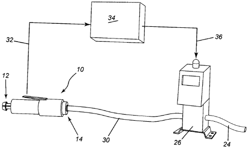
Figure 1 is a perspective view of a rotary peening tool;
Figure 2 is a perspective view illustrating the flaps which may be utilized
with the
rotary peening tool of Figure 1; and
Figure 3 is a schematic view illustrating the set up of the rotary peening
control
apparatus according to the present invention.
DETAILED DESCRIPTION OF THE INVENTION
Referring to the drawings in greater detail and by reference characters
thereto, there
is illustrated a typical rotary peening device generally designated by
reference numeral 10.
Such peening devices are well known in the art and have an arbour end 12 and
an air inlet
end 14. Arbour end 12 is designed to retain peening member 18. Each peening
member 18
comprises a shaft 20 and a pair of flaps 22. Naturally, any desired number of
peening flaps
22 may be provided and, as shown in Figure 2, different arrangements may be
utilized for
shaft 10.
Referring to Figure 3, an air supply line 24 feeds an adjustable valve 26. An
outlet
end of valve 26 has an air feed line 30 which is connected to air inlet 14 of
rotary peening
device 10.
- 4 -

CA 02671684 2011-05-16
The control apparatus includes a rotation speed sensor (not shown) which feeds
a
signal for the rotation speed sensor line 32 which is operatively connected to
a
microprocessor 34. Microprocessor 34 in turn sends a signal 36 to valve 26.
- 4a -
, ,

CA 02671684 2009-07-13
In operation, if the tool is being operated such that the speed of rotation is
not
sufficient, a signal is sent to valve 26 to increase the air pressure through
air feed line 30.
Inversely, if the speed of the arbour is too high, microprocessor 34 will send
a signal to
valve 26 to decrease the air pressure.
Naturally, other arrangements are possible. For example, if rotary peening
device 10
were electrically operated, the microprocessor 34 would be similar but the
corresponding
electric energy adjustor would be utilized to control the speed of rotation of
the arbour.
In one embodiment of the invention, the apparatus may be modified to include a

software which allows the input of operator parameters. Thus, the controller
would be
designed to accept individual operator parameters such as speed and intensity
of the
peening. For example, an operator would utilize the tool on a test piece of
material until a
satisfactory result is achieved. The parameters for that operator could then
be entered into
the controller to permit operation under substantially identical conditions. A
second
operator may achieve results with a different speed and the tool would be
operated at the
desired speed.
The controller could also have means to save the process data for quality
control
purposes. Similarly, an alarm could be included when the conditions are not
suitable.
It will be understood that the above described embodiments are for purposes of

illustration only and changes and modifications may be made thereto without
departing from
the spirit and scope of the invention.
- 5 -

Representative Drawing
A single figure which represents the drawing illustrating the invention.
Administrative Status

For a clearer understanding of the status of the application/patent presented on this page, the site Disclaimer , as well as the definitions for Patent , Administrative Status , Maintenance Fee  and Payment History  should be consulted.

Administrative Status

Title Date
Forecasted Issue Date 2013-09-24
(22) Filed 2009-07-13
(41) Open to Public Inspection 2010-01-25
Examination Requested 2011-05-16
(45) Issued 2013-09-24

Abandonment History

There is no abandonment history.

Maintenance Fee

Last Payment of $624.00 was received on 2024-06-14


 Upcoming maintenance fee amounts

Description Date Amount
Next Payment if standard fee 2025-07-14 $624.00 if received in 2024
$651.46 if received in 2025
Next Payment if small entity fee 2025-07-14 $253.00 if received in 2024
$264.13 if received in 2025

Note : If the full payment has not been received on or before the date indicated, a further fee may be required which may be one of the following

  • the reinstatement fee;
  • the late payment fee; or
  • additional fee to reverse deemed expiry.

Patent fees are adjusted on the 1st of January every year. The amounts above are the current amounts if received by December 31 of the current year.
Please refer to the CIPO Patent Fees web page to see all current fee amounts.

Payment History

Fee Type Anniversary Year Due Date Amount Paid Paid Date
Application Fee $200.00 2009-07-13
Request for Examination $800.00 2011-05-16
Maintenance Fee - Application - New Act 2 2011-07-13 $100.00 2011-06-14
Maintenance Fee - Application - New Act 3 2012-07-13 $100.00 2012-04-27
Final Fee $300.00 2013-05-06
Maintenance Fee - Application - New Act 4 2013-07-15 $100.00 2013-07-12
Maintenance Fee - Patent - New Act 5 2014-07-14 $200.00 2014-07-04
Maintenance Fee - Patent - New Act 6 2015-07-13 $200.00 2015-05-01
Maintenance Fee - Patent - New Act 7 2016-07-13 $200.00 2016-06-16
Maintenance Fee - Patent - New Act 8 2017-07-13 $200.00 2017-04-25
Maintenance Fee - Patent - New Act 9 2018-07-13 $200.00 2018-07-11
Maintenance Fee - Patent - New Act 10 2019-07-15 $250.00 2019-04-24
Maintenance Fee - Patent - New Act 11 2020-07-13 $250.00 2020-06-23
Maintenance Fee - Patent - New Act 12 2021-07-13 $255.00 2021-04-16
Maintenance Fee - Patent - New Act 13 2022-07-13 $254.49 2022-04-21
Maintenance Fee - Patent - New Act 14 2023-07-13 $263.14 2023-05-17
Maintenance Fee - Patent - New Act 15 2024-07-15 $624.00 2024-06-14
Owners on Record

Note: Records showing the ownership history in alphabetical order.

Current Owners on Record
FORGUES, SYLVAIN
LABELLE, BRIGITTE
Past Owners on Record
None
Past Owners that do not appear in the "Owners on Record" listing will appear in other documentation within the application.
Documents

To view selected files, please enter reCAPTCHA code :


To view images, click a link in the Document Description column. To download the documents, select one or more checkboxes in the first column and then click the "Download Selected in PDF format (Zip Archive)" or the "Download Selected as Single PDF" button.

List of published and non-published patent-specific documents on the CPD .

If you have any difficulty accessing content, you can call the Client Service Centre at 1-866-997-1936 or send them an e-mail at CIPO Client Service Centre.


Document
Description 
Date
(yyyy-mm-dd) 
Number of pages   Size of Image (KB) 
Abstract 2009-07-13 1 10
Description 2009-07-13 5 224
Claims 2009-07-13 2 45
Drawings 2009-07-13 2 20
Representative Drawing 2010-01-04 1 6
Cover Page 2010-01-14 1 29
Description 2011-05-16 6 237
Claims 2011-05-16 2 74
Description 2013-01-29 6 241
Claims 2013-01-29 2 79
Cover Page 2013-08-28 1 30
Prosecution-Amendment 2011-05-16 10 364
Assignment 2009-07-13 3 85
Correspondence 2009-09-08 3 83
Assignment 2009-07-13 3 92
Correspondence 2011-05-13 3 80
Correspondence 2011-05-26 1 13
Correspondence 2011-05-26 1 17
Prosecution-Amendment 2012-12-17 2 43
Prosecution-Amendment 2013-01-29 5 201
Correspondence 2013-05-06 2 63