Note: Descriptions are shown in the official language in which they were submitted.
CA 02671823 2013-02-19
MODULAR POWER CONVERTERS USABLE ALONE OR IN A MULTIPHASE POWER
CONVERTER
FIELD OF THE INVENTION
[0001] The present invention generally relates to the field of electrical
power converters. In
particular, the present invention is directed to a modular power converter and
a multiphase power
converter system having a group of modular power converters.
BACKGROUND
[0002] Power converters, such as three-phase power converters, used to
convert an input current
or voltage to an output current or voltage typically include complex
construction that results in large,
unwieldy devices. Known multiphase power converters often include complex
circuitry designed in
accordance with a specified application.
[0003] It is known to break multiphase power converters into discrete
modules, one for each
phase of output current. Unfortunately, the known modularized designs proposed
suffer from one or
more drawbacks that limit their full potential. These drawbacks include (i)
conduction and radiation
of electromagnetic energy that causes electromagnetic interference with
adjacent power converter
modules and other electronic equipment, (ii) multiple power and control wiring
connections that can
be challenging to connect due to space constraints, expertise and other
factors, (iii) the need for
custom engineering services using PhD or other high skill-set engineering
talent to design and/or
source components used with the modules, such as filters and inductor
networks.
SUMMARY OF THE DISCLOSURE
[0004] In one implementation, a power converter module usable with a
control system is
provided. The power converter module includes a power converter for converting
an input into an
output having a single phase; a control interface connected to the power
converter and configured for
connection to the control system; a first filter for filtering out first
components from the output; a
second filter for filtering out second components from the output; and an
enclosure surrounding the
power converter, the control interface, the first filter and the second
filter.
[0005] In another implementation, a power converter module is provided. The
power converter
module includes a power converter for converting one of (a) an input into a
single phase output and
1
4183469 vl
CA 02671823 2013-02-19
(b) one phase of a multiphase input into an output; and a control interface
connected to the power
converter and configured for connection to a control system. The control
interface includes
nonvolatile memory for storing information regarding the history of operation
and other attributes of
the power converter module.
[0006] In still another implementation, a multiphase power converter system
for converting an
input to an output having a plurality of phases is provided. The system
includes a control system; a
plurality of power converter modules connected to the control system, one for
each of the plurality
of phases. Each of the plurality of power converter modules has: a power
converter for converting
an input into an output having one phase of a plurality of phases, a control
interface connected to the
power converter and the control system, a first filter for filtering out first
components from the
output current, a second filter for filtering out second components from the
output current, and an
enclosure surrounding the power converter, the control interface, the first
filter and the second filter.
[0007] In yet another implementation, a power converter is provided. The
power converter
includes circuitry for converting an input to an output having different
electrical characteristics; at
least one heat sink thermally coupled with the circuitry; and a connection
coupling the heat sink to a
ground, the connection including a resistance.
BRIEF DESCRIPTION OF THE DRAWINGS
[0008] For the purpose of illustrating the invention, the drawings show
aspects of one or more
embodiments of the invention. However, it should be understood that the
present invention is not
limited to the precise arrangements and instrumentalities shown in the
drawings, wherein:
FIG. 1 is a schematic diagram of a multiphase power converter system having a
plurality of power
converter modules, each for converting an input to one phase of a multiphase
output;
FIG. 2A is a schematic diagram of one implementation of a power converter
module of the type used
in the multiphase power converter system of FIG. 1;
FIG. 2B is a schematic diagram of an alternative implementation of a power
converter module of the
type used in the multiphase power converter of FIG. 1;
FIG. 3 is a schematic diagram of a power converter module similar to the one
shown in FIG. 2A,
except that the circuitry used in the DC bus and switching network is
illustrated;
2
4183469 91
CA 02671823 2013-02-19
FIG. 4 is a schematic diagram of another power converter module similar to the
one shown in FIG.
2A, except that the circuitry used in the DC bus and switching network is
illustrated;
FIG. 5 is a schematic diagram of a switching network for use in a power
converter module, such as
the power modules of FIGS. 2A, 2B, 3, and 4; and
FIG. 6 is a schematic diagram of a slide assembly, electrical connectors and
other structure that may
be used to support a power converter module and permit ready connection and
disconnection from
input and output current/voltage and to a control system.
DETAILED DESCRIPTION
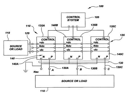
[0009] Referring now to the drawings, FIG. 1 illustrates a power conversion
system 100 that
includes a control system 105 in communication with a multiphase power
converter 110.
"Multiphase," as this term is used in connection with multiphase power
converter 110, refers to the
top-level phases in output current or voltage, e.g., the three phases in a
traditional three-phase power
system, and not subphases (sometimes also referred to as staggered phases or
interleaved phases)
within a given phase. Multiphase power converter 110 is connected between a
load or source 115
that receives or provides a single phase input on line 125 and a load or
source 116 that receives or
provides a multiphase output on line 130. As discussed more below, power
converter modules 135
are bidirectional, and so their direction of operation will influence whether
elements 115 and 116 are
sources or loads. For convenience of discussion, and without limiting the
manner in which power
converter modules 135 operate, the current and voltage carried on line 125 is
generally referred to as
an input and the current and voltage carried on line 130 will generally be
referred to as an output. In
all cases, the voltage of the phase output on line 130 will fall between the
positive and negative
voltage inputs on line 125.
[00101 Multiphase power converter 110 includes a plurality of power
converter modules 135,
e.g., modules 135A-C, which may be used alone or in the multiphase power
converter, as discussed
more below. While power converter modules 135 may be of any size, they
typically have greater
applicability when larger than lkW. Each power converter module 135 includes
module circuitry
140, e.g., module circuitry 140A-C, that generates either one phase of a
multiphase output or a single
phase output. For example, as illustrated in FIG. 1, power converter modules
135 A-C each provide
an output that constitutes one phase of a three-phase output. Although
multiphase power converter
3
4183469 vl
CA 02671823 2013-02-19
110 is illustrated in FIG. 1 with three power converter modules 135A-C (i.e.,
one power converter
module for each phase of the output on line 130), it is contemplated that the
multiphase power
converter may have any number of power converter modules 135, one or more for
each phase of the
output, as desired. In some cases it will be desirable to connect two or more
power converter
modules 135 in parallel for a given phase of output. Further, and as discussed
in more detail in
connection with FIGS. 2A and 2B below, it is contemplated that module
circuitry 140 is designed in
a manner to permit the individual power converter modules 135 to operate alone
in power
conversion system 110 or with other power converter modules in a multiphase
power converter 110
in a number of different configurations. These configurations include, for
example, a bi-directional
three-phase inverter, a bi-directional three-phase rectifier, a bi-directional
buck converter, a bi-
direction boost converter, a single phase converter (e.g., a dc-dc converter),
and a multiphase power
converter, among others.
[0011] FIGS. 2A and 2B illustrate implementations of power converter
modules 200 and 202,
respectively, in accordance with concepts of the present invention for use
alone or in multiphase
power converter 110 (FIG. 1). In particular, power converter modules 200 and
202 illustrate in more
detail examples of components that may be included in power converter modules
135. As such,
modules 200 and 202 may be used in multiphase power converter 110 wherever
modules 135 are
illustrated. Because modules 200 and 202 are essentially identical, the
description provided below
for module 200 also applies for module 202, except for certain differences in
EMI filtering that are
discussed below, and so a separate description for module 202 is not provided.
[0012] Power converter modules 200 and 202 are configured to provide a
single phase output
205 in response to an input 215. As discussed above, the terms "output" and
"input" are used here
for convenience, as modules 200 and 202 are bidirectional, and so the current
or voltage at 205 may
be an input and the current or voltage at 215 may be an output.
[0013] Power converter module 200 includes an enclosure 220 that surrounds
the various
components and internal circuitry of the power converter module discussed
below. In general,
enclosure 220 is constructed in a manner that blocks radiation of the various
forms of interference,
e.g., ripple current frequencies (typically lkHz to 100kHz) and EMI
frequencies (typically higher
than ripple current frequencies), generated by such components and circuitry
within the confines of
the enclosure. Various materials, such as, for example, steel and aluminum,
may be used in the
4
4183469v1
CA 02671823 2013-02-19
construction of enclosure 220 to provide sufficient interference protection
and also provide a
sufficiently ruggedized enclosure to safely support the contents thereof in
the intended operating
environments.
[0014] Power converter module 200 includes input nodes 225A-C that receive
input 215 and
output nodes 230A and 230B through which single phase output 205 may be
transmitted to a load
(not shown). When input 215 is a DC current or voltage, input nodes 225A-C may
function as a
positive node 225A, a negative node 225B and a neutral node 225C. In certain
cases it may be
desirable to omit or not make a connection with node 225B. Output node 230A
will function as a
neutral node and output node 230B will function as a phase node. In many
cases, it will be desirable
to locate input nodes 225A-C and output nodes 230A and B within enclosure 220
to contain
interference. The added benefits that result from the placement of the nodes
within enclosure 220 as
illustrated in FIG. 2A (and FIGS. 2B, 3, and 4) will be discussed more below.
[0015] Power module 200 also includes a ripple filter 235 and an EMI filter
240 that are
connected to filter the output provided at nodes 230A and B before reaching
the nodes. In one
implementation, as shown in FIG. 2A, ripple filter 235 is designed and
connected to filter out first
components from the output provided to nodes 230A and 230B. Typically, these
components are
frequencies in the range lkHz to 100kHz. Ripple filter 235 generally includes
a capacitor in parallel
with other circuit elements, e.g., inductors, other capacitors and resistors.
Similarly, EMI filter 240
is designed and connected to filter out second components from the output
provided to nodes 230A
and 230B, generally radio frequencies. These second components typically have
a higher frequency
than the first components filtered by ripple filter 235, although some overlap
may exist. In its
simplest form, EMI filter 240 is a capacitor, and in other implementations,
resistances and other
capacitors may be added. In power converter module 200 illustrated in FIG. 2A,
EMI filter 240 is
connected between neutral node 225C and neutral node 230A.
[0016] Other implementations of power module 200 in accordance with
concepts of the present
disclosure will feature other connection schemes for EMI filter 240. In power
converter module 202
illustrated in FIG. 2B, EMI filter 240 is implemented with a two-part
configuration, i.e., EMI filter
240A and 240B. EMI filter 240A is connected between node 225B and node 230A
and EMI filter
240B is connected between node 225A and node 230B. In any event, it is
desirable to attach EMI
filter 240 to ground, either directly or through other EMI filters. With the
exception of this
4183469 vl
CA 02671823 2013-02-19
difference in EMI filter 240, power converter modules 200 and 202 are
identical. Thus, the
following discussion of features in module 200 pertain also to module 202.
[0017] Connections in known power converters for the input and the output
are often positioned
outside of the enclosure of the power converters. As mentioned above and
illustrated in FIGS. 2A
and 2B, in power converter modules 200 and 202 it will often be desirable to
position these
connection points, i.e., input nodes 225A-C and output nodes 230A and B,
inside of enclosure 220 in
a manner that minimizes the conduction and radiation from the enclosure of
high-frequency
components emitted by these nodes. Such design enhancements will reduce
electromagnetic
interference with adjacent ones of power converter modules 200 or 202 present
in a multiphase
power converter 110 including power converter modules 200 or 202, or with
other adjacent
electronic devices. In this regard, conducted EMI radiation at any of nodes
225A-C and 230A-B
will typically be well below ldBV above 150kHz and below ldBmV above 20MHz.
[0018] Power converter module 200 further includes a power converter 245
that converts input
215 into an output having modified electrical characteristics, e.g.,
characteristics consistent with a
single phase AC output 205. More particularly, as discussed in connection with
FIG. 1 above,
power converter module 200 may be used to convert a variety of inputs into a
variety of outputs, as
desired. One implementation of power converter 245 includes a DC bus 255 and a
switching
network 260 that convert input 215 into an output current and voltage having
different form, e.g., a
single phase AC output making up one phase of a multiphase AC output or a DC
output of a
different form than input 215. DC bus 255 is connected to input nodes 225A-C
to receive input 215
and distribute it to switching network 260. Switching network 260 includes an
internal switching
circuitry, described in more detail in connection with FIGS. 3, 4 and 5 below,
that is configured to
generate a converted output.
[0019] The output from switching network 260 is provided to series
impedance network 265.
The latter includes one or more inductors (not shown in FIGS. 2A and 28) that
serve as part of ripple
filter 235 and EMI filter 240 and limit current ripple in these filters. The
output from series
impedance network 265 is provided to node 230B and ripple filter 235.
[0020] As indicated in FIG. 2A, ripple filter 235, EMI filter 240 and
series impedance network
265 are for most applications, although not necessarily, positioned inside
enclosure 220. This is in
6
4183469 vl
CA 02671823 2013-02-19
contrast to known modular power converters in which essentially just the
elements of power
converter 245 are positioned inside an enclosure. Accordingly, known modular
power converters
and associated inductors, filters and other components, as an entire assembly,
generate substantial
conducted and radiated electromagnetic energy. Developing the associated
filtering necessary to
control EMI in known modular power converters to appropriate levels typically
requires custom
engineering services, which precludes the use of "plug and play" functionality
as is achieved with
the power converter modules of the present disclosure.
[0021] In view of the foregoing, it is contemplated that a power converter
module 200 in
accordance with concepts of the present invention may also include internal
circuitry in accordance
with concepts discussed in U.S. Patent Application 11/850,103 ("the '103
Application"). The '103
Application discloses, among other things, several exemplary configurations of
power converters
that may be used in power converter module 200. In this connection, FIGS. 1-4
illustrate,
respectively, a buck converter circuit, a boost converter circuit, a half-
bridge circuit, and an
alternative buck converter circuit that are configured in a manner in which
they can be incorporated
into certain implementations of a power converter module 200 for use alone or
in multiphase power
converter 100 (FIG. 1). Further, converter cells of the type illustrated in
FIGS. 5A, 6A, 7A, 8, 9A,
10A and described in associated text in the specification of the '103
application, including associated
timing diagrams, may be used in whole or in part in certain implementations of
power converter 200.
[0022] Referring again to FIGS. 2A and 2B, power converter module 200 also
includes a
control interface 270 that is involved in controlling and protecting the
operation of the module. In
some implementations, control interface 270 also provides control information
to separate control
system 105 which is used by such control system in controlling the operation
of the power converter
module 200. In other implementations, power converter module 200 is controlled
by control
interface 270 alone. Control interface 270 is connected to sense input voltage
received at nodes
225A and 225B and to sense output current and voltage from series impedance
network 265. This
current and voltage information received by control interface 270 is used in
connection with
controlling the operation of power converter module 200 and may be provided as
control
information to control system 105, when used in power conversion network 100.
Power converter
module 200 may include various sensors (not shown) for monitoring the
operating state (e.g.,
temperature) and condition of various elements of the module, with the output
of such sensors being
provided to control interface 270 for use in controlling the operation of the
power converter module.
7
4183469 vl
CA 02671823 2013-02-19
More particularly, the output from various sensors in power converter module
200 may be used by
control interface 270 in connection with instantaneous current, voltage and
temperature shut-down
and latching. In this regard, problems in the software of control system 105
that could result in
power converter module 200 operating in a manner that could harm the module
will be addressed by
the shut-down and latching protection afforded by control interface 270.
[0023] In an alternative implementation of power converter module 200,
control interface 270
optionally includes a memory 290 that permits storage of information with
respect to the design and
operational history of power converter module 200. Memory 290, for instance,
may be a non-
volatile memory or other stable storage device (e.g., a memory card, floppy
drive, flash memory) in
communication with other aspects of control interface 270. It is contemplated,
for example, that
memory 290 may include a counter for operation hours, maintenance history and
identification
information, e.g., serial number. By providing identifying information
specific to the individual
power converter module 200, other power modules having similar functionality
can be easily
substituted without the need for detailed power engineering design and
analysis services.
[0024] Discussing in more detail the interrelationship between control
system 105 and control
interface 270, the control system provides signal processing control for power
conversion system
100. This signal processing control includes switch pattern generation,
current regulation and
voltage regulation. This control is accomplished using information sensed in
power converter
module 200 and provided to control system 105 via control interface 270.
Control system 105 also
functions as a communications interface with the "outside world" through
standard communication
protocols, e.g., Ethernet or RS 232, or, if desired, proprietary communication
protocols.
[0025] FIG. 3 illustrates a power converter module 300 in accordance with
concepts of the
present invention for use alone or in multiphase power converter 110. Power
converter module 300
is similar to power module 200, except that the details of one circuit
implementation of power
converter 245 are illustrated. Power converter module 300 includes an
enclosure 320 that surrounds
internal circuitry in a manner that permits the power module to limit
radiation of electromagnetic
energy, as discussed above with respect to other embodiments of the power
converter module.
Power converter module 300 further includes input nodes 325A-C, output nodes
330A and B, ripple
filter 335, EMI filter 340, power converter 345, an inductor 365, and control
interface 370, each of
which are similar to corresponding structures described above with respect to
other embodiments of
8
4183469 v1
CA 02671823 2013-02-19
the power converter modules. Power converter module 300 generates a single
phase output 305 in a
manner similar to that described in connection with FIGS. 2A and 2B, above.
[0026] More particularly, power converter 345 is connected to input nodes
325A-C, and
includes a power circuit 350 in the form of a half-bridge converter. Power
circuit 350 includes a
single power converter cell 360 and two series-connected DC bus capacitors 361
and 362. Power
converter cell 360 includes two series-connected power switches 367A-B. Power
switches 367A-B
are connected in parallel with DC bus capacitors 361, 362 and with snubber
capacitor 376. Devices
used for switches 367A-B may include IGBTs, MOSFETs, Bipolar transistors,
GT0s, MCTs, and
other power switches that can be turned on and off quickly and relatively
easily with minimal power
loss and reliability. In the implementation illustrated in FIG. 3, power
converter cell 360 includes a
pair of IGBT semiconductor devices that are used to generate a converted
single-phase output
provided on line 380 to inductor 365. For convenience of illustration, wiring
that carries control
information from interface circuit 370 to switches 367A-B is not illustrated.
[0027] FIG. 4 illustrates a power converter module 400 in accordance with
concepts of the
present invention that is structurally similar to power module 300 (FIG. 3),
described in detail above.
Here, power converter module 400 generates a single phase output 405 from
input 415. Like power
module 200, 300 discussed above, power module 400 includes an enclosure 420
that surrounds a
ripple filter 435, an EMI filter 440, a power converter 445, an interphase
transformer 455, an
inductor 465 and a control interface 470, all of which are configured to
generate single-phase output
405.
[0028] The internal circuitry of power converter 445 is different from the
internal circuitry of
power converter 345 (FIG. 3) described above. Here, power converter 445 is
connected to nodes
445A-C, and includes a power converter circuit 450 in the form of a three-cell
half-bridge converter.
Power converter circuit 450 includes three power converter cells 460A-C that
each include two
power switches 467A-B. Each power converter cell 460A-C generates a converted
output on lines
485A-C from input 415. In the present example, each converted signal on lines
485A-C is consistent
with a single phase of an AC signal. Unlike power converter 300 (FIG. 3) that
transmits a single
converted signal directly to the inductor, this power converter transmits
converted signals on lines
485A-C to interphase transformer 455. Generally, interphase transformer 455
(or, alternatively
known as an interphase reactor) and similar devices are known in the art as
being configured to
9
4183469 v1
CA 02671823 2013-02-19
generate a single phase of an output signal in response to multiple inputs.
Suitable designs for
interphase transformers 455 are described in the '103 application. Here,
interphase transformer 455
generates a transformed output on line 490 in response to converted input on
lines 485A-C.
Transformed signal on line 490, having a single phase of an AC signal, is
transmitted to the load (not
shown) via inductor 465.
[0029] FIG. 5 is a power semiconductor module 500 that can be used alone or
with a power
module in accordance with concepts of the present invention, such as power
modules 200, 300, 400.
Power semiconductor module 500 includes input nodes 505A-B and a power
converter circuit 510.
It is noted that power converter circuit 510 includes three power converter
cells 515A-C that each
include two power switches 520, the combination of which permits each power
converter cell 515A-
C to generate a converted signal on lines 535A-C.
[0030] Unlike the examples of the power converters above, power
semiconductor module 500
also includes a heat sink 540 in communication with a resistance 545 that is
connected to a ground
550. By contrast, it is believed that known power semiconductor heat sinks are
always connected
directly to ground without use of a resistance. The concept of connecting a
power semiconductor
heat sink to ground via a resistance is not limited to power semiconductor
modules of the type
described herein. This feature is more generally applicable to power
converters of any type.
[0031] Generally, it will be recognized by power electronics engineers that
the power converter
module 500 illustrated in FIG. 5 shows each switch 520A-C mounted to a single
heat sink. It is
contemplated, however, that each switch 520A-C can be mounted to a
corresponding individual heat
sink (not shown), or to other devices or in other configurations that
dissipate heat from the switch.
When multiple heat sinks 540 are utilized, each heat sink could include a
resistance to ground, or,
alternatively, all of the heat sinks may be in communication with a single
resistance to ground.
[0032] As discussed more below, a power converter module that includes a
heat sink connected
through a resistance to ground will improve EMI filter performance. It will be
recognized by those
skilled in the art, for instance, that the coupling capacitance between the
switches and the heat sink is
a source of common mode noise. For example, when the switches switch, the
large pulses of current
that flow through the coupling capacitance between the semiconductor switches
and the heat sink go
to ground, which cause fast current rise times in the system level ground.
Typically the noise caused
4183469 v1
CA 02671823 2013-02-19
by this current rise is filtered through various configurations of inductors
and shunted to ground by
capacitors found in the power converter or associated EMI filter.
[0033] It is contemplated that connecting the heat sink to ground through a
resistance lowers the
high frequency energy observed by the EMI filter by limiting the current in
these pulses and
spreading it over time. In one implementation, the resistance is equal to
about the characteristic
impedance of the parallel resonance between a series filter inductance and the
heat sink-to-substrate
capacitance of the switch assembly. In alternative implementations, the
resistance may vary in
accordance with:
R =.\1¨I' +/-50%. Equation 1
C
where R is the resistance, L is the parallel combination of series inductors,
and C is the total
capacitance of the circuit to the heat sink. In still other implementations
that include multiple heat
sinks, as mentioned above, L is the inductance associated with each
corresponding heat sink and C is
the capacitance associated with that corresponding heat sink.
[0034] Referring now to FIGS. 1 and 6, in addition to the various
electrical components of
power converter modules 135, 200, 202, 300, 400 and 500 that are designed and
configured to
support modularity, the power converter modules may also include mechanical
aspects that permit
quick and easy replacement of one power converter module with another.
Although the following
discussion of these mechanical aspects concerns power converter module 135 for
convenience, it is
to be appreciated that it applies equally to the other power modules
encompassed by the present
disclosure.
[0035] Power converter module 135 may be advantageously mounted on a slide
assembly 700
that permits the module to be easily installed and removed. Slide assembly 700
may include, for
example a pair of tracks 720 and power converter module 135 may include
associated rollers or
other structure (not shown) that co-acts with tracks 720 so as to allow power
converter module 135
to be moved back and forth along the tracks as indicated by arrow 730 relative
to bus 732. The latter
is connected to source or load 115 and source or load 116 and conducts input
and output current and
voltage to and from power converter module 135, when attached as described
below. In this regard,
bus 732 functions as both an electrical bus for carrying input and output
current and voltage and as a
11
4183469 vl
CA 02671823 2013-02-19
mechanical back plane for receiving power converter module 135, also as
described more below.
Bus 732 further includes electrical connectors 740 and 742. Electrical
connector 740 is connected to
source or load 115 and electrical connector 742 is connected to source or load
116. Electrical
connectors 740 and 742 are positioned in a predetermined position on bus 732,
as discussed more
below.
[0036] Power converter module 135 includes an enclosure 137 of the type
described above with
respect to other implementations of the power converter module, e.g.,
enclosure 220 of power
converter module 200. Power converter module 135 also includes electrical
connectors 750 and 752
which are generally, but not necessarily positioned inside enclosure 137.
Electrical connectors 750
and 752 are positioned on power converter module 135 so that when the module
is supported on
slide assembly 700 and moved toward bus 732, electrical connector 750 is
aligned with and may be
connected to electrical connector 740, and electrical connector 752 is aligned
with and may be
connected to electrical connector 742. Further, electrical connectors 740 and
750 and electrical
connectors 742 and 752 are designed to connect with one another so that when
power converter
module 135 is moved along slide assembly 700 electrical connection is
automatically achieved by
urging the connector pairs into engagement with one another. This "plug and
play" arrangement
facilitates quick connection of power converter module 135 to bus 732 and
ultimately to
current/voltage inputs and outputs from source/load 115 and source/load 116.
[0037] Power converter module 135 further includes another connector 754,
also in many, but
not necessarily all, cases positioned inside enclosure 137. This connector is
provided to allow quick
connection between control system 105 and power converter module 135, and is
accomplished with
electrical connector 756 that is connected by cable 758 to control system 105.
Quick release
connections (not shown) to sources of air and/or water may also be provided on
module 135.
[0038] The nature of the modular design of power converter modules 135,
200, 202, 300, 400
and 500 provides a number of benefits. These benefits include permitting the
power converter
modules to be quickly and easily installed and removed, minimizing conducted
and radiated
interference, e.g., electromagnetic interference (EMI) and ripple
interference, and minimizing the
extent of custom engineering services required in connection with use of the
modules, among others.
12
4183469 vl
CA 02671823 2013-02-19
100391
The scope of the claims should not be limited by the preferred embodiments set
forth
above, but should be given the broadest interpretation consistent with the
description as a whole.
13
4183469 v1